Homemade curtain drive
In this article I will talk about the design of an automatic drive curtains installed in my balcony. There we grow flowers that are harmful direct sunlight. In addition, in summer, if the balcony windows are closed, the air on the balcony quickly overheats in direct sunlight. However, when there is no direct light, it is advisable to open the curtains - the shadow also does not contribute to the growth of colors. Therefore, to maintain acceptable illumination on the balcony, I automated the operation of the curtains.
Mechanics
The curtains were originally on the balcony. There are two of them, both of them are suspended on a metal cable, stretched under the ceiling from one wall of the balcony to the other. It is clear that both curtains need to be moved at once, and due to the friction of the curtains on the cable (it is rather rough), the required force must be large enough. In addition, sometimes on the way the curtains can meet obstacles, for example, a slightly open balcony window, which further increases the requirements for strength.
Thus, the drive must be sufficiently powerful and reliable - there is often increased humidity on the balcony, a sufficiently large temperature difference is possible in winter and summer. Therefore, the basis of the drive, I made an automobile window drive. It has enough power, is capable of delivering large torque (a worm gear is built into it) and is very reliable.
Diagram of the mechanical part of the drive is shown below:

Read more about the design. A plastic roller with a groove, on which a coil of rope is wound, is fixed on the window lifter drive shaft (on the left in the diagram). The drive is fixed on one of the walls of the balcony. On the opposite wall is mounted the same roller, through which the rope is also forwarded.
After that, the rope is stretched, so that the friction of the rope on the drive roller is enough to move the curtains. The opposite ends of each curtain are attached to the rope so that when the motor rotates, the curtain moves apart or moves.
')
To test the drive, I made it a reduced model. A power window drive and an independent roller secured on the board, pulled a rope between them, after which it was possible to check the operation of the electronics and measure the force developed by the drive.
Photo of the drive itself on the layout:
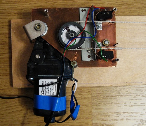
As can be seen from the photo, a fairly large thin plate is attached to the power window drive (I used textolite). A metal corner is fastened to it with two holes through which the rope is passed. It is needed so that the coil of the rope on the roller is not confused, for this hole in the corner made at different heights relative to the plate.
To the right of the corner are the limit switches needed to stop the curtains to their extreme positions. In order to mark these positions, two plastic tubes are put on the rope (only one of them is visible in the photo next to the bottom switch). The tubes are arranged so that when the curtain reaches the extreme position, one of them presses the switch, while for reliable pressing a metal plate is attached next to each of the switches, which presses the tube to the switch.
Three metal racks attached to the plate are needed to fix the drive cover.
Both roll rollers are made from furniture wheels. Using a drill and a file, in each of them you need to groove a groove, two turns of the rope should be laid in the groove of the drive roller. The drive roller is mounted on the shaft due to the tension, and the hole in it had to be squandered to a square one, since the drive shaft is square.
The drive is attached to the wall of the balcony with the help of suitable furniture corners (one of them is visible in the photo on the left). There are enough mounting holes in the power window drive, so there are no problems with mounting.
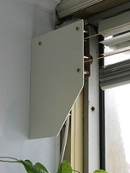
Type of drive already attached to the wall and covered with a lid:
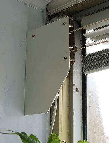
To tighten the rope, use a special screw with a nut, to which the ends of the rope are attached:

Also attached to it is the end of one of the curtains.
Electronics
All my electronics is divided into two parts - power and control. The main task of the power unit is to provide power to the drive motor. The power window drive can consume very high current. To reduce this current, I reduced the drive supply voltage to 5 volts, but even so, the maximum current consumed by the motor can go up to 3A. To provide such a current, I used a printer power supply capable of delivering a voltage of about 30V and a current of up to 0.7A, as well as a DC-DC converter of up to 5V. By lowering the voltage DC-DC is quite capable of delivering the desired current.
The motor power is controlled by a powerful relay designed to change the polarity of the signal, and a MOSFET that controls the voltage supply to the motor. Through the use of MOSFET, you can adjust the rotational speed of the engine, but at the moment this feature is not used.
Also on the power section are installed stabilizers designed to power the control electronics and the engine power control circuit. The stabilizers are powered by a lower voltage power supply circuit, the voltage there does not exceed 12V.
Power circuit diagram
The control electronics is represented by the STM8S microcontroller. The controller performs quite a lot of functions - measuring the light, making decisions about starting the drive, controlling the position of the curtains by the limit switch, driving power control, driving the drive in manual mode - by remote control commands. In addition, a radio module on the NRF24L01 and a 1-Wire bus, through which three temperature sensors are connected, are connected to the controller. Using the radio module, you can control the drive and read the temperature values at different points of the balcony and outside, but at the moment the second radio module is connected only to the prototype board, so I will not consider this functionality further.
The used power supply unit from the printer has an input for transferring it to the Stand-by state. I also use it, which reduces the energy consumption of the structure. The program takes into account that the power supply goes into working mode with a certain delay, and after 30 seconds of inactivity of the drive, the power supply goes back to Stand-by mode.
Indication of the drive operation - using a three-color LED (only blue and red diodes are used). Blue lights up when voltage is applied to the motor, red starts flashing periodically in the presence of errors in the drive. The number of flashes allows you to determine the error number.
To sound some events (for example, when giving the command to close curtains already closed), the drive motor itself is used. It receives a PWM signal with a small fill factor, as a result of which the engine beeps loudly enough.
Control part scheme
A photoresistor attached by a suction cup to the window is used as the light sensor. Since the suction cup may fall off the window, there is a small button next to the photoresistor. While the suction cup is holding onto the window, the button is pressed against the window. If the sucker disappears, the drive automatically stops and the red diode starts flashing. If the sensor is not connected to the connector, this is also detected by the controller.
View of the light sensor:

Since the sensor illumination can change dramatically - due to various outbreaks on the street, variable cloudiness, the data from the sensor must be filtered. I have implemented the following processing algorithm: data from the sensor is digitized at a frequency of 10 Hz, and recorded in an array. Every second, the value of this array is averaged (first of all, it is necessary for filtering noises and flashes). Next, the resulting values are added to another array of 600 elements, after reaching the end of the array, the recording begins from the beginning. Also, this array is analyzed every second - the controller calculates what percentage of array elements is less than a certain threshold (as the illumination increases, the voltage at the photosensor output drops). If the values of more than 66% of the elements are less than the specified threshold, then it is considered that the illumination is large enough and the curtains can be closed. Thus filtering of periodic changes in illumination. In this case, the frequency of the drive is also limited - in automatic mode, the motor is switched on no more than once every ten minutes.
As I mentioned above, it is possible to control the curtains with the remote control. With the help of the remote, you can fully open and close the curtains, partially open them, start the drive according to the instantaneous light value. When operating from the console, there are no restrictions on the frequency of the drive.
It is also possible to programmatically restart the controller.
When moving the curtains, the controller monitors the state of the limit switches. If after the start of movement the corresponding switch does not work within 20 seconds, the motor stops working. To continue the drive after troubleshooting, just need to restart the controller.
All electronics are installed in a standard plastic case:
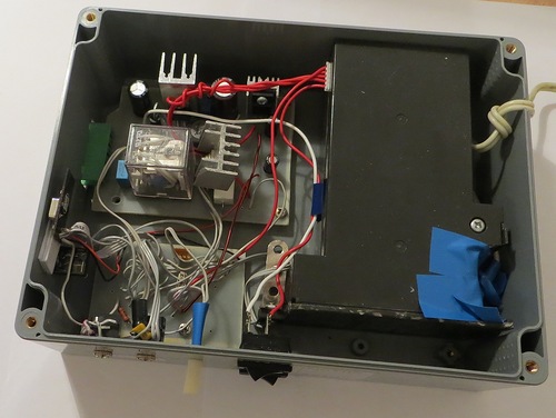
One of the switches is needed to switch the electronics into automatic mode, the second allows you to completely turn off the power to the motor.
Using the 3.5mm jack jacks, a light sensor, a TSOP for receiving data from the console, and external thermal sensors are connected to the device.
The white cap is closed LED - so it can be seen from any angle.
View assembled and installed in its place electronics unit:

Video of the drive (control from the console):
Source code of the controller program
Source: https://habr.com/ru/post/211893/
All Articles