Toothpick-detective reveals the secret of the radio protocol
This is a small sketch to the story about " Convenient Home ". Just an illustration of the fact that even with not too much knowledge and experience something can be achieved. In other words, a sufficiently persistent woodpecker zadolbit any tree.
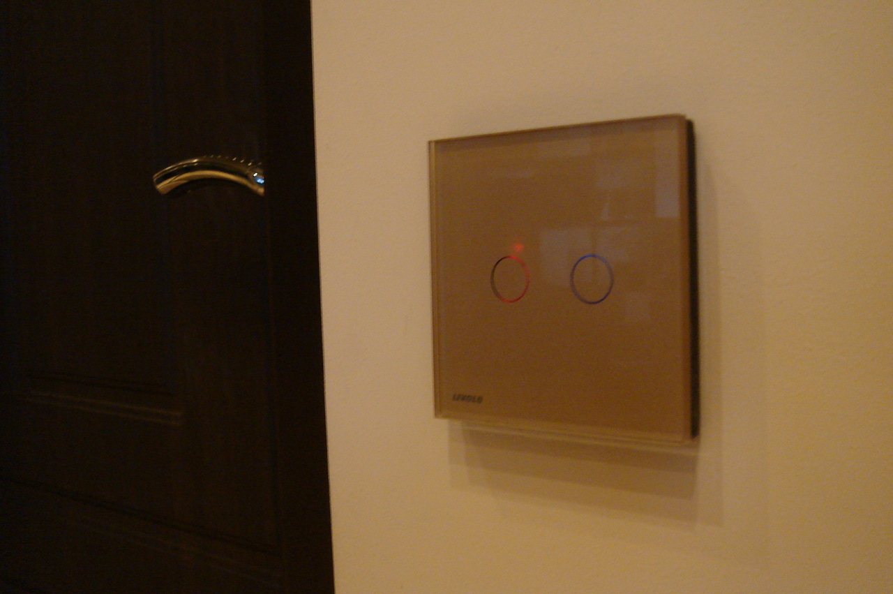
It all started with a simple desire to control the light in the house with the help of Arduino. Including - switches Livolo , bought before this crazy undertaking with home automation. But, unlike radio sockets, “clicking” them with the help of my favorite library RC-Switch did not work, and the search for other ready-made solutions showed their complete absence.
Yes, and the Chinese manufacturers, vendors to the question about the protocol answered that this thing works at a frequency of 433 MHz. Not too useful information. However, I will not depict the holy innocence. After all, I, along with Arduino, bought a couple of blocks of four relays so that, if anything, it is trite to close the remote control buttons. And this, by the way, is quite a popular decision, because it is fast, relatively cheap and very angry.
')
But in my heart I strove for beauty. Strangely enough, the usual toothpick, two resistors and one capacitor helped.
At first, however, I did not think about toothpicks. But in the process of reading any more or less simple decoding of radio protocols, I came across a wonderful resource NetHome. And there, the author publishes, firstly, a divider circuit that allows you to record a demodulated signal from the receiver to a computer via a normal microphone input and at the same time - a simple Protocol Analyzer utility for recording and analyzing the signal.
. heroes of the day

So I assembled the divider, connected it to the laptop, pressed the remote control button, and looked at the results - fortunately, the (amplitude) modulation of the console coincided with the modulation of the receiver. Protocol Analyzer is generally a pretty cool thing. The program identifies the most popular protocols, and if it encounters the unknown, you can see an “oscillogram” with a layout by impulses. Unfortunately, she did not know the Livolo protocol. And even confused me a little, since it did not quite clearly show the true form of the Livolo remote control signal.
It turned out by chance when it occurred to me to see the signal also in Audacity . Here the pulses became clearly visible and, as it seems to me, the reason for the troubles of the Protocol Analyzer is obvious: the extremely short duration of these pulses is from 100 to 500 microseconds. In the same editor, I decided to go a simple way - to record the received signal in WAV, and then reproduce it using the Arduino on the pin to which the transmitter is connected. After all, I also had an Ethernet-shield with a microSD slot, which was quite suitable for a “player”. With a bit of searching, the “music” library TMRpcm was also found .
. this is what protocol analyzer showed

. compare with Audacity

The idea was based on the fact that IR protocols similar in their essence are successfully and fairly simply simulated by connecting the IR LED to the computer’s audio output or other gadget capable of reproducing sound with suitable parameters. No sooner said than done. And put aside: the switches did not understand the joke, and a viewing of the signal emitted in this way in Audacity showed that the pulse shape was too distorted.
Then I decided on extreme measures. Namely - stupidly repeat the waveform, without going into a logical level. To do this, it is necessary and rather hard to encode the code parcels in the Arduino sketch. And here I am very lucky.
If we consider the code parcel of the Livolo console, we can see that it consists of a set (about 100) of multiple repetitive pulse packets. So, all the packets in the code message are exactly the same - this is a kind of protection from interference: an excessive number of packets ensures, firstly, reliable capture of the receiver's AGC signal, and, secondly, the reception of the command itself.
. Here's a picture, if you press the buttons in a row

. understand where the signal, and where the noise is quite simple. Here you can estimate the scale of the disaster: the signal is just one button.

But not only the impulse packets within the same code package turned out to be the same. Livolo also uses a system of fixed codes, that is, the same pulse packet always corresponds to a single button on the console. It is easy to verify this: you only need to press the same button several times and compare the results. In my case, they were all completely identical.
. repetition is not only the mother of learning, but also a guarantee of a confident signal reception

This is what I call luck: fixed code without any frills.
Thus, it was required to consistently press and record the signal of all the necessary buttons on the console in Audacity, and then calculate the number of pulses in the packet of each button, find out their duration and transfer it all to the Arduino code. This required a tool that is thin enough not to close the signal review in Audacity and neutral enough so as not to scratch the laptop display during the process.
And here came the high point of the toothpick. In fact, the art of counting impulses only through my eyes is not available to me, but if you use a pointer, nothing at all. In one hand - a toothpick, the other immediately recorded the results.
With sufficient magnification, it can be seen that the packet consists of five types of pulses (conditionally: long down, short up, short down, middle up, middle down).
.

If you increase it even further, you can estimate by eye the length of the pulses along the Audacity line, which I did for all five. In addition, each pulse has been assigned a sequence number — this is based on using byte variables to save Arduino memory. I just now thought that it would be possible to divide by 10 and not suffer with “abbreviations”.
. The theoretical limits of the pulses are highlighted in blue and red, since ideally the fronts should be vertical, but that is if there is no radio channel

The work was not so much intellectual as dreary. The number of individual pulses "floated" from button to button. And although I assumed that from a reasonable point of view it should not be so, I did not reach the logical level analysis. Just coded the result and tried it in work.
From the first, nothing happened. However, it was expected. What I did not expect was the fact that everything would work the second time. But the thing turned out to be that with direct encoding (i.e. if the pulse is up, we encode OUTPUT / HIGH) the signal turned out to be inverted - obviously, this is a feature of the transmitter. It was easy to solve this: we invert the levels in the code (i.e. the impulse upwards we encode OUTPUT / LOW). A comparison of the imitation and the original signal (in Audactiy, by eye) also showed a slight discrepancy in the length of the pulses - I also corrected it.
The final touch of this stage was the insertion of code sequences into the Arduino flash memory (PROGMEM), so as not to occupy precious operational data. In this form, the travel code, in my opinion, is more than half a year, and then I became bored, and in general I again wanted something beautiful.
Once again, looking at the WAV, I did not really hope for anything. However, more careful than before, the comparison of the code parcels gave a pleasant surprise. Part of the sequence at the beginning of each packet of pulses turned out to be common for all packets of one code parcel, and for all buttons on the console in general.
. cutting different buttons - and it’s immediately obvious that part of the package does not change

Understanding the protocol was still far away, but this small discovery made it possible to further save controller memory. I simply brought a single part of the package into a separate array, which was automatically “played back” before each unique part.
Despite some success and the fact that the code worked quite well and did not ask for bread, I continued to be vaguely disturbed by the fact that the number of pulses in the packages was different. On the one hand, nothing prevented the protocol from having such a feature, but on the other hand, there were many examples of similar protocols at hand (from sockets, for example, weather stations), where there was a tendency to a 24-bit message.
The third approach to the machine was that I tried to solve the logic of the protocol developer. From the very beginning it was more comfortable for me to assume that short impulses denote “0”, and of medium duration - “1”. At the same time, I took the longest impulse in the package as the starting one, and did not burden it with a different meaning.
It remained to figure out why impulses are combined up and down (for different durations this does not seem necessary), and how to understand this in general. The process ended with the following conclusions:
1. There is a clear rule of impulse following: the impulse "up" always goes the impulse "down", regardless of the duration of the impulse.
2. Two short pulses in a row in my coordinate system mean "0".
3. Similarly, each pulse of average duration means “1”.
4. The longest impulse of the parcel - start or stop, which does not matter and depends only on the point of view.
If we apply these rules to a pulse train, it becomes clear that its total length is always 24 bits, including the start-stop. Of these, 16 bits are the previously “fixed” part and 7 bits are the part unique for each digital button on the remote. Actually, the constant length of the packet led me to the conclusion that the identification of the logical level was successful.
. by all the rules

From the “format” of the package, it naturally followed that the 16-bit fragment is most likely an identifier of the console, allowing the use of several consoles in the same apartment, or not interfering with the neighbors if they have the same switches. Fortunately, I also had in my hands a recording of another remote control, from which it followed that the codes of the numeric buttons were the same for both remotes.
All together it means that there is a great opportunity to imitate an almost unlimited number of Livolo remotes, depending on your own fantasies and needs. The main thing is to follow the rule: 16 bits - the remote control ID, and use either known buttons, or generate them according to the 7-bit principle - the “button”.
Practice, however, has shown that not all 16-bit remote identifiers are suitable. But it is not too scary: according to the same practice, finding a suitable identifier is not difficult.
It remains only to rewrite the code, and finally get rid of these terrible clumsy arrays.
In principle, it would be possible to stop on the new code, but it still cluttered the main program, and others who would like to use it would have to resort to unnecessary copy-paste. So I decided to practice a little “on cats” and turn it into a separate library.
In this process, the instruction on the website Arduino.cc provided invaluable assistance. In Russian, the instruction is published on Arduino.ru .
It turned out exactly the recipe (no step to the side, no jumps on the spot). File h, cpp, readme and a small example showing how to use all this happiness.
Or all in one archive .
Actually, I managed to solve the main task - an imitation of an arbitrary Livolo console for controlling switches, but I could not “read” the identifier of an existing one. To do this, anyone who wants to imitate his console (to use it in parallel with the Arduino) would have to record his signal in Audacity (or something similar) and calculate the identifier by code message.
Not too nice, but I couldn’t do anything about it (that time was not enough, then I didn’t mind), and a little later the necessity disappeared. The code was written by one of the comrades who got acquainted with my sufferings about Livolo.
That's all. Report on the laboratory work finished.
It all started with a simple desire to control the light in the house with the help of Arduino. Including - switches Livolo , bought before this crazy undertaking with home automation. But, unlike radio sockets, “clicking” them with the help of my favorite library RC-Switch did not work, and the search for other ready-made solutions showed their complete absence.
Yes, and the Chinese manufacturers, vendors to the question about the protocol answered that this thing works at a frequency of 433 MHz. Not too useful information. However, I will not depict the holy innocence. After all, I, along with Arduino, bought a couple of blocks of four relays so that, if anything, it is trite to close the remote control buttons. And this, by the way, is quite a popular decision, because it is fast, relatively cheap and very angry.
')
But in my heart I strove for beauty. Strangely enough, the usual toothpick, two resistors and one capacitor helped.
Epic dips
At first, however, I did not think about toothpicks. But in the process of reading any more or less simple decoding of radio protocols, I came across a wonderful resource NetHome. And there, the author publishes, firstly, a divider circuit that allows you to record a demodulated signal from the receiver to a computer via a normal microphone input and at the same time - a simple Protocol Analyzer utility for recording and analyzing the signal.
. heroes of the day
So I assembled the divider, connected it to the laptop, pressed the remote control button, and looked at the results - fortunately, the (amplitude) modulation of the console coincided with the modulation of the receiver. Protocol Analyzer is generally a pretty cool thing. The program identifies the most popular protocols, and if it encounters the unknown, you can see an “oscillogram” with a layout by impulses. Unfortunately, she did not know the Livolo protocol. And even confused me a little, since it did not quite clearly show the true form of the Livolo remote control signal.
It turned out by chance when it occurred to me to see the signal also in Audacity . Here the pulses became clearly visible and, as it seems to me, the reason for the troubles of the Protocol Analyzer is obvious: the extremely short duration of these pulses is from 100 to 500 microseconds. In the same editor, I decided to go a simple way - to record the received signal in WAV, and then reproduce it using the Arduino on the pin to which the transmitter is connected. After all, I also had an Ethernet-shield with a microSD slot, which was quite suitable for a “player”. With a bit of searching, the “music” library TMRpcm was also found .
. this is what protocol analyzer showed
. compare with Audacity
The idea was based on the fact that IR protocols similar in their essence are successfully and fairly simply simulated by connecting the IR LED to the computer’s audio output or other gadget capable of reproducing sound with suitable parameters. No sooner said than done. And put aside: the switches did not understand the joke, and a viewing of the signal emitted in this way in Audacity showed that the pulse shape was too distorted.
Shape repetition
Then I decided on extreme measures. Namely - stupidly repeat the waveform, without going into a logical level. To do this, it is necessary and rather hard to encode the code parcels in the Arduino sketch. And here I am very lucky.
If we consider the code parcel of the Livolo console, we can see that it consists of a set (about 100) of multiple repetitive pulse packets. So, all the packets in the code message are exactly the same - this is a kind of protection from interference: an excessive number of packets ensures, firstly, reliable capture of the receiver's AGC signal, and, secondly, the reception of the command itself.
. Here's a picture, if you press the buttons in a row
. understand where the signal, and where the noise is quite simple. Here you can estimate the scale of the disaster: the signal is just one button.
But not only the impulse packets within the same code package turned out to be the same. Livolo also uses a system of fixed codes, that is, the same pulse packet always corresponds to a single button on the console. It is easy to verify this: you only need to press the same button several times and compare the results. In my case, they were all completely identical.
. repetition is not only the mother of learning, but also a guarantee of a confident signal reception
This is what I call luck: fixed code without any frills.
Thus, it was required to consistently press and record the signal of all the necessary buttons on the console in Audacity, and then calculate the number of pulses in the packet of each button, find out their duration and transfer it all to the Arduino code. This required a tool that is thin enough not to close the signal review in Audacity and neutral enough so as not to scratch the laptop display during the process.
And here came the high point of the toothpick. In fact, the art of counting impulses only through my eyes is not available to me, but if you use a pointer, nothing at all. In one hand - a toothpick, the other immediately recorded the results.
With sufficient magnification, it can be seen that the packet consists of five types of pulses (conditionally: long down, short up, short down, middle up, middle down).
.
If you increase it even further, you can estimate by eye the length of the pulses along the Audacity line, which I did for all five. In addition, each pulse has been assigned a sequence number — this is based on using byte variables to save Arduino memory. I just now thought that it would be possible to divide by 10 and not suffer with “abbreviations”.
. The theoretical limits of the pulses are highlighted in blue and red, since ideally the fronts should be vertical, but that is if there is no radio channel
The work was not so much intellectual as dreary. The number of individual pulses "floated" from button to button. And although I assumed that from a reasonable point of view it should not be so, I did not reach the logical level analysis. Just coded the result and tried it in work.
From the first, nothing happened. However, it was expected. What I did not expect was the fact that everything would work the second time. But the thing turned out to be that with direct encoding (i.e. if the pulse is up, we encode OUTPUT / HIGH) the signal turned out to be inverted - obviously, this is a feature of the transmitter. It was easy to solve this: we invert the levels in the code (i.e. the impulse upwards we encode OUTPUT / LOW). A comparison of the imitation and the original signal (in Audactiy, by eye) also showed a slight discrepancy in the length of the pulses - I also corrected it.
The first version, the great and terrible
int txPin = 9; // pin connected to RF transmitter int i; // counter to send command pulses int pulse; // count pulse repetitions int incomingByte = 0; // for incoming serial data // hard coded commands (see txButton): 1 - pulse start, 2 - zero, 3 - one, 4 - pause, 5 - low int button1[45]={44, 1, 2, 4, 2, 4, 2, 4, 3, 5, 2, 4, 2, 4, 3, 4, 2, 4, 2, 4, 2, 4, 2, 4, 2, 4, 2, 4, 2, 4, 2, 4, 2, 4, 2, 4, 2, 4, 2, 4, 2, 4, 2, 4, 2}; int button2[43]={43, 1, 2, 4, 2, 4, 2, 4, 3, 5, 2, 4, 2, 4, 3, 4, 2, 4, 2, 4, 2, 4, 2, 4, 2, 4, 2, 4, 2, 4, 2, 5, 3, 4, 2, 4, 2, 4, 2, 4, 2, 4, 2}; int button3[41]={40, 1, 2, 4, 2, 4, 2, 4, 3, 5, 2, 4, 2, 4, 3, 4, 2, 4, 2, 4, 2, 4, 2, 4, 2, 4, 2, 4, 2, 4, 2, 5, 3, 5, 3, 4, 2, 4, 2, 4, 2}; int button4[43]={42, 1, 2, 4, 2, 4, 2, 4, 3, 5, 2, 4, 2, 4, 3, 4, 2, 4, 2, 4, 2, 4, 2, 4, 2, 4, 2, 4, 2, 4, 2, 4, 2, 4, 2, 5, 3, 4, 2, 4, 2, 4, 2}; int button5[43]={42, 1, 2, 4, 2, 4, 2, 4, 3, 5, 2, 4, 2, 4, 3, 4, 2, 4, 2, 4, 2, 4, 2, 4, 2, 4, 2, 4, 2, 4, 2, 5, 2, 4, 3, 4, 2, 4, 2, 4, 2, 4, 2}; int button6[43]={42, 1, 2, 4, 2, 4, 2, 4, 3, 5, 2, 4, 2, 4, 3, 4, 2, 4, 2, 4, 2, 4, 2, 4, 2, 4, 2, 4, 2, 4, 2, 4, 2, 5, 3, 4, 2, 4, 2, 4, 2, 4, 2}; int button7[41]={40, 1, 2, 4, 2, 4, 2, 4, 3, 5, 2, 4, 2, 4, 3, 4, 2, 4, 2, 4, 2, 4, 2, 4, 2, 4, 2, 4, 2, 4, 2, 5, 3, 4, 2, 5, 3, 4, 2, 4, 2}; int button8[43]={42, 1, 2, 4, 2, 4, 2, 4, 3, 5, 2, 4, 2, 4, 3, 4, 2, 4, 2, 4, 2, 4, 2, 4, 2, 4, 2, 4, 2, 4, 2, 4, 2, 4, 2, 4, 2, 5, 3, 4, 2, 4, 2}; int button9[43]={42, 1, 2, 4, 2, 4, 2, 4, 3, 5, 2, 4, 2, 4, 3, 4, 2, 4, 2, 4, 2, 4, 2, 4, 2, 4, 2, 4, 2, 4, 2, 5, 2, 4, 2, 4, 3, 4, 2, 4, 2, 4, 2}; int button10[43]={42, 1, 2, 4, 2, 4, 2, 4, 3, 5, 2, 4, 2, 4, 3, 4, 2, 4, 2, 4, 2, 4, 2, 4, 2, 4, 2, 4, 2, 4, 2, 4, 2, 5, 2, 4, 3, 4, 2, 4, 2, 4, 2}; int button11[41]={40, 1, 2, 4, 2, 4, 2, 4, 3, 5, 2, 4, 2, 4, 3, 4, 2, 4, 2, 4, 2, 4, 2, 4, 2, 4, 2, 4, 2, 4, 2, 5, 3, 4, 2, 5, 2, 4, 3, 4, 2}; void setup () { pinMode(txPin, OUTPUT); Serial.begin(9600); Serial.println("Number = button; a to press 0; b to shut off all"); } void loop(){ if (Serial.available() > 0) { // read the incoming byte: incomingByte = Serial.read(); switch(incomingByte) { case 49: txButton(button1); Serial.println("Switching on 1"); break; case 50: txButton(button2); Serial.println("Switching on 2"); break; case 51: txButton(button3); Serial.println("Switching on 3"); break; case 52: txButton(button4); Serial.println("Switching on 4"); break; case 53: txButton(button5); Serial.println("Switching on 5"); break; case 54: txButton(button6); Serial.println("Switching on 6"); break; case 55: txButton(button7); Serial.println("Switching on 7"); break; case 56: txButton(button8); Serial.println("Switching on 8"); break; case 57: txButton(button9); Serial.println("Switching on 9"); break; case 97: txButton(button10); Serial.println("Switching on 0"); break; case 98: txButton(button11); Serial.println("Switching All off"); break; } } // end if serial available }// end void loop // transmit command. Due to transmitter (or something, I don't know) transmission code should be INVERTED. Ex: one is coded as LOW-delay->HIGH instead of HIGH-delay-LOW void txButton(int cmd[]) { Serial.print("Processing. Array size is "); Serial.println(cmd[0]); digitalWrite(txPin, HIGH); // not sure if its required, just an attempt to start transmission to enable AGC of the receiver delay(1000); for (pulse= 0; pulse <= 100; pulse=pulse+1) { // repeat command 100 times for (i = 1; i < cmd[0]+1; i = i + 1) { // transmit command switch(cmd[i]) { case 1: // start digitalWrite(txPin, HIGH); delayMicroseconds(550); digitalWrite(txPin, LOW); // Serial.print("s"); break; case 2: // "zero", that is short high spike digitalWrite(txPin, LOW); delayMicroseconds(110); digitalWrite(txPin, HIGH); // Serial.print("0"); break; case 3: // "one", that is long high spike digitalWrite(txPin, LOW); delayMicroseconds(303); digitalWrite(txPin, HIGH); // Serial.print("1"); break; case 4: // pause, that is short low spike digitalWrite(txPin, HIGH); delayMicroseconds(110); digitalWrite(txPin, LOW); // Serial.print("p"); break; case 5: // low, that is long low spike digitalWrite(txPin, HIGH); delayMicroseconds(290); digitalWrite(txPin, LOW); // Serial.print("l"); break; } } } } The final touch of this stage was the insertion of code sequences into the Arduino flash memory (PROGMEM), so as not to occupy precious operational data. In this form, the travel code, in my opinion, is more than half a year, and then I became bored, and in general I again wanted something beautiful.
The second version with PROGMEM
#include <avr/pgmspace.h> // needed to use PROGMEM #define txPin 8 // pin connected to RF transmitter (pin 8) byte i; // command pulses counter for Livolo (0 - 100) byte pulse; // counter for command repeat // commands stored in PROGMEM arrays (see on PROGMEM use here: http://arduino.cc/forum/index.php?topic=53240.0) // first array element is length of command const prog_uchar button1[45] PROGMEM ={44, 1, 2, 4, 2, 4, 2, 4, 3, 5, 2, 4, 2, 4, 3, 4, 2, 4, 2, 4, 2, 4, 2, 4, 2, 4, 2, 4, 2, 4, 2, 4, 2, 4, 2, 4, 2, 4, 2, 4, 2, 4, 2, 4, 2}; const prog_uchar button2[43] PROGMEM ={42, 1, 2, 4, 2, 4, 2, 4, 3, 5, 2, 4, 2, 4, 3, 4, 2, 4, 2, 4, 2, 4, 2, 4, 2, 4, 2, 4, 2, 4, 2, 5, 3, 4, 2, 4, 2, 4, 2, 4, 2, 4, 2}; const prog_uchar button3[41] PROGMEM ={40, 1, 2, 4, 2, 4, 2, 4, 3, 5, 2, 4, 2, 4, 3, 4, 2, 4, 2, 4, 2, 4, 2, 4, 2, 4, 2, 4, 2, 4, 2, 5, 3, 5, 3, 4, 2, 4, 2, 4, 2}; const prog_uchar button4[43] PROGMEM ={42, 1, 2, 4, 2, 4, 2, 4, 3, 5, 2, 4, 2, 4, 3, 4, 2, 4, 2, 4, 2, 4, 2, 4, 2, 4, 2, 4, 2, 4, 2, 4, 2, 4, 2, 5, 3, 4, 2, 4, 2, 4, 2}; const prog_uchar button5[43] PROGMEM ={42, 1, 2, 4, 2, 4, 2, 4, 3, 5, 2, 4, 2, 4, 3, 4, 2, 4, 2, 4, 2, 4, 2, 4, 2, 4, 2, 4, 2, 4, 2, 5, 2, 4, 3, 4, 2, 4, 2, 4, 2, 4, 2}; const prog_uchar button7[41] PROGMEM ={40, 1, 2, 4, 2, 4, 2, 4, 3, 5, 2, 4, 2, 4, 3, 4, 2, 4, 2, 4, 2, 4, 2, 4, 2, 4, 2, 4, 2, 4, 2, 5, 3, 4, 2, 5, 3, 4, 2, 4, 2}; const prog_uchar button11[41] PROGMEM ={40, 1, 2, 4, 2, 4, 2, 4, 3, 5, 2, 4, 2, 4, 3, 4, 2, 4, 2, 4, 2, 4, 2, 4, 2, 4, 2, 4, 2, 4, 2, 5, 3, 4, 2, 5, 2, 4, 3, 4, 2}; // pointers to command arrays PROGMEM const prog_uchar *buttonPointer[] = {button1, button2, button3, button4, button5, button7, button11}; void setup() { // sipmle example: send button "button2" once. Note that array elements numbered starting from "0" (so button1 is 0, button2 is 1 and so on) txButton(1); } void loop() { } // transmitting part // zeroes and ones here are not actual 0 and 1. I just called these pulses for my own convenience. // also note that I had to invert pulses to get everything working // that said in actual command "start pulse" is long low; "zero" = short high; "one" = long high; "pause" is short low; "low" is long low. void txButton(byte cmd) { prog_uchar *currentPointer = (prog_uchar *)pgm_read_word(&buttonPointer[cmd]); // current pointer to command array passed as txButton(cmd) argument byte cmdCounter = pgm_read_byte(¤tPointer[0]); // read array length for (pulse= 0; pulse <= 180; pulse = pulse+1) { // how many times to transmit a command for (i = 1; i < cmdCounter+1; i = i + 1) { // counter for reading command array byte currentCmd = pgm_read_byte(¤tPointer[i]); // readpulse type from array switch(currentCmd) { // transmit pulse case 1: // start pulse digitalWrite(txPin, HIGH); delayMicroseconds(550); digitalWrite(txPin, LOW); break; case 2: // "zero" digitalWrite(txPin, LOW); delayMicroseconds(110); digitalWrite(txPin, HIGH); break; case 3: // "one" digitalWrite(txPin, LOW); delayMicroseconds(303); digitalWrite(txPin, HIGH); break; case 4: // "pause" digitalWrite(txPin, HIGH); delayMicroseconds(110); digitalWrite(txPin, LOW); break; case 5: // "low" digitalWrite(txPin, HIGH); delayMicroseconds(290); digitalWrite(txPin, LOW); break; } } } digitalWrite(txPin, LOW); } Highlighting common
Once again, looking at the WAV, I did not really hope for anything. However, more careful than before, the comparison of the code parcels gave a pleasant surprise. Part of the sequence at the beginning of each packet of pulses turned out to be common for all packets of one code parcel, and for all buttons on the console in general.
. cutting different buttons - and it’s immediately obvious that part of the package does not change
Understanding the protocol was still far away, but this small discovery made it possible to further save controller memory. I simply brought a single part of the package into a separate array, which was automatically “played back” before each unique part.
The common part is now settled in a separate array.
#include <avr/pgmspace.h> // needed to use PROGMEM #define txPin 8 // pin connected to RF transmitter (pin 8) byte i; // command pulses counter for Livolo (0 - 100) byte pulse; // counter for command repeat // commands stored in PROGMEM arrays (see on PROGMEM use here: http://arduino.cc/forum/index.php?topic=53240.0) // first array element is length of command const prog_uchar start[30] PROGMEM = {1, 2, 4, 2, 4, 2, 4, 3, 5, 2, 4, 2, 4, 3, 4, 2, 4, 2, 4, 2, 4, 2, 4, 2, 4, 2, 4, 2, 4, 2}; // remote ID - no need to store it with each command const prog_uchar button1[15] PROGMEM ={14, 4, 2, 4, 2, 4, 2, 4, 2, 4, 2, 4, 2, 4, 2}; // only command bits const prog_uchar button2[13] PROGMEM ={12, 5, 3, 4, 2, 4, 2, 4, 2, 4, 2, 4, 2}; const prog_uchar button3[11] PROGMEM ={10, 5, 3, 5, 3, 4, 2, 4, 2, 4, 2}; const prog_uchar button4[13] PROGMEM ={12, 4, 2, 4, 2, 5, 3, 4, 2, 4, 2, 4, 2}; const prog_uchar button5[13] PROGMEM ={12, 5, 2, 4, 3, 4, 2, 4, 2, 4, 2, 4, 2}; const prog_uchar button7[11] PROGMEM ={10, 5, 3, 4, 2, 5, 3, 4, 2, 4, 2}; const prog_uchar button11[11] PROGMEM ={10, 5, 3, 4, 2, 5, 2, 4, 3, 4, 2}; // pointers to command arrays PROGMEM const prog_uchar *buttonPointer[] = {start, button1, button2, button3, button4, button5, button7, button11}; void setup() { // sipmle example: send button "button2" once. Note that array elements numbered starting from "0" (so button1 is 0, button2 is 1 and so on) // Serial.begin(9600); } void loop() { txButton(3); delay(1000); } // transmitting part // zeroes and ones here are not actual 0 and 1. I just called these pulses for my own convenience. // also note that I had to invert pulses to get everything working // that said in actual command "start pulse" is long low; "zero" = short high; "one" = long high; "pause" is short low; "low" is long low. void txButton(byte cmd) { prog_uchar *currentPointer = (prog_uchar *)pgm_read_word(&buttonPointer[cmd]); // current pointer to command array passed as txButton(cmd) argument byte cmdCounter = pgm_read_byte(¤tPointer[0]); // read array length prog_uchar *currentPointerStart = (prog_uchar *)pgm_read_word(&buttonPointer[0]); // current pointer to start command array for (pulse= 0; pulse <= 180; pulse = pulse+1) { // how many times to transmit a command for (i = 0; i<30; i=i+1) { byte currentCmd = pgm_read_byte(¤tPointerStart[i]); sendPulse(currentCmd); // Serial.print(currentCmd); // Serial.print(", "); } for (i = 1; i < cmdCounter+1; i = i + 1) { // counter for reading command array byte currentCmd = pgm_read_byte(¤tPointer[i]); // readpulse type from array sendPulse(currentCmd); // Serial.print(currentCmd); // Serial.print(", "); } } } void sendPulse(byte txPulse) { switch(txPulse) { // transmit pulse case 1: // start pulse digitalWrite(txPin, HIGH); delayMicroseconds(550); digitalWrite(txPin, LOW); break; case 2: // "zero" digitalWrite(txPin, LOW); delayMicroseconds(110); digitalWrite(txPin, HIGH); break; case 3: // "one" digitalWrite(txPin, LOW); delayMicroseconds(303); digitalWrite(txPin, HIGH); break; case 4: // "pause" digitalWrite(txPin, HIGH); delayMicroseconds(110); digitalWrite(txPin, LOW); break; case 5: // "low" digitalWrite(txPin, HIGH); delayMicroseconds(290); digitalWrite(txPin, LOW); break; } digitalWrite(txPin, LOW); } Despite some success and the fact that the code worked quite well and did not ask for bread, I continued to be vaguely disturbed by the fact that the number of pulses in the packages was different. On the one hand, nothing prevented the protocol from having such a feature, but on the other hand, there were many examples of similar protocols at hand (from sockets, for example, weather stations), where there was a tendency to a 24-bit message.
Search for patterns
The third approach to the machine was that I tried to solve the logic of the protocol developer. From the very beginning it was more comfortable for me to assume that short impulses denote “0”, and of medium duration - “1”. At the same time, I took the longest impulse in the package as the starting one, and did not burden it with a different meaning.
It remained to figure out why impulses are combined up and down (for different durations this does not seem necessary), and how to understand this in general. The process ended with the following conclusions:
1. There is a clear rule of impulse following: the impulse "up" always goes the impulse "down", regardless of the duration of the impulse.
2. Two short pulses in a row in my coordinate system mean "0".
3. Similarly, each pulse of average duration means “1”.
4. The longest impulse of the parcel - start or stop, which does not matter and depends only on the point of view.
If we apply these rules to a pulse train, it becomes clear that its total length is always 24 bits, including the start-stop. Of these, 16 bits are the previously “fixed” part and 7 bits are the part unique for each digital button on the remote. Actually, the constant length of the packet led me to the conclusion that the identification of the logical level was successful.
. by all the rules
From the “format” of the package, it naturally followed that the 16-bit fragment is most likely an identifier of the console, allowing the use of several consoles in the same apartment, or not interfering with the neighbors if they have the same switches. Fortunately, I also had in my hands a recording of another remote control, from which it followed that the codes of the numeric buttons were the same for both remotes.
All together it means that there is a great opportunity to imitate an almost unlimited number of Livolo remotes, depending on your own fantasies and needs. The main thing is to follow the rule: 16 bits - the remote control ID, and use either known buttons, or generate them according to the 7-bit principle - the “button”.
Practice, however, has shown that not all 16-bit remote identifiers are suitable. But it is not too scary: according to the same practice, finding a suitable identifier is not difficult.
It remains only to rewrite the code, and finally get rid of these terrible clumsy arrays.
And here is the result
#define txPin 8 // pin connected to RF transmitter (pin 8) byte i; // just a counter byte pulse; // counter for command repeat boolean high = true; // pulse "sign" // keycodes #1: 0, #2: 96, #3: 120, #4: 24, #5: 80, #6: 48, #7: 108, #8: 12, #9: 72; #10: 40, #OFF: 106 // real remote IDs: 6400; 19303 // tested "virtual" remote ID: 8500, other IDs could work too, as long as they do not exceed 16 bit // known issue: not all 16 bit remote ID are valid // have not tested other buttons, but as there is dimmer control, some keycodes could be strictly system // use: sendButton(remoteID, keycode); // see void loop for an example of use void setup() { } void loop() { sendButton(6400, 120); // blink button #3 every 3 seconds using remote with remoteID #6400 delay(3000); } void sendButton(unsigned int remoteID, byte keycode) { for (pulse= 0; pulse <= 180; pulse = pulse+1) { // how many times to transmit a command sendPulse(1); // Start high = true; // first pulse is always high for (i = 16; i>0; i--) { // transmit remoteID byte txPulse=bitRead(remoteID, i-1); // read bits from remote ID selectPulse(txPulse); } for (i = 7; i>0; i--) { // transmit keycode byte txPulse=bitRead(keycode, i-1); // read bits from keycode selectPulse(txPulse); } } digitalWrite(txPin, LOW); } // build transmit sequence so that every high pulse is followed by low and vice versa void selectPulse(byte inBit) { switch (inBit) { case 0: for (byte ii=1; ii<3; ii++) { if (high == true) { // if current pulse should be high, send High Zero sendPulse(2); } else { // else send Low Zero sendPulse(4); } high=!high; // invert next pulse } break; case 1: // if current pulse should be high, send High One if (high == true) { sendPulse(3); } else { // else send Low One sendPulse(5); } high=!high; // invert next pulse break; } } // transmit pulses // slightly corrected pulse length, use old (commented out) values if these not working for you void sendPulse(byte txPulse) { switch(txPulse) { // transmit pulse case 1: // Start digitalWrite(txPin, HIGH); delayMicroseconds(500); // 550 digitalWrite(txPin, LOW); break; case 2: // "High Zero" digitalWrite(txPin, LOW); delayMicroseconds(100); // 110 digitalWrite(txPin, HIGH); break; case 3: // "High One" digitalWrite(txPin, LOW); delayMicroseconds(300); // 303 digitalWrite(txPin, HIGH); break; case 4: // "Low Zero" digitalWrite(txPin, HIGH); delayMicroseconds(100); // 110 digitalWrite(txPin, LOW); break; case 5: // "Low One" digitalWrite(txPin, HIGH); delayMicroseconds(300); // 290 digitalWrite(txPin, LOW); break; } } We pass to the library
In principle, it would be possible to stop on the new code, but it still cluttered the main program, and others who would like to use it would have to resort to unnecessary copy-paste. So I decided to practice a little “on cats” and turn it into a separate library.
In this process, the instruction on the website Arduino.cc provided invaluable assistance. In Russian, the instruction is published on Arduino.ru .
It turned out exactly the recipe (no step to the side, no jumps on the spot). File h, cpp, readme and a small example showing how to use all this happiness.
Lilvolo.h
/* Livolo.h - Library for Livolo wireless switches. Created by Sergey Chernov, October 25, 2013. Released into the public domain. */ #ifndef Livolo_h #define Livolo_h #include "Arduino.h" class Livolo { public: Livolo(byte pin); void sendButton(unsigned int remoteID, byte keycode); private: byte txPin; byte i; // just a counter byte pulse; // counter for command repeat boolean high; // pulse "sign" void selectPulse(byte inBit); void sendPulse(byte txPulse); }; #endif Lilvolo.cpp
/* Livolo.cpp - Library for Livolo wireless switches. Created by Sergey Chernov, October 25, 2013. Released into the public domain. 01/12/2013 - code optimization, thanks Maarten! http://forum.arduino.cc/index.php?topic=153525.msg1489857#msg1489857 */ #include "Arduino.h" #include "Livolo.h" Livolo::Livolo(byte pin) { pinMode(pin, OUTPUT); txPin = pin; } // keycodes #1: 0, #2: 96, #3: 120, #4: 24, #5: 80, #6: 48, #7: 108, #8: 12, #9: 72; #10: 40, #OFF: 106 // real remote IDs: 6400; 19303 // tested "virtual" remote IDs: 10550; 8500; 7400 // other IDs could work too, as long as they do not exceed 16 bit // known issue: not all 16 bit remote ID are valid // have not tested other buttons, but as there is dimmer control, some keycodes could be strictly system // use: sendButton(remoteID, keycode), see example blink.ino; void Livolo::sendButton(unsigned int remoteID, byte keycode) { for (pulse= 0; pulse <= 180; pulse = pulse+1) { // how many times to transmit a command sendPulse(1); // Start high = true; // first pulse is always high for (i = 16; i>0; i--) { // transmit remoteID byte txPulse=bitRead(remoteID, i-1); // read bits from remote ID selectPulse(txPulse); } for (i = 7; i>0; i--) { // transmit keycode byte txPulse=bitRead(keycode, i-1); // read bits from keycode selectPulse(txPulse); } } digitalWrite(txPin, LOW); } // build transmit sequence so that every high pulse is followed by low and vice versa void Livolo::selectPulse(byte inBit) { switch (inBit) { case 0: for (byte ii=1; ii<3; ii++) { if (high == true) { // if current pulse should be high, send High Zero sendPulse(2); } else { // else send Low Zero sendPulse(4); } high=!high; // invert next pulse } break; case 1: // if current pulse should be high, send High One if (high == true) { sendPulse(3); } else { // else send Low One sendPulse(5); } high=!high; // invert next pulse break; } } // transmit pulses // slightly corrected pulse length, use old (commented out) values if these not working for you void Livolo::sendPulse(byte txPulse) { switch(txPulse) { // transmit pulse case 1: // Start digitalWrite(txPin, HIGH); delayMicroseconds(500); // 550 // digitalWrite(txPin, LOW); break; case 2: // "High Zero" digitalWrite(txPin, LOW); delayMicroseconds(100); // 110 digitalWrite(txPin, HIGH); break; case 3: // "High One" digitalWrite(txPin, LOW); delayMicroseconds(300); // 303 digitalWrite(txPin, HIGH); break; case 4: // "Low Zero" digitalWrite(txPin, HIGH); delayMicroseconds(100); // 110 digitalWrite(txPin, LOW); break; case 5: // "Low One" digitalWrite(txPin, HIGH); delayMicroseconds(300); // 290 digitalWrite(txPin, LOW); break; } } readme.txt
This is a library to control Livolo branded wireless switches. Features: - emulates buttons 1 to 0 and ALL OFF of Livolo remote controller Usage: Basically you need two things to get it to work: 1) Create Livolo instance 2) Use sendButton (unsigned int remoteID, byte keycode) function to "push" the buttons sendButton function uses to arguments: remote ID and keycode. Typically, remote IDs are 16 bit unsigned values, but not all of them are valid (maybe there are some IDs reserved only for system use or there is something I don't know). Tested remote IDs: - read from real remote IDs: 6400; 19303 - "virtual" remote IDs: 10550; 8500; 7400 You can try and find new IDs as well: put your switch into learning mode and start sendButton with remote ID you wish to use. If it is a valid ID, switch will accept it. Keycodes read from real remote: #1: 0, #2: 96, #3: 120, #4: 24, #5: 80, #6: 48, #7: 108, #8: 12, #9: 72; #10: 40, #OFF: 106 Keycodes are 7 bit values (actually I use 8 bit values, just skip most significant (leftmost) bit), but other keycodes could be reserved for system use (dimmer, for example). For an example sketch see blink.ino under examples folder. blink.ino
// Simple blink example of Livolo.h library for Livolo wireless light switches #include <livolo.h> Livolo livolo(8); // transmitter connected to pin #8 void setup() { } void loop() { livolo.sendButton(6400, 120); // blink button #3 every 3 seconds using remote with remoteID #6400 delay(3000); } Or all in one archive .
What I could not
Actually, I managed to solve the main task - an imitation of an arbitrary Livolo console for controlling switches, but I could not “read” the identifier of an existing one. To do this, anyone who wants to imitate his console (to use it in parallel with the Arduino) would have to record his signal in Audacity (or something similar) and calculate the identifier by code message.
Not too nice, but I couldn’t do anything about it (that time was not enough, then I didn’t mind), and a little later the necessity disappeared. The code was written by one of the comrades who got acquainted with my sufferings about Livolo.
That's all. Report on the laboratory work finished.
Source: https://habr.com/ru/post/211594/
All Articles