Modifying UEFI BIOS, Part One: Introduction to UEFITool
Hiding behind the semi-mythical “security” and “protection of the simple user from bootkits,” UEFI manufacturers increasingly tighten the screws with each new generation of their products. At the same time, the support of previous generations is quickly fading away, and their users have no choice but to take this very support into their own hands. Of course, in the absence of the source code, it is quite difficult to make any changes, but even without it much can be done.
In my previous articles on UEFI, I planned to describe various useful modifications that help to overcome some of the limitations imposed by manufacturers, but then they did not reach their hands, but now it’s time.
In the first part of this article, I will describe the work with the tool I have written for modifying UEFI images, and the second will be devoted to the modifications themselves.
UEFI BIOS firmware on modern boards, despite the presence of various technologies like USB BIOS Flashback, Dual BIOS, Flash Recovery, etc. - all the same lottery. The firmware of the modified images is a double lottery.
That is why I ask you to do a full dump of the microcircuit content before starting any experiments with firmware using a hardware SPI programmer, otherwise recovery after a failed firmware (and it will happen sooner or later) will be long, expensive and painful.
An SPI programmer can currently be built at home from anything, from a pair of resistors and capacitors ( SPIPGM ) to an Arduino or Raspberry Pi . My version of a cheap and fast SPI programmer is described here . I advise fans to eliminate a couple of boards to pay attention to this project , and fans of all-in-one devices - to this one .
Further in the text, I believe that you have a programmer, the ability to recover from a firmware failure, and readiness for experiments. Madness of the brave, of course, you can also sing songs, but do not say later that I did not warn you.
Traditionally, everything you read right now is written for educational purposes, the author is not responsible for any damage to your equipment, lost profit, loss of time and faith in humanity, you use the software provided at your own risk and so on.
Tired of the limitations of existing utilities for working with UEFI images (well, and struck by the NIH syndrome at the very heart), I wrote a cross-platform open source utility - UEFITool .
This is the UEFI image editor, written in C ++ \ Qt, distributed under the BSD license, ready-made assemblies are laid out here .
The project is in active development, so the code does not shine with beauty and no bugs, no, yes, they come across. If you suddenly stumble - I will be glad to report.
For normal work with the utility, it is worthwhile to read the previous articles about the structure of the UEFI image, otherwise it will not be clear what is happening at all, but I will try to clarify some points. We assume that this is a blank for future documentation.
As examples in both parts of the article I will use full dumps with Zotac Z77-ITX WiFi (AMI Aptio4) and Dell Vostro 3360 (Phoenix SCT 2.3). Unfortunately, I do not have a test bench on the Insyde H2O platform, so I have nothing to tell about it. Perhaps Falseclock knows a little more about them.
From the point of view of UEFITool, there is practically no difference between the UEFI images from different manufacturers, so I will focus on it when describing patches.
So, run UEFITool, open the image (Ctrl + O) and see something like this:
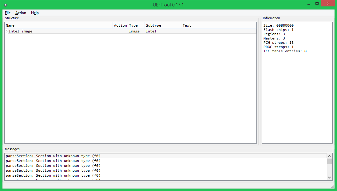
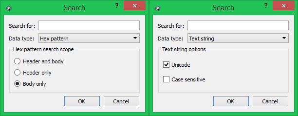
The left part of the window displays the structure of an open image in a tree view, on the right - information about the selected tree item, below - messages indicating errors in the file format, in this case, the use by Phoenix developers of sections of type 0xF0, the purpose of which is not described in the UEFI specification PI . Double-clicking on a message will expand the tree so that it can be seen either on the element itself, which caused this message, or its parent element. Search results are displayed in the same window, which can be called by pressing Ctrl + F (both options with one picture):
Here it is necessary to explain a little terminology. Virtually all structural elements in a UEFI image have a header in which service data such as GUIDs, attributes, checksums, etc., and the body are stored — the actual data is stored in it. The text is not stored in the headers, so for him such a choice is not needed.
At the first level of the tree are the Flash regions, in this case the Descriptor, ME and BIOS:

When choosing a Descriptor region, it is possible to find out access settings to regions, in this case, access is complete, but such settings are very rare. Intel recommends that hardware manufacturers close read / write access to the ME region and the Descriptor region to write, which is why it is almost impossible to remove the full dump on most boards using built-in tools. When selecting a ME region, you can find out the ME firmware version, but if it is not displayed, this is not good and it’s better not to sew such an image.
Let's move one more level to the contents of the BIOS region:
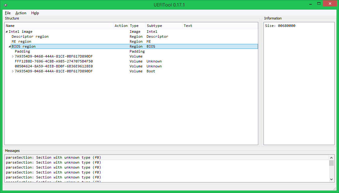
At this level, there are two types of elements: volume and free space. Free in this case is not necessarily empty, for example, the EC firmware is stored in this image at the very beginning of Padding.
Volumes are divided into ordinary (the file system format is known), boot (the FS format is known, contain the Security Core, it is worth changing with extreme caution) and unknown (or the FS format is unknown, or the parsing has not yet been implemented). In our case, the first volume after the free space at the beginning is normal, then two unknowns (in fact, NVRAM is stored in the first, and keys and DB for SecureBoot in the second, but I have not yet explained this to the program), the last volume is bootable .
Now open the regular volume, in this case it stores the files loaded in the DXE phase.
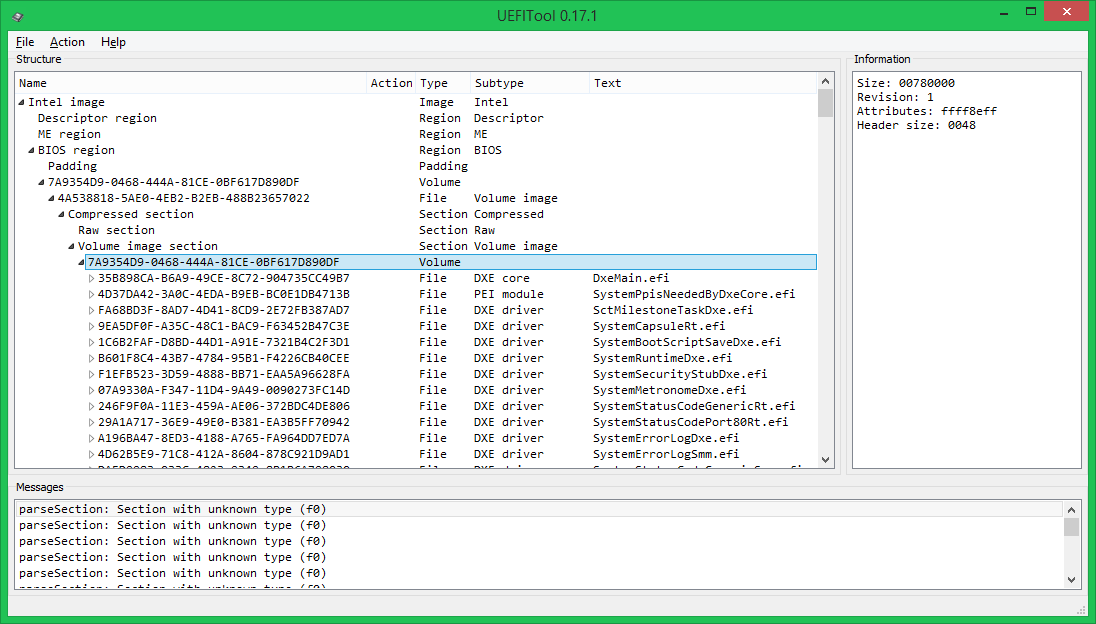
This structure (the main volume inside the compressed section) is used quite often, it allows you to save a decent amount of space in the chip. There is another option to compress not the entire volume, but each file separately - this is somewhat less economical in terms of space, but this UEFI BIOS starts faster, because It makes no sense to unpack files that were not accessed.
Now let's look inside the file:
All data in it is stored inside GUID-defined-sections (in the header of such sections an EDS or a checksum is usually stored, in this case - 4 bytes, similar to the CS, which, however, no one checks), and are divided into 4 sections: the image PE32 is the actual executable file in PE / COFF format, the DXE dependency section defines the order of loading DXE drivers, the UI section contains the text “SystemCapsuleRt.efi” in Unicode format and an unknown section of type 0xF0 (most likely, its contents are This is related to the aforementioned CS).
All this is good, of course, but editing is not yet visible. It does not matter, we call the context menu for any element, which shows what can be done with this element.
And you can do the following:
The last action is the most useful, because allows you to modify any part of the UEFI, without affecting the structure of the entire image.
')
Consider as an example a modification that is useful for MacOS X users on a PC: bypassing the LOCK bit (0x0F) setting in the MSR_PMG_CST_CONFIG_CONTROL (0xE2) register. This bit is set by the PowerManagement DXE driver so that the OS cannot control the CPU multiplier by writing to this register. For Windows and Linux, this is not a big problem, but MacOS X cannot tolerate such impudence from UEFI. You can, of course, patch the AICPM.kext driver (at 10.8) or the kernel (at 10.9), but it is better to patch the DXE driver and not be afraid that the next automatic update will break the download. This patch is needed only for systems based on Intel SandyBridge, IvyBridge and Haswell processors and their * -E variants is done like this:
We flash the resulting image with the same SPI programmer with which it was made, and we get the absence of a kernel panic when booting MacOS X.
If you're wondering where the “75080FBAE80F” magic pattern came from and what other patches you should pay attention to - read the second part of this article, which will be published a little later. In it, I will try to prepare more examples in the format of “what a modification, why it is needed, how to do it, by whom and how it was found”, without delving into each time how to remove the element to be modified and how to insert it back.
I hope that the article did not seem too boring and tedious. If you have questions and suggestions - I will be glad to hear and answer as much as possible. Bug reports will be glad even more. Thanks in advance and successful firmware.
PS Dear administration and personally UFO, make for such posts here the UEFI hub, please.
In my previous articles on UEFI, I planned to describe various useful modifications that help to overcome some of the limitations imposed by manufacturers, but then they did not reach their hands, but now it’s time.
In the first part of this article, I will describe the work with the tool I have written for modifying UEFI images, and the second will be devoted to the modifications themselves.
Entry, disclaimer
UEFI BIOS firmware on modern boards, despite the presence of various technologies like USB BIOS Flashback, Dual BIOS, Flash Recovery, etc. - all the same lottery. The firmware of the modified images is a double lottery.
That is why I ask you to do a full dump of the microcircuit content before starting any experiments with firmware using a hardware SPI programmer, otherwise recovery after a failed firmware (and it will happen sooner or later) will be long, expensive and painful.
An SPI programmer can currently be built at home from anything, from a pair of resistors and capacitors ( SPIPGM ) to an Arduino or Raspberry Pi . My version of a cheap and fast SPI programmer is described here . I advise fans to eliminate a couple of boards to pay attention to this project , and fans of all-in-one devices - to this one .
Further in the text, I believe that you have a programmer, the ability to recover from a firmware failure, and readiness for experiments. Madness of the brave, of course, you can also sing songs, but do not say later that I did not warn you.
Traditionally, everything you read right now is written for educational purposes, the author is not responsible for any damage to your equipment, lost profit, loss of time and faith in humanity, you use the software provided at your own risk and so on.
UEFITool
Tired of the limitations of existing utilities for working with UEFI images (well, and struck by the NIH syndrome at the very heart), I wrote a cross-platform open source utility - UEFITool .
This is the UEFI image editor, written in C ++ \ Qt, distributed under the BSD license, ready-made assemblies are laid out here .
The project is in active development, so the code does not shine with beauty and no bugs, no, yes, they come across. If you suddenly stumble - I will be glad to report.
For normal work with the utility, it is worthwhile to read the previous articles about the structure of the UEFI image, otherwise it will not be clear what is happening at all, but I will try to clarify some points. We assume that this is a blank for future documentation.
As examples in both parts of the article I will use full dumps with Zotac Z77-ITX WiFi (AMI Aptio4) and Dell Vostro 3360 (Phoenix SCT 2.3). Unfortunately, I do not have a test bench on the Insyde H2O platform, so I have nothing to tell about it. Perhaps Falseclock knows a little more about them.
From the point of view of UEFITool, there is practically no difference between the UEFI images from different manufacturers, so I will focus on it when describing patches.
So, run UEFITool, open the image (Ctrl + O) and see something like this:
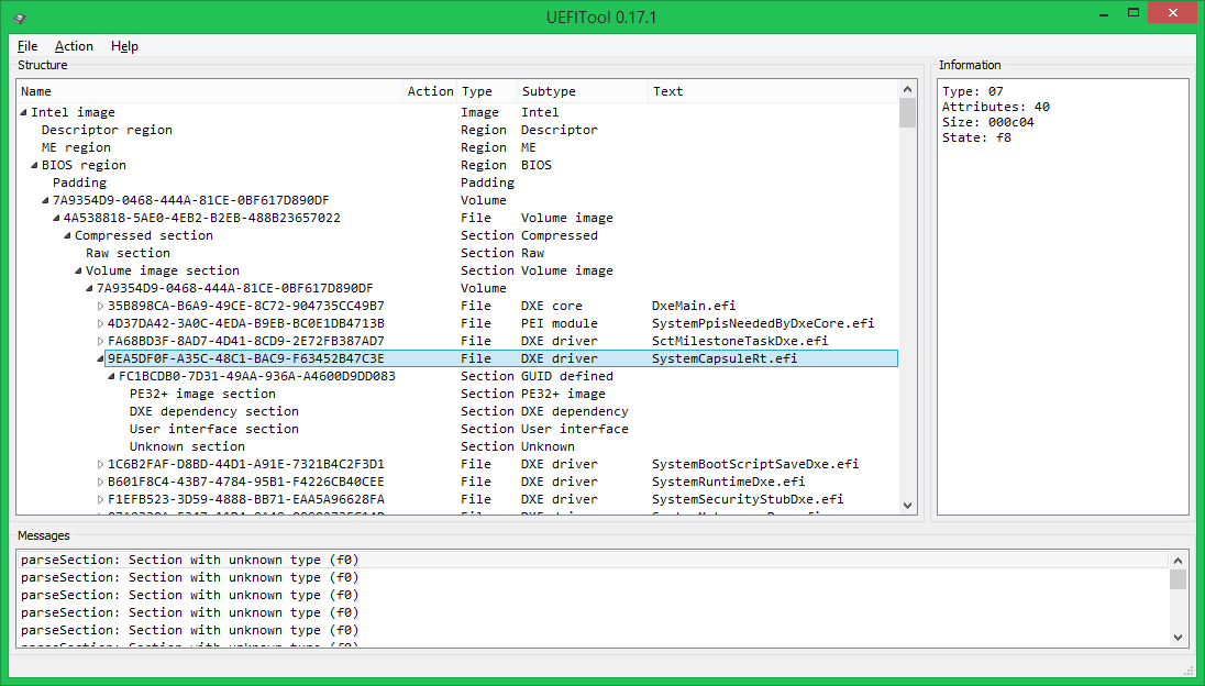
The left part of the window displays the structure of an open image in a tree view, on the right - information about the selected tree item, below - messages indicating errors in the file format, in this case, the use by Phoenix developers of sections of type 0xF0, the purpose of which is not described in the UEFI specification PI . Double-clicking on a message will expand the tree so that it can be seen either on the element itself, which caused this message, or its parent element. Search results are displayed in the same window, which can be called by pressing Ctrl + F (both options with one picture):
Here it is necessary to explain a little terminology. Virtually all structural elements in a UEFI image have a header in which service data such as GUIDs, attributes, checksums, etc., and the body are stored — the actual data is stored in it. The text is not stored in the headers, so for him such a choice is not needed.
At the first level of the tree are the Flash regions, in this case the Descriptor, ME and BIOS:
When choosing a Descriptor region, it is possible to find out access settings to regions, in this case, access is complete, but such settings are very rare. Intel recommends that hardware manufacturers close read / write access to the ME region and the Descriptor region to write, which is why it is almost impossible to remove the full dump on most boards using built-in tools. When selecting a ME region, you can find out the ME firmware version, but if it is not displayed, this is not good and it’s better not to sew such an image.
Let's move one more level to the contents of the BIOS region:
At this level, there are two types of elements: volume and free space. Free in this case is not necessarily empty, for example, the EC firmware is stored in this image at the very beginning of Padding.
Volumes are divided into ordinary (the file system format is known), boot (the FS format is known, contain the Security Core, it is worth changing with extreme caution) and unknown (or the FS format is unknown, or the parsing has not yet been implemented). In our case, the first volume after the free space at the beginning is normal, then two unknowns (in fact, NVRAM is stored in the first, and keys and DB for SecureBoot in the second, but I have not yet explained this to the program), the last volume is bootable .
Now open the regular volume, in this case it stores the files loaded in the DXE phase.
This structure (the main volume inside the compressed section) is used quite often, it allows you to save a decent amount of space in the chip. There is another option to compress not the entire volume, but each file separately - this is somewhat less economical in terms of space, but this UEFI BIOS starts faster, because It makes no sense to unpack files that were not accessed.
Now let's look inside the file:
All data in it is stored inside GUID-defined-sections (in the header of such sections an EDS or a checksum is usually stored, in this case - 4 bytes, similar to the CS, which, however, no one checks), and are divided into 4 sections: the image PE32 is the actual executable file in PE / COFF format, the DXE dependency section defines the order of loading DXE drivers, the UI section contains the text “SystemCapsuleRt.efi” in Unicode format and an unknown section of type 0xF0 (most likely, its contents are This is related to the aforementioned CS).
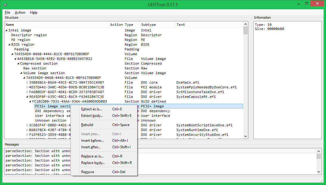
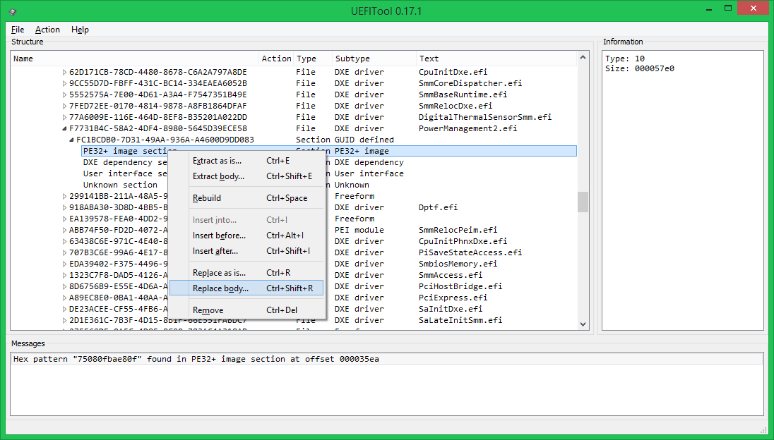
All this is good, of course, but editing is not yet visible. It does not matter, we call the context menu for any element, which shows what can be done with this element.
And you can do the following:
- save element to file either as a whole (Extract as is) or only data, without headers (Extract body)
- rebuild the element (Rebuild), in this case, while saving the changed image, the dimensions (checksums) will be recalculated for it (and all its parent elements), alignment, i.e. the image structure will be aligned with the UEFI PI specification.
- insert an element from a file, either before the selected (Insert before), or after (Insert after), or inside it (Insert into, in this case, nothing will be inserted into the PE32 section)
- replace the element with another element from the file, either entirely (Replace as is), or only its body (Replace body)
The last action is the most useful, because allows you to modify any part of the UEFI, without affecting the structure of the entire image.
')
Usage example
Consider as an example a modification that is useful for MacOS X users on a PC: bypassing the LOCK bit (0x0F) setting in the MSR_PMG_CST_CONFIG_CONTROL (0xE2) register. This bit is set by the PowerManagement DXE driver so that the OS cannot control the CPU multiplier by writing to this register. For Windows and Linux, this is not a big problem, but MacOS X cannot tolerate such impudence from UEFI. You can, of course, patch the AICPM.kext driver (at 10.8) or the kernel (at 10.9), but it is better to patch the DXE driver and not be afraid that the next automatic update will break the download. This patch is needed only for systems based on Intel SandyBridge, IvyBridge and Haswell processors and their * -E variants is done like this:
- Open your dump in UEFITool, clear Messages by pressing Ctrl + Backspace, so as not to interfere
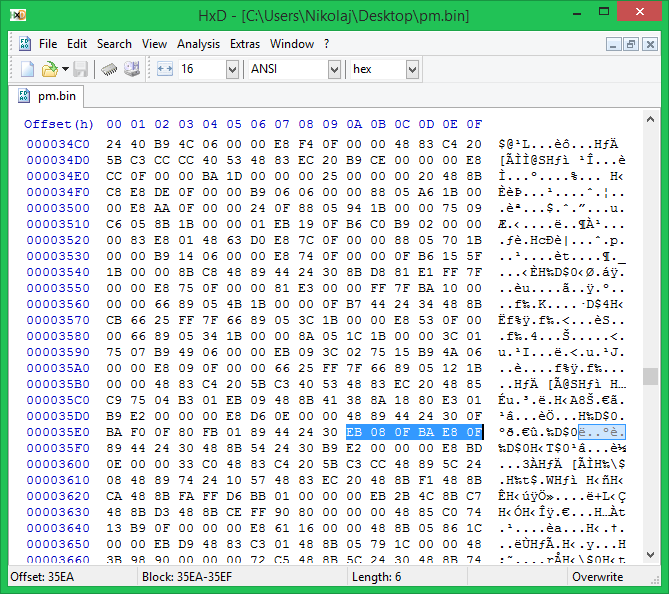
- Open the search, select Hex-pattern, Body only, look for the string "75080FBAE80F"
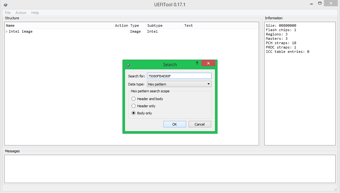
- Double-click on the message that the line is found, save the body of the specified element to the file
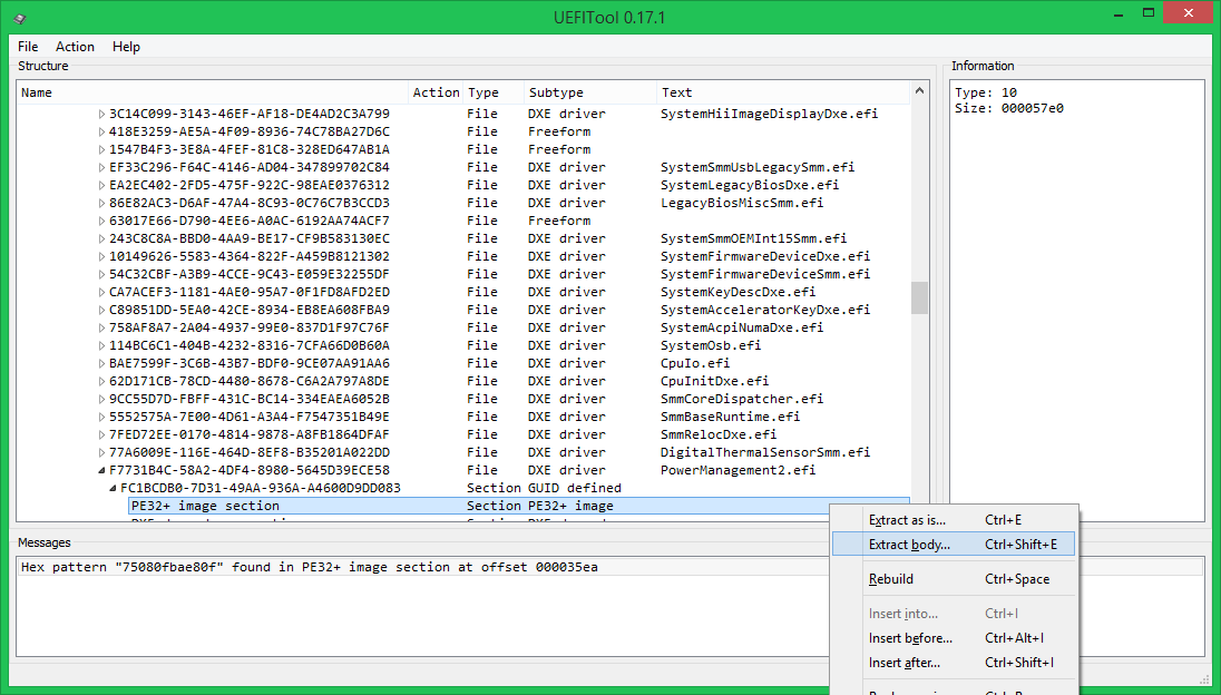
- We fix in Hex-editor “75080FBAE80F” on “EB080FBAE80F” (JE becomes JMP), save the changes
- Replace the contents of the selected element with the changed one, the old element will be marked for deletion (Remove), the new one - with a replacement (Replace), all parent elements up to the root - with a rebuild (Rebuild)
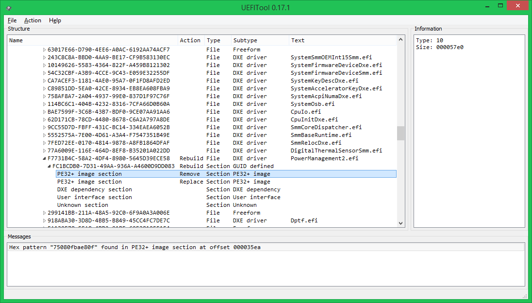
- Save the modified image (Ctrl + S), if the saving was successful, you will be prompted to open the newly saved image, if not - an error message
We flash the resulting image with the same SPI programmer with which it was made, and we get the absence of a kernel panic when booting MacOS X.
Details, other modifications, conclusion
If you're wondering where the “75080FBAE80F” magic pattern came from and what other patches you should pay attention to - read the second part of this article, which will be published a little later. In it, I will try to prepare more examples in the format of “what a modification, why it is needed, how to do it, by whom and how it was found”, without delving into each time how to remove the element to be modified and how to insert it back.
I hope that the article did not seem too boring and tedious. If you have questions and suggestions - I will be glad to hear and answer as much as possible. Bug reports will be glad even more. Thanks in advance and successful firmware.
PS Dear administration and personally UFO, make for such posts here the UEFI hub, please.
Source: https://habr.com/ru/post/211574/
All Articles