Determination of physical constants with the help of STM32 and LED
Introduction
A LED is a semiconductor device that emits electromagnetic waves of the visible or close range. His work is based on the effect of charge carrier recombination in a semiconductor transition with the emission of photons (a full theoretical explanation can be found in the relevant books on physics, it is not described here). The basic electrical and optical properties (for a given construction) are determined by the fundamental physical constants, the indirect measurement of which I will describe in this article. Namely, as a result, the value of the elementary charge (electron charge) and the Planck constant are determined.
I have long wanted to study microcontrollers and understand programming for them, so I decided to do such an experiment. His results were successfully presented as a question of choice in the physics exam a couple of weeks ago.
Microcontroller selection
Since such an idea came to me shortly before the exam, it was necessary to figure out and implement a ready-made working scheme in just a couple of days. I used to have absolutely no experience with microcontrollers, so I chose information from various articles and forums. As a result, I stopped on the 32-bit ARM Cortex family from ST - STM32. There is a rather large assortment of debug boards on such controllers that contain the most necessary things in a convenient form: the processor itself, a simple strapping, a USB debugger (STLink). I took the basic STM32VLDISCOVERY based on the STM32F100RB controller. Key features: 8 KB of RAM, 128 KB of Flash, 24 MHz by default, all ADC / DAC, timers, dozens of GPIO pins, as well as other interfaces. Programs are usually written in C, although of course both assembler and C ++ are possible.
Connect and get started
I didn’t manage to start this device under Linux at the time (then it really worked), so I used the CooCox CoIDE environment for Windows - it has ready-made settings and an example for just such a debugging board like mine. Actually, there were no problems with the connection or with the compilation in it - everything worked right away.
')
To control the processor and peripherals, there is a sufficient choice of libraries: CMSIS from ARM and ST, StdPeriph from ST, library from CooCox and others. In general, now the use of CMSIS seems to be the most correct and even simple for me: it provides definitions of the structures and constants used that correspond to the datasheet. However, since the writing of this project was happening in a hurry, I did not even notice how I used all three of these libraries there :) Of course, knowing the internal structure, you can quite easily transfer all this to the basic CMSIS. Tutorials for the start of development for STM32 and so lacking, so I will not dwell on this anymore.
Schematic diagram
Since the Discovery board is powered by USB (5 V, as well as a 3.3 V stabilizer), the measuring part of the circuit is powered from the same source. Of the additional details - 3 resistors, 1 capacitor, 1 transistor, and of course the LEDs. The electrical circuit is very simple, and I soldered it in a mounted manner - everything kept on the conclusions of the elements:

Here, the switch figuratively indicates the connection to the pin of the controller, to which 0 or 1 is applied. A pull-up to 5 V is used, since in spite of the fact that most pins support the supply of 5 V to them, they can only issue 3.3. Here, respectively, at zero on the pin, the voltage will be 0, and at one - almost 5 V. The capacitor provides a smooth increase and decrease in voltage for a few seconds. The pins labeled "ADC" are connected to any two inputs of the microcontroller's ADC, and provide a measurement of both voltage and current of the LED:

Indication
Of course, you can simply send all the data to a computer, and then process it there, but I wanted to display information on the spot. For this, I used the usual two-line text display like this:

To transfer data to it, 6 GPIO pins are sufficient, and from the software side, the fastest way is to use any library. I took the driver for HD44780 (this is the controller in the display), which connects to CooCox directly from the menu. It’s also easy to write such a driver (which I, by the way, did later), but longer.
Measurements
From the theory of semiconductors it is known (you can read in textbooks) that for small values of the current through the pn junction, as far as saturation is far away, the dependence of the current on voltage is exponential:
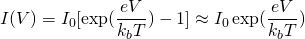 , where I is the current through the transition, I 0 is the current of electrons or holes in the absence of voltage, e is the electron charge, V is the voltage at the transition, k b is the Boltzmann constant, T is the temperature. The last approximate equality is true almost exactly even for sufficiently small voltages (tenths of a volt).
For sufficiently large values of the current, when saturation occurs, the diode can be represented as a series-connected constant voltage drop (equal to the potential transition barrier) and a resistor, which corresponds to the resistance of the semiconductor and the contacts. The potential barrier of the transition in the case of the LED corresponds to the energy of the emitted photons, i.e.
 , where V 0 is the transition voltage, h is Planck's constant, c is the speed of light,
  - The radiation wavelength of the LED. Actually, it is the LED (and not the usual diode) that is needed to determine the wavelength. I took these data from datasheets to LEDs, although in general it can be measured at home - I saw several articles on the creation of a spectrometer based on a CD / DVD disc.
The microcontroller also measures the current-voltage characteristics of the LED, namely, its two sections: low currents and relatively large ones. Measurements are made automatically after pressing the button, when the current increases to 25 milliamperes, and then when it decreases, it returns to zero. For the sections of interest, the CVC controller then calculates the coefficients using the least squares method, and the required constants are obtained from them by simple arithmetic operations.
Typical view of the linear section of the IVC:

And exponential:
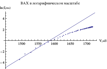
As a result, the values of the determined constants turned out to be very close to real: e = 1.54 * 10 -19 C, h = 5.72 * 10 -34 J * s (average for all available LEDs, a large enough spread).
Programming
I would not like to dwell a lot on writing the code in this case, since a significant part of it, which is responsible for interacting with the periphery, is taken from various articles and tutorials - this is why various libraries are used, and not one :) The article without this turned out to be quite voluminous . Perhaps in the near future I will write a more programming-oriented article, already on a different project based on the same microcontroller.
The entire project (source, CooCox service files, a small report) can be viewed or downloaded at hg.plav.in/stm32_ledcvc/file (the report is in the report folder).
Conclusion
Initially, the goals of this project were achieved: I began to understand the programming of microcontrollers, and also told a question about the choice on the exam :) Of course, some things could be improved or done differently. For example, a smooth change in voltage could be done through a microcontroller DAC, and not a gradual charging of a capacitor — then it would be possible to get along with fewer additional details. And the use of a resistor with a rating of more than 27 Ohms would give more accurate measurements in the range of small currents - but at first I did not plan such measurements, and then it was too late to rework the circuit. By the way, such more accurate measurements may allow for temperature measurement (and in the above scheme, the error would be about + -30 degrees, or even more).
If there are any questions on any part, or there are things that I would like to see in the article related to STM32 programming - write :)
Source: https://habr.com/ru/post/211402/
All Articles