The device of feeding of cats operated, passive AKK-UP-1
The automatic cat feeder mentioned in the Convenient House aroused quite a keen interest, so she is next in line. After all, it is not good to make good people wait, right?
So, the emergence of the Device for feeding cats of a controlled, passive AKK-UP-1 is caused by an urgent need. Which, by the way, manifests itself in the exceptionally whimsical character of one of the caudates living with us in the same house. For a number of reasons of a subjective and objective nature, the said person has taken the habit of demanding food several times a night (and he eats quite a bit of crumbs, as he scoffs). Otherwise, no less nasty moans and plays on the battery.
The situation is complicated by the fact that we can not leave food in constant access, because in the hands of a cat, for the power of which you still need to watch - he is overweight.
')
So, the cat groans, plays on the battery, but there is no strength to get up and feed. What to do? Correct: press the magic red button.
In principle, we are lucky that the diet of one of the cats allows it to be applied to other people's bowls. The main thing is that he does not have unlimited access. This circumstance has seriously simplified the design of the feeder: there is no need to recognize cats.
And since sometimes a naughty cat is in the habit of demanding food literally a quarter of an hour before getting up - and it’s not a fact that he touches the food offered - the feeding trough should at least distract him for these same 15 minutes so that they can safely “sleep”.
Those. needed a unit from the category of "bread and circuses", only for cats.
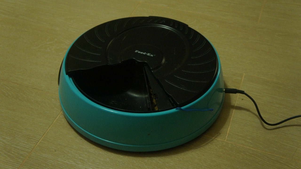
I was lucky - there was a pack bought a long time ago, and quite rarely used automatic feeders Feed-Ex. These feeders are a bowl divided into four sectors. Inside there is also a motor and its own controller, which provides no more than 4 feedings according to a predetermined schedule.
. such a feeder (this is already upgraded)
Feeding is performed by turning the sector with food to a special cutout in the top cover of the feeder. And although it does not matter: the first (or rather, the last) sector, before the first feeding starts, is closed by a special sliding shutter, which moves off at the beginning of this very first feeding. The shutter moves only once, and does not come back - when the tanker is “refilled”, it must be returned to its original position manually.
Such is the factory logic.
Also at hand were: several radio relay and quite a working central controller, which could control including these same relays.
I folded the first and second, and at the same time decided not to fence the garden in the form of a separate controller trough. From here the concept was born. Primitive, but very simple in execution and, as practice has shown, quite effective:
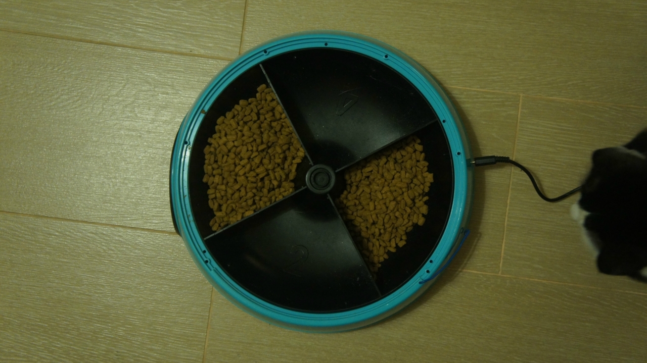
1. Fill the trough sectors in one.
2. Add a radio relay to the food chain of the feeder, parallel to its controller.
3. Add the radio relay control code to the central controller.
4. Upon command, the controller turns on the relay for an interval of time sufficient to rotate the trough one sector.
Thus, each turn of the sector either opens the feed or closes it.
. like this fill the sector with food
The main function of the feeder is to feed cats (or any other small animals) with dry food on command from the console, via the Internet or according to a predetermined schedule without direct (bring-bring) human participation.
The number of feedings is not limited and depends only on the residue of feed in the sections of the feeder.
An additional function of the feeder is switching the cat's attention from banal hooliganism and scandalous behavior to something more constructive. For example, go see what it is in the kitchen buzzing.
Feeding trough:
1. For a specified time, provides animal access to feed by a signal from the remote control
2. For a given time provides access to the animals to feed on command via the Internet.
3. Prevents access to feed at all other times.
4. Provides feed quantity limited only by feed tank.
The feeder does not distinguish between cats, and therefore, if it is open, anyone can eat. The manger also does not know whether the cat has eaten or not, and closes regardless of this. At the same time, the bowl turns slowly enough, which excludes injuries to the animal.
Each time the switch is first turned on, the upgraded manger behaves exactly the same as the usual one: i.e. turns the fourth sector to the notch in the lid. This is its built-in calibration procedure, which works as the proposed upgrade option retains the original functionality of the feeder. In normal operation, the feeder rotates only to the sector at the command of the central controller.
1. When receiving a command from the remote control, the central controller issues a command to turn on the feeder for the time interval required to rotate one sector (this time can be simply measured with a stopwatch).
2. After the turn, a pause of 2.5 minutes is maintained so that the cats have time to reach for something to eat.
3. After a pause, the controller again performs the inclusion of the feeder to turn to the sector. This way the feed is “hidden”.
4. If you press the remote control button again until the pause is over, the controller will immediately issue a command to rotate the feeder to the sector, and the timer rotation will be canceled. This is a “manual” closure procedure in case someone is near the feeder and sees that an illegitimate cat is feeding.
1. When controlling via the Internet, three main commands are available: start a rotation, stop the rotation and execute a turn into a sector.
2. Three service commands are also available: increase the rotation time by 0.5 seconds, reduce the rotation time by 0.5 seconds and bring all the parameters of the feeder to its original state.
Commands for adjusting the rotation time are necessary for more or less precise adjustment of the feeder after it is assembled and launched. The start and stop commands can precisely adjust the edges of the bowl sector to the cutout in the lid.
This adjustment must be repeated periodically, since, due to the floating accuracy of the timer in the Arduino and far from the precision mechanics of the feeder, the boundaries of the sector and the cover gradually "float away" from each other.
This, by the way, is the main disadvantage of my crafts.
For the assembly of the feeder in my version will be needed (links are given for example):
1. Feed-Ex Feeder or equivalent.
2. Learned radio relay 433 MHz 12V or similar, compatible with the library RC-Switch . And the best - immediately to 5V.
3. If the original radio relay is 12V, then the relay is 5V .
4. If, like me, you are not lucky with the receiver in the radio relay, then a 433 MHz receiver with amplitude modulation (ASK / OOK), by reference, a set of receiver and transmitter.
5. Power supply 5V (to taste, the feeder and with batteries can live for some time).
6. Wires and power connectors (connectors are useful if you want external power).
So, you have a working radio relay on 433 MHz and 5V. Then the assembly procedure is simple, but a bit dreary for my taste.
To do this, we use the instructions for the relay, our own intelligence, or, if your relay is mine, then something intermediate between the first two options.
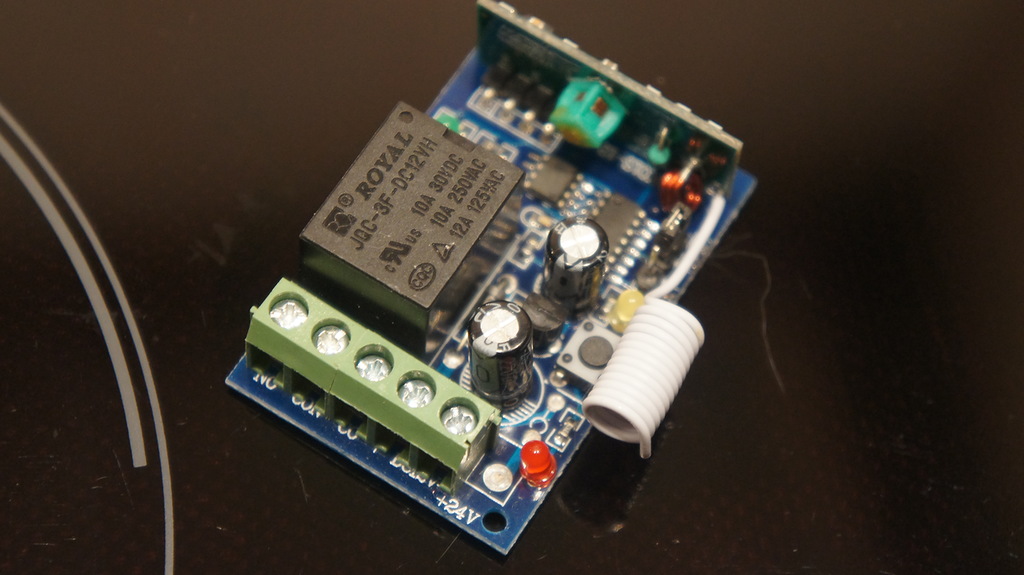
The purpose of the light bulbs is recognized simply: red LED - power, yellow - learning, green - relay operation.
The relay has three modes of operation, which are switched by a jumper on the board:
1) Enabled while the remote control button is pressed (without jumper)
2) Switching states with one remote button (one press - on, second - off - and in a circle) (jumper on the left)
3) Switching states with two buttons (one button turns on, the other turns it off) (jumper on the right)
For the feeder, it is required to transfer the relay to the third mode, i.e. one button on the remote, and the shutdown - the other. Switching the mode must be performed when the relay is off, otherwise it will no longer understand what is happening.
. the picture shows the position of the jumper and the receiver

Binding to the console (controller) is simple:
1) Press and hold the only button for programming the relay until the yellow LED goes out.
2) Briefly press the relay programming button
3) Press the button on the remote control (send a command through the controller) to which you want to bind the relay.
In all modes, just press one button on the remote control. Even in the third, because the controller has a hard logic relay: it “iron” calculates the second control combination on the basis of the great Chinese algorithm.
The bottom line is that the management team is a certain number (for example, 380242). In this case, the off command is one less than the on command (380241). As a result, the relay controller reads the received code as an enable code and subtracts a unit for the off code from it.
Since we mean the controller under the remote control, then we can use a simple sketch to train the relay:
When the relay is ready, you can embed it in the feeder.
1. First, remove the cover, then remove the bowl, then turn over the feeder and unscrew all the screws - and under the legs, and under the batteries. There are no latches, so if the upper part of the feeder is not removed - it means that not all screws were unscrewed.
2. If you want to keep the original functionality of the feeder, then you need a diode such as 1N4007 (if you drop the diode from the radio relay, it will work). If you do not want - you can immediately unsolder the controller from the power supply and the feeder, just remember the polarity of the wiring.
3. From the feeder batteries and from its controller to the motor go two wires: black - minus, red - plus. In this case, the positive wire from the battery goes to the power switch.
4. We connect to the power supply the relay minus from the battery compartment and plus after the power switch. That is, so that the relay is turned on simultaneously with the inclusion of the feeder.
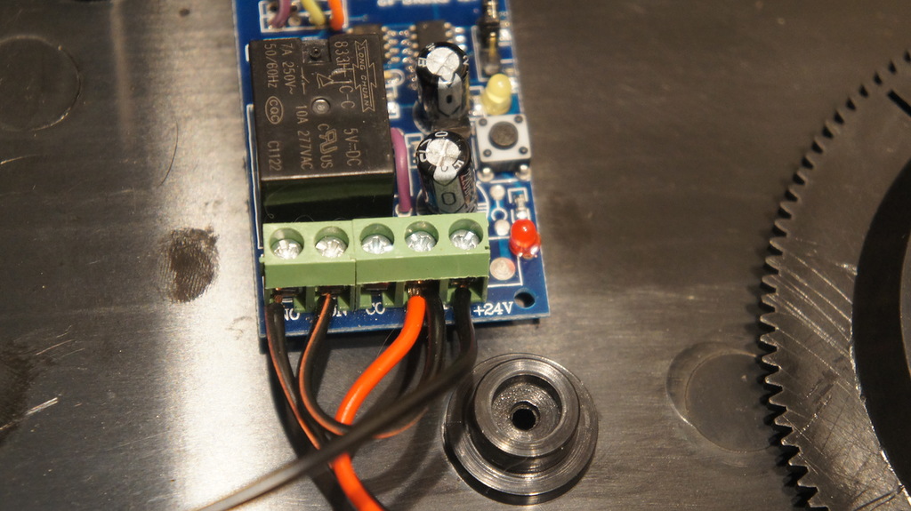
5. Plus, from the power supply of the relay, we also switch to one of the normally open contacts of the relay (NO or COM). The second contact (NO or COM, respectively) is connected to the motor, having previously unsoldered the “native” positive lead of the controller from it.
. relay switching
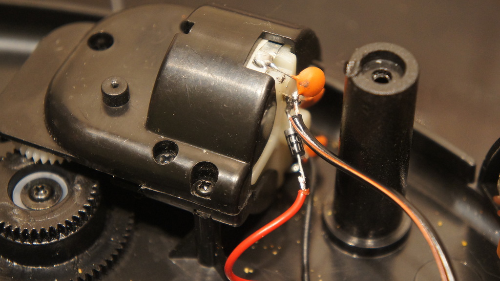
6. The plus wire from the controller is soldered to the positive terminal of the motor through the diode. According to my idea, this trick will prevent the voltage from the relay from reaching the controller output. Whether it is important or not, I don’t know, but I did it just in case. Negative wire motor does not touch.
. motor connection
The result should be something like this:
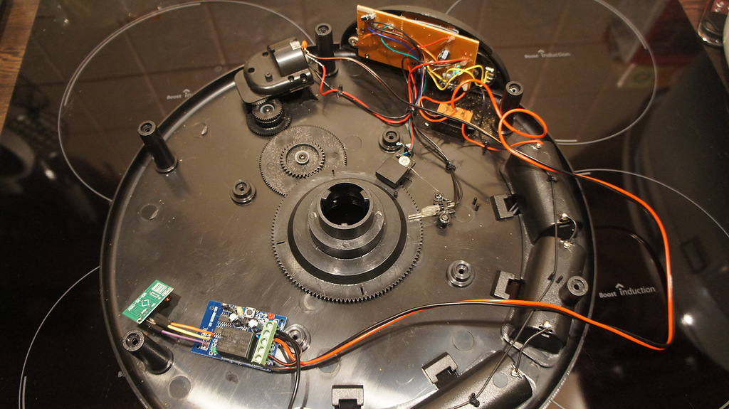
You see - the controller was not injured.
7. Optionally, we put the external power connector, just parallel to the contacts of the battery compartment. Those. minus connector - to the minus of the battery compartment, plus - to the plus.
In principle, this is a good option, as the rotational speed of the motor, and hence the time to turn the sector will not depend on the discharge of the batteries, and the feeder does not require calibration for longer.
8. Check the operation of the feeder using, for example, the same sketch. If it turns on - great. You can change the command to the shutdown command, and run the sketch again. If it turns off - even better, then everything works.
9. And if everything works, we fix the relay and receiver board (if it hangs separately) in the trough box and assemble it.
So I checked the feeder with remote control:
For the role of this device, I took the usual "Panic" button from the wireless Chinese alarm system. In fact, it’s just a one-button remote control. You can use anything that you have free from similar devices compatible with the above mentioned RC-Switch library.
This is exactly the button, at the command from which the controller turns the feeder into a sector, waits 2.5 minutes, and then turns it further into a sector. Or close the feeder immediately, if the button is pressed again before the timeout expires.
. big red button
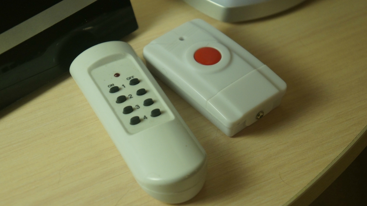
To operate a button, you must read its code, and make it easier than ever. It is only necessary to load the sample ReceiveDemo_Simple from the RC-Switch kit into Arduino, open the terminal and press the remote control button. The resulting numeric combination is the button code, which you then insert into the control code.
With my button, however, there was a small problem. Well, or with a receiver controller. It turned out that on the bed - almost the limit of the button. Perhaps you are more lucky, and I eventually added the command repeater function to one of the service controllers (it is halfway between the button and the central controller). And it all worked like a clock.
So, we got a trough. Not very smart, but very executive: if you say, it will turn, it will turn. If you say stop, stop. On the other hand, why are we smart? We have a central controller - let him think.
The feeding trough algorithm, described above, is defined in the controller’s program (it’s at the end of the text, the Controller is the central home, all-powerful CCD-B-2-12 , and it’s convenient to look for the feeding functions using the feed word) is determined by the following functions and code fragments:
And one of the branches of radio commands, dedicated to the reaction to the button on the remote:
Honestly, when you do it all, it doesn't look that difficult. But as I begin to describe, I get an exposition, from which except that the blood in my veins does not get cold.
It may seem that this is quite a stupid design - in some way it is. It may seem that periodically adjusting the position of the bowl is a monkey job and it would be possible to put a controller inside it with a sector position sensor. However, this no longer seems - it is really possible, and you can do it.
But in fact, even in such an implementation, the trough was quite convenient and useful. And all this, I repeat, really works. And the seals do not complain.
If you make a mistake somewhere - signal, we will fix it together!
So, the emergence of the Device for feeding cats of a controlled, passive AKK-UP-1 is caused by an urgent need. Which, by the way, manifests itself in the exceptionally whimsical character of one of the caudates living with us in the same house. For a number of reasons of a subjective and objective nature, the said person has taken the habit of demanding food several times a night (and he eats quite a bit of crumbs, as he scoffs). Otherwise, no less nasty moans and plays on the battery.
The situation is complicated by the fact that we can not leave food in constant access, because in the hands of a cat, for the power of which you still need to watch - he is overweight.
')
So, the cat groans, plays on the battery, but there is no strength to get up and feed. What to do? Correct: press the magic red button.
Other devices and devices of the series
Introductory
In principle, we are lucky that the diet of one of the cats allows it to be applied to other people's bowls. The main thing is that he does not have unlimited access. This circumstance has seriously simplified the design of the feeder: there is no need to recognize cats.
And since sometimes a naughty cat is in the habit of demanding food literally a quarter of an hour before getting up - and it’s not a fact that he touches the food offered - the feeding trough should at least distract him for these same 15 minutes so that they can safely “sleep”.
Those. needed a unit from the category of "bread and circuses", only for cats.
I was lucky - there was a pack bought a long time ago, and quite rarely used automatic feeders Feed-Ex. These feeders are a bowl divided into four sectors. Inside there is also a motor and its own controller, which provides no more than 4 feedings according to a predetermined schedule.
. such a feeder (this is already upgraded)
Feeding is performed by turning the sector with food to a special cutout in the top cover of the feeder. And although it does not matter: the first (or rather, the last) sector, before the first feeding starts, is closed by a special sliding shutter, which moves off at the beginning of this very first feeding. The shutter moves only once, and does not come back - when the tanker is “refilled”, it must be returned to its original position manually.
Such is the factory logic.
Also at hand were: several radio relay and quite a working central controller, which could control including these same relays.
I folded the first and second, and at the same time decided not to fence the garden in the form of a separate controller trough. From here the concept was born. Primitive, but very simple in execution and, as practice has shown, quite effective:
1. Fill the trough sectors in one.
2. Add a radio relay to the food chain of the feeder, parallel to its controller.
3. Add the radio relay control code to the central controller.
4. Upon command, the controller turns on the relay for an interval of time sufficient to rotate the trough one sector.
Thus, each turn of the sector either opens the feed or closes it.
. like this fill the sector with food
Purpose of AKK-UP-1
The main function of the feeder is to feed cats (or any other small animals) with dry food on command from the console, via the Internet or according to a predetermined schedule without direct (bring-bring) human participation.
The number of feedings is not limited and depends only on the residue of feed in the sections of the feeder.
An additional function of the feeder is switching the cat's attention from banal hooliganism and scandalous behavior to something more constructive. For example, go see what it is in the kitchen buzzing.
Functions AKK-UP-1
Feeding trough:
1. For a specified time, provides animal access to feed by a signal from the remote control
2. For a given time provides access to the animals to feed on command via the Internet.
3. Prevents access to feed at all other times.
4. Provides feed quantity limited only by feed tank.
Algorithm work
The feeder does not distinguish between cats, and therefore, if it is open, anyone can eat. The manger also does not know whether the cat has eaten or not, and closes regardless of this. At the same time, the bowl turns slowly enough, which excludes injuries to the animal.
Each time the switch is first turned on, the upgraded manger behaves exactly the same as the usual one: i.e. turns the fourth sector to the notch in the lid. This is its built-in calibration procedure, which works as the proposed upgrade option retains the original functionality of the feeder. In normal operation, the feeder rotates only to the sector at the command of the central controller.
When controlling the remote control
1. When receiving a command from the remote control, the central controller issues a command to turn on the feeder for the time interval required to rotate one sector (this time can be simply measured with a stopwatch).
2. After the turn, a pause of 2.5 minutes is maintained so that the cats have time to reach for something to eat.
3. After a pause, the controller again performs the inclusion of the feeder to turn to the sector. This way the feed is “hidden”.
4. If you press the remote control button again until the pause is over, the controller will immediately issue a command to rotate the feeder to the sector, and the timer rotation will be canceled. This is a “manual” closure procedure in case someone is near the feeder and sees that an illegitimate cat is feeding.
When managing via the Internet
1. When controlling via the Internet, three main commands are available: start a rotation, stop the rotation and execute a turn into a sector.
2. Three service commands are also available: increase the rotation time by 0.5 seconds, reduce the rotation time by 0.5 seconds and bring all the parameters of the feeder to its original state.
Commands for adjusting the rotation time are necessary for more or less precise adjustment of the feeder after it is assembled and launched. The start and stop commands can precisely adjust the edges of the bowl sector to the cutout in the lid.
This adjustment must be repeated periodically, since, due to the floating accuracy of the timer in the Arduino and far from the precision mechanics of the feeder, the boundaries of the sector and the cover gradually "float away" from each other.
This, by the way, is the main disadvantage of my crafts.
Iron
For the assembly of the feeder in my version will be needed (links are given for example):
1. Feed-Ex Feeder or equivalent.
2. Learned radio relay 433 MHz 12V or similar, compatible with the library RC-Switch . And the best - immediately to 5V.
3. If the original radio relay is 12V, then the relay is 5V .
4. If, like me, you are not lucky with the receiver in the radio relay, then a 433 MHz receiver with amplitude modulation (ASK / OOK), by reference, a set of receiver and transmitter.
5. Power supply 5V (to taste, the feeder and with batteries can live for some time).
6. Wires and power connectors (connectors are useful if you want external power).
IF YOU HAVE A 12V RELAY OR A FAILED RELAY RECEIVER
Main symptoms: you are trying to switch it (relay), but it does not switch. Or does it at a distance of ten centimeters from the transmitter, and no further.
I had several relays, and, having tried one, I thought it was a defective copy. But when the second behaved in the same way, it became clear that something was wrong in the Chinese Empire. One competent comrade suggested that they sent me a relay at 315 MHz, and near the 433 MHz transmitter it switched according to the principle of “wind blew”. In general, I agree with him, but I did not bother to test this hypothesis in practice.
The solution to the problem is quite simple: it is quite clear from the receiver on the relay board that there is a plus, a ground, and a data output. Actually, we solder to the corresponding places (you can even solder in place of the native one) a new proven 433 MHz receiver. And that's all, the problem is solved.
The feeder is powered by 6V, and the relay is 12V. The power for the feeder is too low for the relay, and the power for the relay is too much for the feeder. What do we do?
First, look thoughtfully at the relay board. I found right here, on the plus input of the power supply, some incomprehensible detail, which eventually turned out to be a diode protecting the circuit from reverse polarity. And on the same diode a rather noticeable voltage drop occurs. Therefore, I promised myself that I would connect strictly plus to plus, and minus to minus, I dropped out a diode and made a transition to it.
It became a little more fun - in the sense of the power indicator, the relay turned on brighter, but it didn’t change the essence: the relay logic worked, and the relay did not switch. All the same, too little voltage.
I solved this problem radically: I changed the 12V relay to the same size and wiring of the relay contacts with a coil voltage of 5V. And it all worked. Hence the scheme:
1. If your relay is the same diode - you can vypayat and perekknut.
2. The original 12V relay must be replaced with a 5V relay.
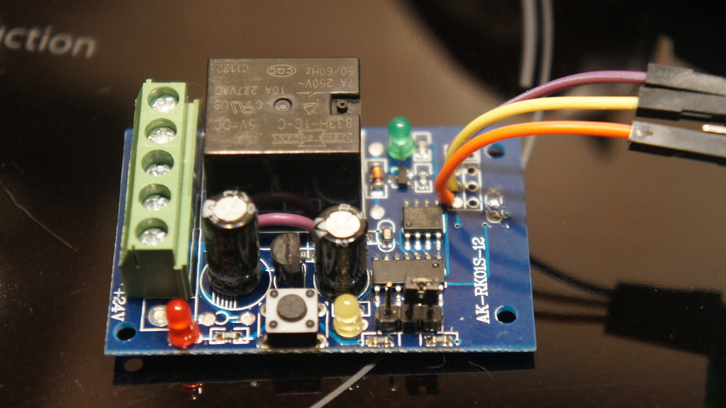
. this picture clearly shows the relay
. but on this one there is a diode: to the left of the relay site, between electrolytic capacitors
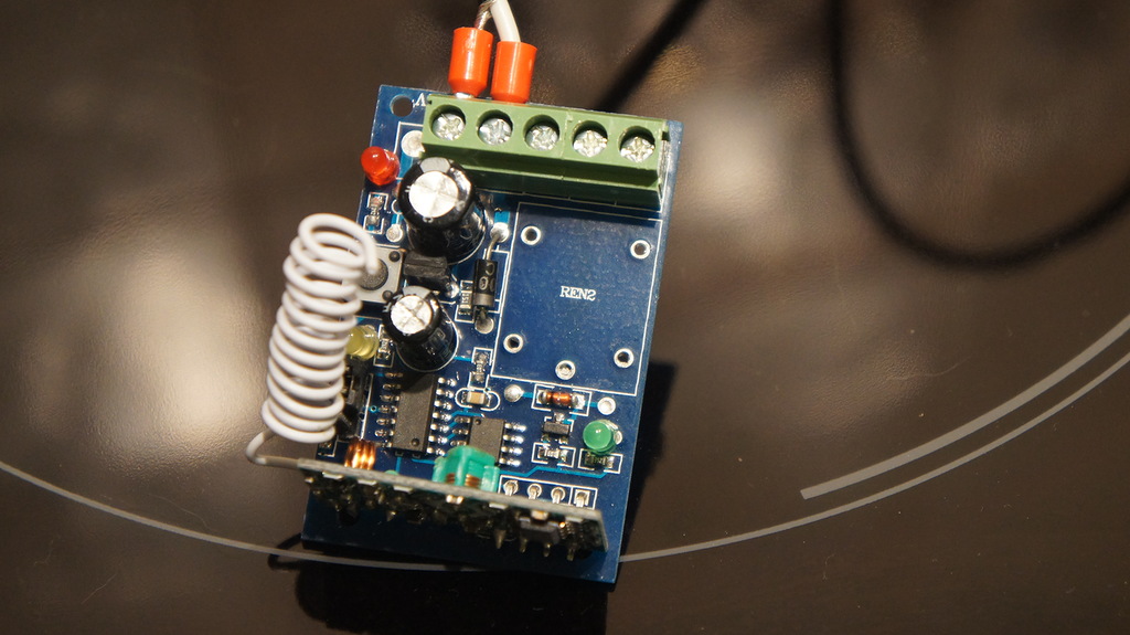
. there is already a jumper (lilac) instead of a diode, a new relay and a new receiver on the wiring
If you are not lucky with the receiver in the radio relay
Main symptoms: you are trying to switch it (relay), but it does not switch. Or does it at a distance of ten centimeters from the transmitter, and no further.
I had several relays, and, having tried one, I thought it was a defective copy. But when the second behaved in the same way, it became clear that something was wrong in the Chinese Empire. One competent comrade suggested that they sent me a relay at 315 MHz, and near the 433 MHz transmitter it switched according to the principle of “wind blew”. In general, I agree with him, but I did not bother to test this hypothesis in practice.
The solution to the problem is quite simple: it is quite clear from the receiver on the relay board that there is a plus, a ground, and a data output. Actually, we solder to the corresponding places (you can even solder in place of the native one) a new proven 433 MHz receiver. And that's all, the problem is solved.
If you have a 12V relay
The feeder is powered by 6V, and the relay is 12V. The power for the feeder is too low for the relay, and the power for the relay is too much for the feeder. What do we do?
First, look thoughtfully at the relay board. I found right here, on the plus input of the power supply, some incomprehensible detail, which eventually turned out to be a diode protecting the circuit from reverse polarity. And on the same diode a rather noticeable voltage drop occurs. Therefore, I promised myself that I would connect strictly plus to plus, and minus to minus, I dropped out a diode and made a transition to it.
It became a little more fun - in the sense of the power indicator, the relay turned on brighter, but it didn’t change the essence: the relay logic worked, and the relay did not switch. All the same, too little voltage.
I solved this problem radically: I changed the 12V relay to the same size and wiring of the relay contacts with a coil voltage of 5V. And it all worked. Hence the scheme:
1. If your relay is the same diode - you can vypayat and perekknut.
2. The original 12V relay must be replaced with a 5V relay.
. this picture clearly shows the relay
. but on this one there is a diode: to the left of the relay site, between electrolytic capacitors
. there is already a jumper (lilac) instead of a diode, a new relay and a new receiver on the wiring
So, you have a working radio relay on 433 MHz and 5V. Then the assembly procedure is simple, but a bit dreary for my taste.
1. Let's program the relay to our teams.
To do this, we use the instructions for the relay, our own intelligence, or, if your relay is mine, then something intermediate between the first two options.
The purpose of the light bulbs is recognized simply: red LED - power, yellow - learning, green - relay operation.
The relay has three modes of operation, which are switched by a jumper on the board:
1) Enabled while the remote control button is pressed (without jumper)
2) Switching states with one remote button (one press - on, second - off - and in a circle) (jumper on the left)
3) Switching states with two buttons (one button turns on, the other turns it off) (jumper on the right)
For the feeder, it is required to transfer the relay to the third mode, i.e. one button on the remote, and the shutdown - the other. Switching the mode must be performed when the relay is off, otherwise it will no longer understand what is happening.
. the picture shows the position of the jumper and the receiver
Binding to the console (controller) is simple:
1) Press and hold the only button for programming the relay until the yellow LED goes out.
2) Briefly press the relay programming button
3) Press the button on the remote control (send a command through the controller) to which you want to bind the relay.
In all modes, just press one button on the remote control. Even in the third, because the controller has a hard logic relay: it “iron” calculates the second control combination on the basis of the great Chinese algorithm.
The bottom line is that the management team is a certain number (for example, 380242). In this case, the off command is one less than the on command (380241). As a result, the relay controller reads the received code as an enable code and subtracts a unit for the off code from it.
Since we mean the controller under the remote control, then we can use a simple sketch to train the relay:
SKETCH
Here you need an 433 MHz ASK / OOK transmitter (for example, from this kit ), connected to 10 pin Arduino (or you can reassign). The sketch transmits the same command with an interval of 5 seconds, so if you fail to program the relay the first time, it doesn't matter. Just put it back into training mode (starting from step 1. binding instructions) and wait for the relay to accept and remember the command.
Just in case, the relay and transmitter are better positioned next to each other.
Just in case, the relay and transmitter are better positioned next to each other.
#include <RCSwitch.h> RCSwitch mySwitch = RCSwitch(); void setup() { // Transmitter is connected to Arduino Pin #10 mySwitch.enableTransmit(10); } void loop() { /* Same switch as above, but using decimal code */ mySwitch.send(380242, 24); delay(5000); } When the relay is ready, you can embed it in the feeder.
2. Operation on the feeder
1. First, remove the cover, then remove the bowl, then turn over the feeder and unscrew all the screws - and under the legs, and under the batteries. There are no latches, so if the upper part of the feeder is not removed - it means that not all screws were unscrewed.
2. If you want to keep the original functionality of the feeder, then you need a diode such as 1N4007 (if you drop the diode from the radio relay, it will work). If you do not want - you can immediately unsolder the controller from the power supply and the feeder, just remember the polarity of the wiring.
3. From the feeder batteries and from its controller to the motor go two wires: black - minus, red - plus. In this case, the positive wire from the battery goes to the power switch.
4. We connect to the power supply the relay minus from the battery compartment and plus after the power switch. That is, so that the relay is turned on simultaneously with the inclusion of the feeder.
5. Plus, from the power supply of the relay, we also switch to one of the normally open contacts of the relay (NO or COM). The second contact (NO or COM, respectively) is connected to the motor, having previously unsoldered the “native” positive lead of the controller from it.
. relay switching
6. The plus wire from the controller is soldered to the positive terminal of the motor through the diode. According to my idea, this trick will prevent the voltage from the relay from reaching the controller output. Whether it is important or not, I don’t know, but I did it just in case. Negative wire motor does not touch.
. motor connection
The result should be something like this:
You see - the controller was not injured.
7. Optionally, we put the external power connector, just parallel to the contacts of the battery compartment. Those. minus connector - to the minus of the battery compartment, plus - to the plus.
In principle, this is a good option, as the rotational speed of the motor, and hence the time to turn the sector will not depend on the discharge of the batteries, and the feeder does not require calibration for longer.
8. Check the operation of the feeder using, for example, the same sketch. If it turns on - great. You can change the command to the shutdown command, and run the sketch again. If it turns off - even better, then everything works.
9. And if everything works, we fix the relay and receiver board (if it hangs separately) in the trough box and assemble it.
So I checked the feeder with remote control:
Magic red button
For the role of this device, I took the usual "Panic" button from the wireless Chinese alarm system. In fact, it’s just a one-button remote control. You can use anything that you have free from similar devices compatible with the above mentioned RC-Switch library.
This is exactly the button, at the command from which the controller turns the feeder into a sector, waits 2.5 minutes, and then turns it further into a sector. Or close the feeder immediately, if the button is pressed again before the timeout expires.
. big red button
To operate a button, you must read its code, and make it easier than ever. It is only necessary to load the sample ReceiveDemo_Simple from the RC-Switch kit into Arduino, open the terminal and press the remote control button. The resulting numeric combination is the button code, which you then insert into the control code.
With my button, however, there was a small problem. Well, or with a receiver controller. It turned out that on the bed - almost the limit of the button. Perhaps you are more lucky, and I eventually added the command repeater function to one of the service controllers (it is halfway between the button and the central controller). And it all worked like a clock.
Soft
So, we got a trough. Not very smart, but very executive: if you say, it will turn, it will turn. If you say stop, stop. On the other hand, why are we smart? We have a central controller - let him think.
The feeding trough algorithm, described above, is defined in the controller’s program (it’s at the end of the text, the Controller is the central home, all-powerful CCD-B-2-12 , and it’s convenient to look for the feeding functions using the feed word) is determined by the following functions and code fragments:
void feedOn() { // if (feedB == false) { // txSwitch(380242); // feedB = true;} // , } void feedOff() { // if (feedB == true) { txSwitch(380241); feedB = false;} } void feedAuto() { // , feedTimer feedOn(); myTime.setTimeout(feedTimer, feedOff); // ( <a href="http://playground.arduino.cc/Code/SimpleTimer">SimpleTimer</a>) feedOff feedTimer } void feedClose() { // feedAuto(); // turnIt = false; // } And one of the branches of radio commands, dedicated to the reaction to the button on the remote:
case 15741424: // mySwitch.disableReceive(); if (feedB == false) { // tone(9, 400, 450); // - if (aCl == true) { // if (turnIt == true) { // myTime.deleteTimer(feedID); // feedAuto(); // turnIt = false; // } else { // feedAuto(); // feedID=myTime.setTimeout(150000+feedTimer, feedClose); // (150000 - , ) turnIt = true; // } } else { feedAuto(); } } mySwitch.enableReceive(0); break; Instead of conclusion
Honestly, when you do it all, it doesn't look that difficult. But as I begin to describe, I get an exposition, from which except that the blood in my veins does not get cold.
It may seem that this is quite a stupid design - in some way it is. It may seem that periodically adjusting the position of the bowl is a monkey job and it would be possible to put a controller inside it with a sector position sensor. However, this no longer seems - it is really possible, and you can do it.
But in fact, even in such an implementation, the trough was quite convenient and useful. And all this, I repeat, really works. And the seals do not complain.
If you make a mistake somewhere - signal, we will fix it together!
Source: https://habr.com/ru/post/211234/
All Articles