The controller is a central home, all-powerful KCD-V-2-12
The history of the birth of the central home controller is quite confusing. It seems to me that if you take a break for a second and present it in the form of a winter forest (view from above), then you can see random paths, poorly camouflaged pits and, possibly, I. Susanin wandering somewhere in the wilderness.
Functionality increased gradually: first I connected the wireless sockets, then swung at the light switches. Appetites grew - leaking sensors, smoke, doors, weather sensors, radio relay and control AV-technology. Mastery did not grow so fast. Therefore, it turned out what happened: a thing infinitely far from the guidelines on programming and electronic circuits, but quite workable.
And you know what? It suits me.
')
If you suddenly missed the content of the first series, just in case I remind you . This text will not be as incendiary, since more instructions. In addition, at the very beginning I am planning a large-scale "disclaimer of warranties". The fact is that I am extremely far from both circuitry and programming. Therefore, what I did turned out exactly as it happened (I wanted to use even more, but it did not work).
I, of course, will try to answer the questions "why so and not so?", But in many cases it will look like if you asked the blonde why she turned on the right turn signal and left the rightmost row of her strip to the extreme right row counter. Practically everything that now exists acts on the fundamental principle “Does it work? Do not touch!".
For the same reason, I will show the code and scheme in the original configuration with the minimum possible changes (mainly anonymization of personal data). It should, with a high degree of probability, allow it to be repeated in working condition. And then you can comb and decorate everything as you like. Unless, of course, want to repeat.
Please understand that I have not reached the modification of Arduino to download sketches through a local network. And any modification of the code turns around running around with stools and a headache with the return to working condition of the motion sensor. Therefore, I will a priori be hostile to perceive even worthwhile sentences. Most likely, then I will chill and not only take note, but also implement your advice.
Therefore, I apologize in advance for possible violent reaction.
So, the central controller. To begin, I will repeat its functions:
1) Management of four radio sockets;
2) Control of 8 buttons of four radio light switches;
3) Reboot the router when the Internet is lost;
4) Turn on and off the webcam;
5) Monitoring 8 wireless sensors OPS (three smoke sensors, three leak sensors, a pair of door opening sensors);
6) Receive data from two meteorological sensors and transfer them to the Internet;
7) Control TV, media player and air conditioning;
8) Manage the cat feeder;
9) Monitoring the wired motion sensor;
10) Event notification by email.
Service functions (scripts):
1) Automatic control of light in the wardrobe;
2) Automatic control of the light in the hallway;
3) Automatic control of night lighting in the kitchen;
4) Automatic control of light and music in the bathroom (at the time of writing - two options: by the controller itself and the commands to the controller in the bathroom);
5) Turning off everything that turns off remotely, turning on the camera and switching the motion sensor to protection mode when leaving home; and turning off the camera with turning on the background light, the light in the hallway and switching the motion sensor to the previous one, before guarding, on return.
Paradoxically, the central controller is connected directly to two network adapters, which is associated with different supply voltages of the webcam and router it controls.
In other words, block 9B feeds the controller, and its relay is switched to power the router, and block 5B is used to power the webcam and peripheral auxiliary power, because the Arduino lacks all the outputs and capabilities.
Already now I understand that one sufficiently powerful 9V block and one 5V stabilizer would be enough. And maybe later I'll come back to this. And you can immediately remove the extra piece of iron from the list.
By the way, curiously, I only now realized the whole tragic idiocy of the situation. Blonde, in short.
To prepare the controller you will need (links only for an example):
1) Arduino Uno - 1 pc.
2) Ethernet Shield with Wiznet W5100 chip - 1 pc.
3) ASK / OOK receiver 433 MHz - 1 pc.
4) 433 MHz ASK / OOK transmitter - 1 pc.
5) Motion sensor HC-SR501 - 1 pc.
6) Block (at least 2 pcs. In the block) 5V relay with keys - 1 pc.
7) Piezoceramic squeaker - 1 pc.
8) Power sources. At least - 5V for Arduino and its periphery. Better - 9V and stabilizer 5V for the periphery.
9) Antennas for receiver and transmitter, if they are not.
10) Dummy or other wires, connectors and housing to taste.
Basically, there are no problems with the selection of components. The most critical are the receiver, the transmitter ( usually sold in sets ) and their antennas. In my opinion, apart from the price, there is no particular difference between superregenerative and superheterodyne receivers (maybe I do not know how to prepare them).
. conventional transmitter. The inscription in defocus reads FS1000A

True, I liked the transmitter, bought on the occasion of the DX . He, in addition to being more expensive than others, is already equipped with a spiral antenna and subjectively works better than very cheap transmitters, which I tried to equip with home-made and spiral "factory" antennas .
. the usual superregenerative receiver, to which I have already managed to solder the “antenna”

But the superheterodyne receiver bought in the same place, as I said above, was not impressed.
To the question of antennas, by the way, I'll be back - I had a very sore point. In the meantime, let me remind you that cheap receiver and transmitter kits are sold without antennas. And this does not mean that it should be so. This means that you will have to either make the antennas yourself, or buy ready-made ones.
Piezoceramic tweeter got this place because it does not need additional components. Internal resistance allows you to connect directly to the Arduino. And it also screams quite loudly and is very compact.
And in order not to get up two times: Arduino Uno because I chose the first controller. For the same reason - network shild with W5100. After all, judging by the then opinion, these were the best things for beginners. I did not know that everything would go so far.
. Shield does not interfere at all to assemble a prototype

The purpose of the components is quite transparent. Ethernet-Shield provides the web server on the Arduino and, accordingly, remote management, configuration and status monitoring. The receiver listens to the sensors, the transmitter sends controller commands to the actuators (sockets, switches) and service controllers.
A motion sensor attached to the controller is used for security modes and automatic light control. A squeaker informs about successful activation, reception of some radio commands (for example, confirms that it heard the power button on the feeder so as not to press it until complete and final satisfaction) and is used to set up the same motion sensor (the warning when the sensor is triggered helps to set the direction sensitivity and identify false positives).
The relays turn on and off the router and the webcam, which is very important if you consider that my router is hidden not only out of sight, but also at a height higher than my height. The result is a reboot of the network without problems and the physical shutdown of the camera when it is not in use, which gives some psychological comfort.
. convenient relay unit with direct connection to the Arduino. It is simply impossible to connect the relay - the current consumed by the coil is too large. And here on the board optocoupler and a transistor switch plus a status LED

The controller assembly is nothing extraordinary. Only, of course, do not forget to fasten the Ethernet shield on the Arduino Uno right away and remember that the network shield uses the 4, 10, 11, 12 and 13 Arduino Uno pins, so they are not used in the controller functions. Fortunately, Uno has enough digital pins and a full set of analog ones.
The current configuration is reflected in the sketch and, just in case, here.
A0 - DATA Motion Sensor
2 - DATA Receiver
5 - to the control input of the router's relay block
6 - to the control input of the camera relay unit
8 - DATA Transmitter
9 - to plus tweeters
All GND (ground) of all components and all VCC (pluses) are connected accordingly. Those. the land is common for everyone, and if the supply voltage is different, each component should receive its own.
For simplicity and extensibility, I soldered several (four, maybe) pieces of a prototype wire with “mothers” to the 5V connector, so that, if anything, we quickly connected new components to the power supply. And it turned out, as usual with me - foolishly. I did not immediately unsolder, but when I realized that the Arduino power pins were not enough.
Another important feature is the connection of peripheral devices to the relay. I connected the camera to the normally open contacts, and the router to the normally closed. So, in the initial state of the system, the router is always on, and the camera is off. But I have a suspicion that I did not think of anything here, because I forgot to check what happens when the controller loses power. Just keep in mind this feature.
. it should end up with something like this. And this, apparently, KCD-V-1-1 (the first hardware and software version of the controller). For simplicity, the receiver is wrapped in black duct tape - but what is it that?

For reference: the cost of the first version of the controller, including the case and connectors, was about $ 60. It was already later that I went into the dressing and began to experiment with the ultrasonic sensor and, in desperation, bought a bunch of receivers, transmitters and antennas, in order to finally solve the problems of the unsteady reception and transmission of signals.
Already all gathered? Congratulations! Now is the time to double-check the connection of the signal wires and three times the power supply. Words cannot convey how many times I have been mistaken in routine operations, especially if during the re-assembly I had to change the connection of components several times. I do not want the same thing to happen to you.
The current composition of peripheral devices and interaction with them is a chain of random coincidences and, in general, history. Since I first bought radio receptacles and switches, I first danced from them, and then to new performers, taking into account what has already happened.
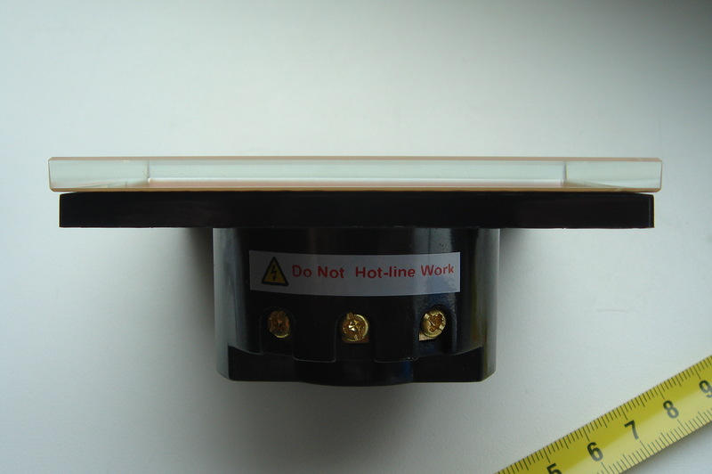
Radio sockets are the simplest ones (mine were bought in Leroy Merlin, under their own brand). There are a lot of different names, but the essence is the same: usually there are three sockets and a remote (for some reason, four sockets). On the back of the sockets - the switch that selects the channel. If you put everything on one, then they will turn on with one button on the remote, which is suitable for organizing groups. Moreover, the on and off commands are different, so a pair of buttons is responsible for one channel-group. This is convenient - there is no feedback, so if you have any doubts, you can simply repeat the command to turn on (turn off) and it will come exactly from the tenth time. The operating frequency is 433 MHz.
. This, I hope, the last time I will look at the outlet, I will no longer

Maximum switching power is about a kilowatt. I use them to control the background light and turn the tablet on and off in the kitchen.
.

The second number is the two-button Livolo radio switches (there are other options, but I promised about my configuration). I bought them as the blond mentioned above. I saw everything — mi-mi-mi and want-not-I can. Fell in love at first sight. Also, as it turned out, 433 MHz and also no feedback.
.

The advantages of the switches are that they look perfect (for my taste) and are extremely simple (even with my radius of the curvature of the hands) mounted. Even better, they are oriented to a two-wire connection system and do not require additional power, therefore they are organically replaced by conventional key switches. I Livolo work with energy-saving lamps, and with LED (12V with a transformer and 220V) - neither they nor the others flicker in the off state.
. standard round box. For aesthetes come in square UK-performance
The minus, however, is that the same command is used to turn it on and off. Therefore, in the absence of feedback and in the event of interference or some kind of failures, it is impossible to unambiguously turn off or turn on any switch. The situation, however, is saved by a full-time command of switching off all the switches attached to a particular console at the same time (which I use when turning off electrical appliances and lights when I go out of the house).
As a result, I have one carrier frequency on my hands and two identical in essence but different in performance and, as a result, incompatible radio protocol. One is for light switches, the other is for radio sockets and sensors. Here is the last and put forward for discussion by the team in the first place.
Sockets though, I repeat, are simple to ugliness, but rather effective. Inside is a simple voltage converter, a simple (exactly the same as you buy for the Arduino) receiver, a chip decoder and a relay. In the remote - coding chip and transmitter. The peculiarity of the protocol is that it implies repeated repetition of the same code message (unique device number) while the remote control button is pressed or while the device (for example, the door sensor) is in the active state.
. not very rich but functional inner world of the outlet

This scheme is extremely widespread in all sorts of alarms and actuators, and is implemented on several of the most common chips.Usually they are searched for by the names SC2260 / SC2262 or PT2260 / 2262, and for Arduino there is the RC-Switch library , which handles all such compatible chips without any problems.
I will repeat quikstart. In general, it is possible to identify the “simple” periphery, for example, by remote control units. Usually this is a key ring with four (plus or minus) buttons. Often the maximum number of buttons is 8. But these are all indirect signs, since there is no guarantee that what will be inside is a compatible chip. The RC-Switch library used in the controller is compatible with the following chips: SC5262 / SC5272, HX2262 / HX2272, PT2262 / PT2272, EV1527, RT1527, FP1527 and HS1527. You can navigate in the search for these names.
.SC2262 in its remote. As required

I suppose that when this information settled down in my head, an insight happened. I then did three things: I connected the receiver to the Arduino, downloaded the sample code receiver, and pressed the home wireless button. Then he looked at the laptop screen and scored something on the topic of wireless sensors in the search for Aliexpress. And I felt like in a toy store, honestly.
Imagine: I realized that I could receive notifications that someone had pressed the call button, and I can connect a lot of different sensors, and without any trouble at all. Because these sensors are completely autonomous, they work on a single battery for a very long time and do not require any wires at all.
I had to put together a bunch of eyes, curb the desires and order what was really necessary (archival links as a starting point):
1) Smoke detectors - 3 pcs.
2) Leakage sensors - 3 pcs.
3) Door sensors - 2 pcs.
4) Motion sensor - 1 pc.
You can not make my mistake, and do not order a motion sensor. I will explain.This thing is effective only in security systems (where active movement is a sign of anxiety, and not ordinary life), and in a smart home a wireless motion sensor will only interfere. This is because it “screams” every time it is triggered, and thus, firstly, the controller distracts, and, secondly, it interferes with other sensors.
Obviously, there will be plenty of such “abstract moments” for the normal operation of the controller, because it is no secret that people tend to go around the house. And there is no time for the regular ability to remotely turn off this sensor.
Another controversial thing is the leakage sensor. Structurally, it consists of two parts - the transmitting unit and, in fact, the humidity sensor connected by a long wire and representing a pair of conductive tracks located at a short distance from each other. Ideally, this is a long wire and tracks.
In fact, you can get a wire with a length of 20 centimeters, and instead of a board with tracks, there is a box, inside of which a stripped stub of the same wire is fixed with hot glue. On the one hand, there is no fundamental difference, since everything works. And on the other hand, it is inconvenient to fix this, and even until this box is filled with water (or something else comes up), Borjomi will be late in drinking.
.inside my leak sensors and door chip CS5211AGP, which is not mentioned in the RC-Switch compatibility list, but works with it. This is for you to understand how popular the protocol is.

Another variant of Chinese creativity is to push the tank overflow sensor under the “water sensor”. There instead of the tracks - the body with a float. There is a reed switch in the case, a magnet in the float. Further, I suppose, no need to explain. For the registration of leaks, this thing is absolutely not suitable.
Hence the conclusion: signs of a racially correct leakage sensor - a long wire to the humidity sensor and a sensor that looks like a board with two etched tracks located at a short distance from each other.
.racially correct leakage sensor, next to it - door sensor

Smoke detectors I placed in the kitchen, in the hallway and in the room. Leakage sensors - under the sink in the kitchen, in the sanitary box in the bathroom and under the washing machine.
.smoke sensor on site

Door sensors used on the doors of the wardrobe and bathroom to control the light. Now, however, the sensor in the bathroom is not needed - the dedicated controller steers the light there.
.door sensor in place. His native antenna tore off during an antenna tantrum. Now there is a piece of wire completely arbitrary length. However, it works. Therefore, do not touch. This sensor is mounted on the end of the shelf in the wardrobe. And passing by sliding door, which is attached to a magnet.

Completing the list of peripherals are three buttons and a webcam.
1) Wireless call button (433 MHz) for notifications about callers at the door.
2) Wireless button "panic" from the alarm (it is used to control the feeder cats).
.This is the “panic”

3) Presence button for switching between security and light modes when leaving and returning home. In general, it is similar to the "panic" button, but I redid it from the bell button (I bought 315 MHz without looking) and the Chinese keychain. Actually, I bought the call button because it was attractive in appearance and comfortable - a large soft key. The alteration of the mention itself is not worth it - it is better to buy a finished one (call or panic).
.I'm at home. Prettier panic anyway

The principle of operation of wireless sensors is as follows:
1) The smoke sensor emits a beep and continuously sends a signal over the radio while the smoke threshold is exceeded. To be honest, I didn’t conduct any field tests - I used the test button. Yells strongly.
2) The door sensor transmits its signal within two seconds after triggering.
3) The leak sensor transmits its signal all the time that the humidity threshold is exceeded. How dry - silenced.
Autonomy sensors decent. Since the purchase in June last year, the batteries had to be changed only in the door sensors - but they also open more than once a day.
4) Buttons transmit a signal while pressed.
Actually the signal itself is a unique code message with a length of 24 bits. Usually it can be changed at will: there are either usual jumpers on the board, or platforms that can be bridged with solder. The package is monolithic on the air, but structurally consists of two parts: the device address and the unique number. The address is usually used in the alarm system, which allows the sensors to be logically combined into security zones.
I don’t need these zones, so I consider the whole package to be a unique number and I’m following only to make these numbers truly unique. That is, so that they do not repeat among my periphery, and that the neighbors do not have similar ones (this can be calculated from false positives, which, however, I have not had).
It is this code message that is used by the central controller to identify the activated sensor. Sometimes the address and number are written on the body of the sensor. But personally, I learned the numeric names of the sensors using the Arduino, the receiver and the RC-Switch library. You just need to connect the receiver to the controller (by default, the DATA receiver to 2 digital pin) and load the ReceiveDemo example from the RC-Switch folder.
Then, in turn, activate the sensors and record someone's name. We do not throw out the leaflet - it is useful when adapting the code of the central controller.
I used the implementation of this protocol in RC-Switch for other things as well: I use invented unique numbers as commands and data transport for service controllers. For example, the central controller says 012345678, and the service controller receives this code and knows that it needs to send a command to turn on the TV. Or, for example, the meteorological sensor issues a trill of the form 1281265739, and the central controller knows that 1281 is the name of the room sensor, 265 is the temperature (only divided by 10), and 739 is the atmospheric pressure.
That is quite a two-way protocol, albeit at low speed and without error correction.
With switches Livolo almost the same, but not quite. The code message is still divided into two parts, but the first is the unique identifier of the remote control, and the second is the code of the button pressed on the remote. Since the switches are trainees, it doesn’t matter what the remote control ID is (they will be remembered when they met), and the key codes are formed according to a very simple rule.
What do we end up with? If there is a remote control and you want to use it with the central controller, then you need to find out the unique identifier of the remote control. And here this code will help us . Everything is the same as RC-Switch: we connect the receiver, load the code, click on the button of the remote and record the identifier and the code of the button. Repeat with all the buttons that we are going to use.
If there is no remote control, and there is no need for it either, then simply a library to manage Livolo is sufficient . Included with it - a description of the use and example, as well as the codes of a number of buttons. Thus, you can make a completely arbitrary number of remotes and, I suspect, an arbitrary number of buttons, if you follow the rules (16 bits - the remote control ID, 7 bits - the button code).
I will try to tell about how this library appeared in a separate text. And for the most inquisitive minds I inform you that although “virtual” consoles do work, for some reason, not all 16-bit console identifiers are suitable.
Finally, a webcam. I have a simple and long-bought D-Link DCS-930. It has no features, except that the angle of view of the lens is increased with a wide-angle attachment ( fisheye ) for a mobile phone.
At first, I used the usual segments of breadth-up wires 173 mm long - as quarter-wavelengths - as an antenna. And until a certain point, it worked, but with an increase in the number of wireless peripherals, miracles began to happen. The periphery either worked or did not work.
It was obvious that the problem was either in the code or in the transmit-receive part. I checked the code and could not find any errors. So, it's in the radio channel. Reading the texts dedicated to the range and types of 433 MHz antennas did not make me happy: it turned out that the connection at this frequency is quite capricious, and the waves tend to be great to reflect from the nearest surfaces and stack up to self-destruct.
At the same time, I found out that I may not have chosen the length very well. One comrade in the DIY forum recommended using an “electric” conductor length, which he estimated to be on average 0.95 of the calculated one. That is, if 1/4 wave of 433 MHz = 173 mm, then the electrical length is 165 mm. I immediately redid the antennas, but did not notice any special efficiency.
In the next step, I decided to try spiral antennas. They were said about them that they are much less capricious than the pin ones (a piece of wire is the essence of the pin pin in a disgusting performance), although a little less effective. In the spiral, I twisted the same 165 mm lengths, but already the first wire that came under the arm, which could be twisted, that is, a classic electrical cable with a cross section of 1.5 mm2.
.when my antenna (in the center) twisted

Amazingly, these things were already much more stable and better. But still not very much, and aesthetics, again. So in the end, I ordered a bundle of prefabricated spiral antennas on Ebay.
.and this is the factory. Although we all know which plants are in China.

In general, they solved my problems, although miracles did not happen. It is also interesting that regardless of which antennas I used in the controller, additional service controllers and self-made peripherals, the factory wireless sensors and switches worked more stable.
Therefore, a summary: good antennas and transmitters are very important, as well as, if possible, a well thought-out arrangement of the central controller relative to the periphery.
The second summary: if something goes wrong, it is possible that the point is not in the code, but in the radio channel.
At the time of the assembly, I did not have a real time clock, but I wanted to switch Avtosvet modes depending on the time of day. And when the clock appeared, there was no place for the library for them. Therefore, I used the obvious (for myself) solution - Tasker , who settled in a smartphone long ago.
The ideology is simple.
1) I deliver profiles in a context where the required time interval is indicated.
2) For each profile I add the necessary tasks (Task) with actions from the category Net (Net) - HTTP Post.
3) In the address bar for each POST request, I indicate the address of the controller, including the command to be executed. For example: 192.168.10.48/?Switch1-on
The scenario is obtained if you collect several actions in one task. In other words, part of the logic is taken out of the controller, which gives very tangible advantages:
1) Implement scenarios without consuming controller resources
2) Elementary adding new scripts
3) Easy and quick change settings
4) Always accurate time.
Cons, too. If Android with logic on board is discharged or freezes (or the network disappears), the script will not be executed.
With this solution, I switch day and night automatic light modes. That is, “Avtosvet Day” = turning on the automatic light in the hallway, allowing music in the bathroom and turning off the automatic light in the kitchen. And “Avtosvet night” is the opposite action.
In addition, I simply pulled out some useful (for me) controller functions in the form of task shortcuts to one of the smartphone screens. So just one click is enough, like on a regular touch button. And no long URLs in the browser.
In the end, this “logic” moved from a smartphone to an Android keychain connected to a TV. So for the network you can worry less, and for food.
Now I will go through the code and try to describe at least the basic algorithms of the controller so that it becomes a little clearer what I had in mind.
Successful activation of the controller confirms a short double beep. This means that the controller has switched to standby mode. At the same time, the “System started” notification is sent to the mail service address.
When enabled, the following basic parameters are set:
- “I am at home” - the truth
- Avtosvet in the hallway - off
- Avtosvet in the kitchen - off
- Avtosvet in the bathroom - included
- Time of rotation of the feeder sector - 15 seconds
- Webcam - off
- Status of smoke and leakage sensors - no alarm
- Music in the bathroom - off, allowed
- Motion sensor in the hallway - included
- Debug mode for motion sensor - off
With an interval of two minutes, the controller checks for the Internet: it connects to Yandex. If you connect - there will be nothing. And if not, the router is restarted by turning it off and on.
A total of two reboots are performed in a row. If after that the Internet did not appear - timeout per hour. Then check again.
The second periodic action is sending the weather to the Internet at one hour intervals for the service " People's Monitoring ". Uses HTTP protocol, POST method. To use this function, you will need an account on the service website.
The readings of any of the sensors are sent, provided that the sensors have transmitted all the parameters that can be transmitted. If the sensor has not transmitted one of the parameters, it is considered that there is no indication (sensor failure).
If the readings are transmitted by both sensors, both sets are transmitted to the Internet simultaneously.
The data from the meteorological sensors are transmitted to the controller via radio using a primitive RC-Switch based protocol:
1) Room sensor transmits the numbers of the form:
a) Pressure: 1210XXXX, where XXXX is the atmospheric pressure in hPa up to integer.
b) Temperature: 1310SXXX, where S is 1 (below zero) or 0 (above zero) depending on the sign of the temperature, and XXX is the temperature with an accuracy of tenths multiplied by 10.
2) The outdoor sensor transmits the numbers of the form 161HSXXX, where H is a sign of humidity, S is a sign of temperature, XXX is a value of a climatic parameter with an accuracy of tenths multiplied by 10.
If H = 1, the controller considers that the moisture readings are transmitted. If H = 0, the controller thinks it got a temperature.
Both parameters are transmitted by each meteorological sensor with a small interval.
A ready POST request for two sensors looks like this:
Here MAC00 is the logical address of the head unit, MAC01 is the logical address of the temperature sensor, MAC02 is the logical address of the pressure sensor. In this case, physically, temperature sensors can be one or different devices. For example, my home sensor uses the BMP085 sensor, which simultaneously measures temperature and atmospheric pressure. In this case, it is assigned two addresses (MAC01 and MAC02), and the address of the head unit is a thing, in general, not tied to anything. This is simply the address of a certain virtual owner of individual sensors.
If the sensor is turned off, no action is taken. Otherwise, the following actions are performed.
1) If the automatic light control is turned off and if someone is at home, the sensor does not perform any functions.
2) If Avtosvet is turned on in the hallway, a single pass causes the light to turn on in the hallway for 1 minute. Repeated passage during this minute extends the time of light work up to 3 minutes. Each subsequent pass likewise extends the time of light up to three minutes. If the movement is not recorded for three minutes, the light turns off.
3) If Avtosvet is turned on in the kitchen, the passage causes the light to turn on in the kitchen for 10 minutes. Each repeated pass does not change the time of the light, but leads to the issuance of a command to turn it on. The reason is that sometimes the light in the kitchen does not turn on at the first attempt (radio channel or controller occupancy). Then, if it is clear from the corridor that the light did not turn on, it is enough to take a step back - under the sensor.
4) In the absence of people at home, triggering the sensor results in an email notification of the event.
5) When the motion sensor debug mode is on, each recorded movement is confirmed by an audible signal. If Avosvet in the kitchen is turned on at the same time, in addition, each time the sensor is triggered, the kitchen light turns on for 30 seconds. This is for more visual debugging and at the same time it was for debugging Avtosvet in the kitchen.
Each door opening will issue a command to the light switch. Each such command turns the light on or off, depending on the state in which it was before issuing the command.
The peculiarity of the algorithm is that the light is switched on with a delay of 1.7 seconds. This is necessary because the sensor “screams” for about 2 seconds, and if you issue a command to turn on the light immediately, the controller may have time to “catch” the end of the sensor's trill, and once again switch the light. The delay does not create much discomfort, but it prevents the lights from turning off immediately after switching on.
A similar algorithm works in the case of using Avtosvet by the door sensor in the bathroom.
Pressing the button when leaving home leads to the following scenario:
1) 1 minute pause
2) Turn off all radio sockets
3) Turn off all radio light switches
4) Disable avtosveta in the hallway, if it was turned on
5) Turn off the music in the bathroom
6) Switching the motion sensor to the protection mode with notification of mailings
7) Turn on webcam with email notification
Pressing the button on returning home runs another script:
1) Turn off the webcam with email notification
2) Turn on the background light in the room
3) Turning the background light on the kitchen
4) Enable avtosveta in the hallway, if it was turned on before leaving; or turning on the light in the hallway if the auto light in the hallway was turned off at the time of leaving the house
The button works on the principle of a trigger: each press switches the mode to the opposite (home-not home).
The feeder (modified from conventional Feed-Ex) is a bowl with four compartment-sections, closed with a lid. The cut in the lid allows access to only one sector. Sectors are filled with food through one. Thus, each turn on the sector or opens the feed, or stops access to it.
. feeder in original condition

This is not a slaughter, but an urgent need, since one cat needs to be kept on a diet, and you should not leave feed in access all the time.
. filling principle

When you click on the "Feeder" button, the feeder turns to one sector (by timer) and the delay in this state is 2.5 minutes so that the cats have time to walk and eat.
After 2.5 minutes, the feeder turns further into the sector (empty). Thus, feeding is stopped.
If the button is pressed again before the expiration of the 2.5-minute interval, an immediate sector rotation (closing) is performed, and the timer rotation is canceled. This is an emergency closure procedure, if someone is close to the trough and sees that a cat not authorized for this operation has been attached to it.
When the sensor is triggered, a command is issued to switch the light and turn on the music, if the inclusion of music is allowed. When the sensor is triggered again, a command is issued to switch the light on and to turn off the music.
If during the operation of the light and music, the controller receives a command to ban music in the bathroom, the music is turned off.
1) When a smoke sensor is triggered, the controller notifies by mail a letter indicating the location of the sensor
2) When a leakage sensor is triggered, the controller notifies by mail with a letter indicating the location of the sensor, 10 beeps are simultaneously emitted with an interval of 10 seconds, since leakage sensors do not have an audible notification function
3) The operation of any sensor is considered a critical event, after which the reception of signals from sensors is blocked until the state of the sensors is reset via the web interface.
The reason for blocking is that when triggered, the sensors transmit a signal continuously. This means that the controller (without blocking) will respond to it as soon as it is freed from the previous mail notification. I don’t see much sense in this, therefore - blocking until manual reset.
The controller transmits using the RC-Switch library a numeric command for the media controller. About media controller - in future releases :)
In the absence of a park of pigeons in specially equipped cells with electromechanical locks, everyone has a clear desire to use the simple and quite convenient SMTP protocol for sending letters. However, many mail services have switched to SSL authentication, while the Arduino simply does not have the strength to do so.
Decision? We make a compromise with security, we search and exploit a mail server capable of open authorization. That is why I use Mail.Ru - it meets the requirements.
I know perfectly well the shortcomings of the current implementation - it just stops all activity at the time of sending the letter due to the delay delays necessary to guarantee the wait for the server response. An interactive scheme with reading the lines received from the server would be a little faster, but I didn’t immediately manage to “start” it. But this algorithm, picked up on the forums Arduino.cc , earned immediately.
For this reason, by the way, a motion sensor is notified with a 30-second delay. This is done in order to have time to press the "I am at home" button when returning. If this delay is not present - at the entrance a letter is immediately sent, and the controller stops responding to external stimuli for about ten seconds.
As a result, for mail notifications you will need:
1) Mail.Ru Mailbox
2) Login encoded in BASE64
3) Password encoded BASE64
In order to encode your username and password, you can use one of the many (thousands of them) online services.
The page at the controller's address displays the last significant state (according to the list of status lines in the sketch), as well as the latest meteorological data obtained.
Well what can I say? Watch and tremble, because the spectacle is as fascinating as I think it’s terrible - from the point of view of any more or less adequate programmer.
Functions, variables, etc., etc., were added as needed, which explains the absolute nonlinearity of the code. Nevertheless, I tried to comment in as much detail as possible on almost everything I did. First of all - for yourself. Because after a week I already forget what, why, and why it is so, and not otherwise.
For the sketch to work correctly, several non-standard libraries are required. Do not forget to copy them into the libraries folder of your Arduino environment directory:
1) RC-Switch for controlling sockets, radio relay and exchange with meteorological and service sensors.
2) Livolo to control light switches of the same name.
3) SimpleTimer for counting time intervals.
Adapting the code, if I'm not confusing anything, includes the following changes:
1) Pin definitions. If you want to connect the periphery of the Arduino in a different way, you will have to change it, and if you connect it as in the code, you don’t need to touch it. For convenience, the pins are defined in the variable section, the rest of the code is not necessary.
2) Network settings.
3) Mail parameters (sendMail procedure).
4) Section of the wireless sensor signal handler. Here it is necessary to replace the sensor numbers with your own.
5) Peripheral commands in the code. They can be found by the name of the txSwitch “transmitter” procedure (this is for sockets, radio relay and service controllers) and by the name of the livolo library function (for light switches).
6) Section of parameters of weather and climate data for the service " People's Monitoring ".
7) Section for processing web-interface commands. Here you can change the names of the teams to those that you like best. And you can not change.
Critical points: 2 - 6. If you do not configure the network and mail (for mail you will still need an account on the mail service with SMPT and open authorization) - there will be no remote control and notifications by mail. If you do not change the sensor identifiers to yours - the controller will not “hear” them. And if you don’t change the outlet commands, you won’t be able to control them. For Livolo, however, the correction of codes is not vital, because if you put the switch in the learning mode, it will pick up the command on the fly.
Similarly, if you want to broadcast the weather to the Internet, you need to register on the website of the “People's Monitoring” to drive the MAC of your head unit (controller) and sensors. Addresses can be taken arbitrary. Take, for example, an old network card or any other network device, look for a MAC sticker and take it as the address of the head unit. And then change the last (or some like) digits to get the required number of addresses. For the current code, all you need is five addresses: a head unit and four sensors (each parameter is considered a sensor, and there are four of them: inside and outside temperature, pressure and humidity).
The core of the sketch is a web server with a web interface command handler and a signal handler from wireless sensors. Everything else is a bit of a peripheral strapping.
Last: I tried not to spoil anything when depersonalized. But if you spoiled - I apologize, and we will understand together.
Functionality increased gradually: first I connected the wireless sockets, then swung at the light switches. Appetites grew - leaking sensors, smoke, doors, weather sensors, radio relay and control AV-technology. Mastery did not grow so fast. Therefore, it turned out what happened: a thing infinitely far from the guidelines on programming and electronic circuits, but quite workable.
And you know what? It suits me.
')
Other devices and devices of the series
If you suddenly missed the content of the first series, just in case I remind you . This text will not be as incendiary, since more instructions. In addition, at the very beginning I am planning a large-scale "disclaimer of warranties". The fact is that I am extremely far from both circuitry and programming. Therefore, what I did turned out exactly as it happened (I wanted to use even more, but it did not work).
I, of course, will try to answer the questions "why so and not so?", But in many cases it will look like if you asked the blonde why she turned on the right turn signal and left the rightmost row of her strip to the extreme right row counter. Practically everything that now exists acts on the fundamental principle “Does it work? Do not touch!".
For the same reason, I will show the code and scheme in the original configuration with the minimum possible changes (mainly anonymization of personal data). It should, with a high degree of probability, allow it to be repeated in working condition. And then you can comb and decorate everything as you like. Unless, of course, want to repeat.
Please understand that I have not reached the modification of Arduino to download sketches through a local network. And any modification of the code turns around running around with stools and a headache with the return to working condition of the motion sensor. Therefore, I will a priori be hostile to perceive even worthwhile sentences. Most likely, then I will chill and not only take note, but also implement your advice.
Therefore, I apologize in advance for possible violent reaction.
FAST START
Control of wireless executive devices using amplitude modulation of carrier frequency and protocol and / or SC2260 / SC2262 or similar encoder chips, and similar, as well as Livolo wireless light switches .
It can be all kinds of radio relay, wireless sockets, wireless switches, LED strips with remote control, home alarms and in general everything that China lacks chips and imagination. Such peripherals are usually performed in two frequency solutions: 433 MHz or 315 MHz. In principle, you can choose any, but in Russia, it seems, 433 MHz is officially allowed, although at 315 MHz, no one is likely to be broadcasting ten meters.
You may already have some of these devices, but if not, the technology is such that they are very accessible, unlike, say, Z-Wave, ZigBee, Xbee or X10 peripherals. Although these protocols are, of course, more reliable and secure.
It is possible to identify the “simple” periphery, for example, by remote controls. Usually this is a key ring with four (plus or minus) buttons. Often the maximum number of buttons is 8. But these are all indirect signs, since there is no guarantee that what will be inside is a compatible chip. The RC-Switch library used in the controller is compatible with the following chips: SC5262 / SC5272, HX2262 / HX2272, PT2262 / PT2272, EV1527, RT1527, FP1527 and HS1527. You can search for these names in the search.
As for the switches Livolo, then there is no diversity. Only they, because they invented their own protocol. If you order from them, please note - not all switches are wireless there.
First of all, the controller is designed to execute commands via the web interface using standard POST requests. The elementary type of request is simply to enter the address of the controller and the commands in the browser string. Anyone with the browser. Thus, the controller, and, therefore, devices “connected” to it can be controlled from almost any modern phone, tablet or computer — would be Internet access.
In the simplest case, the request looks like this: 192.168.10.48/?Switch1-On
Here "192.168.10.48" is the controller's address; "?" means that the next - the team; "Switch1-On" is a command.
Commands are hard coded in the controller code at the time of programming. You cannot change them on the fly. The command received via the web interface is compared by the controller with the existing list and, in case of coincidence, is executed. Otherwise, it is ignored.
The controller can also respond to commands from the control panels (with the chips mentioned above) and execute scripts or simply switch (in essence, the repeater function) the technician upon receiving their signals. Scenarios or commands are also rigidly described in the controller code at the time of programming.
To build the controller in the minimum configuration will require:
1) Arduino Uno
2) Ethernet Shield with Wiznet W5100 chip
3) Amplitude modulated signal receiver (ASK / OOK) 433 MHz (or peripheral frequencies). Something like this .
4) Amplitude Modulated Signal Transmitter (ASK / OOK) 433 MHz (or peripheral frequencies). Something like this .
5) DC 9V source with 5.5 / 2.1 mm jack (standard connector on the Arduino board)
6) Dummy
This is enough to control the periphery via the Internet and receive commands from the radio controls.
Assembly sequence:
1) Install Ethernet Shield on the Arduino board
2) Connect the transmitter: DATA to pin 8 Arduino; GND - to the power supply minus; VCC - to the plus power.
3) Connect the receiver: DATA to pin 2 Arduino; GND - to the power supply minus; VCC to 5V Arduino output.
Be careful: conventional ASK / OOK transmitters operate in the range from 3V to 12V, so you can connect them directly to a 9V power supply. At the same time, conventional ASK / OOK receivers are designed for 5V, so they must be connected either to the 5V output of the Arduino or to the stabilizer 5V.
The characteristics of the Arduino indicated that the optimum external power supply voltage is 7V - 12V. Therefore, in principle, you can use any of the power sources in this range if you don't have 9V at hand.
Before use, adapt the code for your peripherals. About this - at the end of this text, where, in fact, is the code. Do not forget about non-standard libraries.
For basic functions (wireless peripheral management), you will need:
1) Specify the parameters of your network in the code.
2) Enter the control codes of the peripheral devices in the code (download the example of the ReceiveDemo to the controller and press the buttons of the device’s remote control to find out; if you want to control the Livolo switches from both the remote control and the controller, use this code to find the remote control ID) .
Commands of ordinary peripherals in the code can be found by the name of the txSwitch () procedure. In brackets - the control code of the device. Livolo commands can be recognized by the name of the livolo.sendButton () procedure. The first number in parentheses is the remote control ID, the second is the button code (the button codes are indicated in the library description)
3) Rename web-interface commands as you like (interface commands can be found in the code by the name of the processCommand procedure.
4) To your taste, you can rewrite the status lines (you can find in the code by the comment "// status lines in PROGMEM" that will be displayed when executing commands. Note: to save memory, the lines are not specified for all commands.
5) I recommend commenting out the contents of the sendMail () procedure, if you do not plan to use email notifications. Otherwise, specify the postal address of the controller, the login and password of its account in BASE64 encoding, and the postal address of the notification recipient. I remind you that email notifications consist of status lines (Section 4).
After everything is ready, upload the code to the controller. Then connect the controller to the power supply and LAN. Now you can try to control it by typing the address of the controller and one of the commands that you set for the web interface.
In general, all this should allow the controller to start. Below is a description of the full configuration and configuration features.
Quickstart
Controller assignment
Control of wireless executive devices using amplitude modulation of carrier frequency and protocol and / or SC2260 / SC2262 or similar encoder chips, and similar, as well as Livolo wireless light switches .
It can be all kinds of radio relay, wireless sockets, wireless switches, LED strips with remote control, home alarms and in general everything that China lacks chips and imagination. Such peripherals are usually performed in two frequency solutions: 433 MHz or 315 MHz. In principle, you can choose any, but in Russia, it seems, 433 MHz is officially allowed, although at 315 MHz, no one is likely to be broadcasting ten meters.
You may already have some of these devices, but if not, the technology is such that they are very accessible, unlike, say, Z-Wave, ZigBee, Xbee or X10 peripherals. Although these protocols are, of course, more reliable and secure.
It is possible to identify the “simple” periphery, for example, by remote controls. Usually this is a key ring with four (plus or minus) buttons. Often the maximum number of buttons is 8. But these are all indirect signs, since there is no guarantee that what will be inside is a compatible chip. The RC-Switch library used in the controller is compatible with the following chips: SC5262 / SC5272, HX2262 / HX2272, PT2262 / PT2272, EV1527, RT1527, FP1527 and HS1527. You can search for these names in the search.
As for the switches Livolo, then there is no diversity. Only they, because they invented their own protocol. If you order from them, please note - not all switches are wireless there.
Management principle
First of all, the controller is designed to execute commands via the web interface using standard POST requests. The elementary type of request is simply to enter the address of the controller and the commands in the browser string. Anyone with the browser. Thus, the controller, and, therefore, devices “connected” to it can be controlled from almost any modern phone, tablet or computer — would be Internet access.
In the simplest case, the request looks like this: 192.168.10.48/?Switch1-On
Here "192.168.10.48" is the controller's address; "?" means that the next - the team; "Switch1-On" is a command.
Commands are hard coded in the controller code at the time of programming. You cannot change them on the fly. The command received via the web interface is compared by the controller with the existing list and, in case of coincidence, is executed. Otherwise, it is ignored.
The controller can also respond to commands from the control panels (with the chips mentioned above) and execute scripts or simply switch (in essence, the repeater function) the technician upon receiving their signals. Scenarios or commands are also rigidly described in the controller code at the time of programming.
Controller assembly
To build the controller in the minimum configuration will require:
1) Arduino Uno
2) Ethernet Shield with Wiznet W5100 chip
3) Amplitude modulated signal receiver (ASK / OOK) 433 MHz (or peripheral frequencies). Something like this .
4) Amplitude Modulated Signal Transmitter (ASK / OOK) 433 MHz (or peripheral frequencies). Something like this .
5) DC 9V source with 5.5 / 2.1 mm jack (standard connector on the Arduino board)
6) Dummy
This is enough to control the periphery via the Internet and receive commands from the radio controls.
Assembly sequence:
1) Install Ethernet Shield on the Arduino board
2) Connect the transmitter: DATA to pin 8 Arduino; GND - to the power supply minus; VCC - to the plus power.
3) Connect the receiver: DATA to pin 2 Arduino; GND - to the power supply minus; VCC to 5V Arduino output.
Be careful: conventional ASK / OOK transmitters operate in the range from 3V to 12V, so you can connect them directly to a 9V power supply. At the same time, conventional ASK / OOK receivers are designed for 5V, so they must be connected either to the 5V output of the Arduino or to the stabilizer 5V.
The characteristics of the Arduino indicated that the optimum external power supply voltage is 7V - 12V. Therefore, in principle, you can use any of the power sources in this range if you don't have 9V at hand.
Start of operation
Before use, adapt the code for your peripherals. About this - at the end of this text, where, in fact, is the code. Do not forget about non-standard libraries.
For basic functions (wireless peripheral management), you will need:
1) Specify the parameters of your network in the code.
2) Enter the control codes of the peripheral devices in the code (download the example of the ReceiveDemo to the controller and press the buttons of the device’s remote control to find out; if you want to control the Livolo switches from both the remote control and the controller, use this code to find the remote control ID) .
Commands of ordinary peripherals in the code can be found by the name of the txSwitch () procedure. In brackets - the control code of the device. Livolo commands can be recognized by the name of the livolo.sendButton () procedure. The first number in parentheses is the remote control ID, the second is the button code (the button codes are indicated in the library description)
3) Rename web-interface commands as you like (interface commands can be found in the code by the name of the processCommand procedure.
4) To your taste, you can rewrite the status lines (you can find in the code by the comment "// status lines in PROGMEM" that will be displayed when executing commands. Note: to save memory, the lines are not specified for all commands.
5) I recommend commenting out the contents of the sendMail () procedure, if you do not plan to use email notifications. Otherwise, specify the postal address of the controller, the login and password of its account in BASE64 encoding, and the postal address of the notification recipient. I remind you that email notifications consist of status lines (Section 4).
After everything is ready, upload the code to the controller. Then connect the controller to the power supply and LAN. Now you can try to control it by typing the address of the controller and one of the commands that you set for the web interface.
In general, all this should allow the controller to start. Below is a description of the full configuration and configuration features.
Functional
So, the central controller. To begin, I will repeat its functions:
1) Management of four radio sockets;
2) Control of 8 buttons of four radio light switches;
3) Reboot the router when the Internet is lost;
4) Turn on and off the webcam;
5) Monitoring 8 wireless sensors OPS (three smoke sensors, three leak sensors, a pair of door opening sensors);
6) Receive data from two meteorological sensors and transfer them to the Internet;
7) Control TV, media player and air conditioning;
8) Manage the cat feeder;
9) Monitoring the wired motion sensor;
10) Event notification by email.
Service functions (scripts):
1) Automatic control of light in the wardrobe;
2) Automatic control of the light in the hallway;
3) Automatic control of night lighting in the kitchen;
4) Automatic control of light and music in the bathroom (at the time of writing - two options: by the controller itself and the commands to the controller in the bathroom);
5) Turning off everything that turns off remotely, turning on the camera and switching the motion sensor to protection mode when leaving home; and turning off the camera with turning on the background light, the light in the hallway and switching the motion sensor to the previous one, before guarding, on return.
Why do I need two power supplies
Paradoxically, the central controller is connected directly to two network adapters, which is associated with different supply voltages of the webcam and router it controls.
In other words, block 9B feeds the controller, and its relay is switched to power the router, and block 5B is used to power the webcam and peripheral auxiliary power, because the Arduino lacks all the outputs and capabilities.
Already now I understand that one sufficiently powerful 9V block and one 5V stabilizer would be enough. And maybe later I'll come back to this. And you can immediately remove the extra piece of iron from the list.
By the way, curiously, I only now realized the whole tragic idiocy of the situation. Blonde, in short.
Glands
To prepare the controller you will need (links only for an example):
1) Arduino Uno - 1 pc.
2) Ethernet Shield with Wiznet W5100 chip - 1 pc.
3) ASK / OOK receiver 433 MHz - 1 pc.
4) 433 MHz ASK / OOK transmitter - 1 pc.
5) Motion sensor HC-SR501 - 1 pc.
6) Block (at least 2 pcs. In the block) 5V relay with keys - 1 pc.
7) Piezoceramic squeaker - 1 pc.
8) Power sources. At least - 5V for Arduino and its periphery. Better - 9V and stabilizer 5V for the periphery.
9) Antennas for receiver and transmitter, if they are not.
10) Dummy or other wires, connectors and housing to taste.
Basically, there are no problems with the selection of components. The most critical are the receiver, the transmitter ( usually sold in sets ) and their antennas. In my opinion, apart from the price, there is no particular difference between superregenerative and superheterodyne receivers (maybe I do not know how to prepare them).
. conventional transmitter. The inscription in defocus reads FS1000A
True, I liked the transmitter, bought on the occasion of the DX . He, in addition to being more expensive than others, is already equipped with a spiral antenna and subjectively works better than very cheap transmitters, which I tried to equip with home-made and spiral "factory" antennas .
. the usual superregenerative receiver, to which I have already managed to solder the “antenna”
But the superheterodyne receiver bought in the same place, as I said above, was not impressed.
To the question of antennas, by the way, I'll be back - I had a very sore point. In the meantime, let me remind you that cheap receiver and transmitter kits are sold without antennas. And this does not mean that it should be so. This means that you will have to either make the antennas yourself, or buy ready-made ones.
Piezoceramic tweeter got this place because it does not need additional components. Internal resistance allows you to connect directly to the Arduino. And it also screams quite loudly and is very compact.
And in order not to get up two times: Arduino Uno because I chose the first controller. For the same reason - network shild with W5100. After all, judging by the then opinion, these were the best things for beginners. I did not know that everything would go so far.
. Shield does not interfere at all to assemble a prototype
The purpose of the components is quite transparent. Ethernet-Shield provides the web server on the Arduino and, accordingly, remote management, configuration and status monitoring. The receiver listens to the sensors, the transmitter sends controller commands to the actuators (sockets, switches) and service controllers.
A motion sensor attached to the controller is used for security modes and automatic light control. A squeaker informs about successful activation, reception of some radio commands (for example, confirms that it heard the power button on the feeder so as not to press it until complete and final satisfaction) and is used to set up the same motion sensor (the warning when the sensor is triggered helps to set the direction sensitivity and identify false positives).
The relays turn on and off the router and the webcam, which is very important if you consider that my router is hidden not only out of sight, but also at a height higher than my height. The result is a reboot of the network without problems and the physical shutdown of the camera when it is not in use, which gives some psychological comfort.
. convenient relay unit with direct connection to the Arduino. It is simply impossible to connect the relay - the current consumed by the coil is too large. And here on the board optocoupler and a transistor switch plus a status LED
The controller assembly is nothing extraordinary. Only, of course, do not forget to fasten the Ethernet shield on the Arduino Uno right away and remember that the network shield uses the 4, 10, 11, 12 and 13 Arduino Uno pins, so they are not used in the controller functions. Fortunately, Uno has enough digital pins and a full set of analog ones.
The current configuration is reflected in the sketch and, just in case, here.
A0 - DATA Motion Sensor
2 - DATA Receiver
5 - to the control input of the router's relay block
6 - to the control input of the camera relay unit
8 - DATA Transmitter
9 - to plus tweeters
All GND (ground) of all components and all VCC (pluses) are connected accordingly. Those. the land is common for everyone, and if the supply voltage is different, each component should receive its own.
For simplicity and extensibility, I soldered several (four, maybe) pieces of a prototype wire with “mothers” to the 5V connector, so that, if anything, we quickly connected new components to the power supply. And it turned out, as usual with me - foolishly. I did not immediately unsolder, but when I realized that the Arduino power pins were not enough.
Another important feature is the connection of peripheral devices to the relay. I connected the camera to the normally open contacts, and the router to the normally closed. So, in the initial state of the system, the router is always on, and the camera is off. But I have a suspicion that I did not think of anything here, because I forgot to check what happens when the controller loses power. Just keep in mind this feature.
. it should end up with something like this. And this, apparently, KCD-V-1-1 (the first hardware and software version of the controller). For simplicity, the receiver is wrapped in black duct tape - but what is it that?
For reference: the cost of the first version of the controller, including the case and connectors, was about $ 60. It was already later that I went into the dressing and began to experiment with the ultrasonic sensor and, in desperation, bought a bunch of receivers, transmitters and antennas, in order to finally solve the problems of the unsteady reception and transmission of signals.
Already all gathered? Congratulations! Now is the time to double-check the connection of the signal wires and three times the power supply. Words cannot convey how many times I have been mistaken in routine operations, especially if during the re-assembly I had to change the connection of components several times. I do not want the same thing to happen to you.
Periphery
The current composition of peripheral devices and interaction with them is a chain of random coincidences and, in general, history. Since I first bought radio receptacles and switches, I first danced from them, and then to new performers, taking into account what has already happened.
Radio sockets are the simplest ones (mine were bought in Leroy Merlin, under their own brand). There are a lot of different names, but the essence is the same: usually there are three sockets and a remote (for some reason, four sockets). On the back of the sockets - the switch that selects the channel. If you put everything on one, then they will turn on with one button on the remote, which is suitable for organizing groups. Moreover, the on and off commands are different, so a pair of buttons is responsible for one channel-group. This is convenient - there is no feedback, so if you have any doubts, you can simply repeat the command to turn on (turn off) and it will come exactly from the tenth time. The operating frequency is 433 MHz.
. This, I hope, the last time I will look at the outlet, I will no longer
Maximum switching power is about a kilowatt. I use them to control the background light and turn the tablet on and off in the kitchen.
.
The second number is the two-button Livolo radio switches (there are other options, but I promised about my configuration). I bought them as the blond mentioned above. I saw everything — mi-mi-mi and want-not-I can. Fell in love at first sight. Also, as it turned out, 433 MHz and also no feedback.
.
The advantages of the switches are that they look perfect (for my taste) and are extremely simple (even with my radius of the curvature of the hands) mounted. Even better, they are oriented to a two-wire connection system and do not require additional power, therefore they are organically replaced by conventional key switches. I Livolo work with energy-saving lamps, and with LED (12V with a transformer and 220V) - neither they nor the others flicker in the off state.
. standard round box. For aesthetes come in square UK-performance
The minus, however, is that the same command is used to turn it on and off. Therefore, in the absence of feedback and in the event of interference or some kind of failures, it is impossible to unambiguously turn off or turn on any switch. The situation, however, is saved by a full-time command of switching off all the switches attached to a particular console at the same time (which I use when turning off electrical appliances and lights when I go out of the house).
As a result, I have one carrier frequency on my hands and two identical in essence but different in performance and, as a result, incompatible radio protocol. One is for light switches, the other is for radio sockets and sensors. Here is the last and put forward for discussion by the team in the first place.
Sockets though, I repeat, are simple to ugliness, but rather effective. Inside is a simple voltage converter, a simple (exactly the same as you buy for the Arduino) receiver, a chip decoder and a relay. In the remote - coding chip and transmitter. The peculiarity of the protocol is that it implies repeated repetition of the same code message (unique device number) while the remote control button is pressed or while the device (for example, the door sensor) is in the active state.
. not very rich but functional inner world of the outlet
This scheme is extremely widespread in all sorts of alarms and actuators, and is implemented on several of the most common chips.Usually they are searched for by the names SC2260 / SC2262 or PT2260 / 2262, and for Arduino there is the RC-Switch library , which handles all such compatible chips without any problems.
I will repeat quikstart. In general, it is possible to identify the “simple” periphery, for example, by remote control units. Usually this is a key ring with four (plus or minus) buttons. Often the maximum number of buttons is 8. But these are all indirect signs, since there is no guarantee that what will be inside is a compatible chip. The RC-Switch library used in the controller is compatible with the following chips: SC5262 / SC5272, HX2262 / HX2272, PT2262 / PT2272, EV1527, RT1527, FP1527 and HS1527. You can navigate in the search for these names.
.SC2262 in its remote. As required
I suppose that when this information settled down in my head, an insight happened. I then did three things: I connected the receiver to the Arduino, downloaded the sample code receiver, and pressed the home wireless button. Then he looked at the laptop screen and scored something on the topic of wireless sensors in the search for Aliexpress. And I felt like in a toy store, honestly.
Imagine: I realized that I could receive notifications that someone had pressed the call button, and I can connect a lot of different sensors, and without any trouble at all. Because these sensors are completely autonomous, they work on a single battery for a very long time and do not require any wires at all.
I had to put together a bunch of eyes, curb the desires and order what was really necessary (archival links as a starting point):
1) Smoke detectors - 3 pcs.
2) Leakage sensors - 3 pcs.
3) Door sensors - 2 pcs.
4) Motion sensor - 1 pc.
You can not make my mistake, and do not order a motion sensor. I will explain.This thing is effective only in security systems (where active movement is a sign of anxiety, and not ordinary life), and in a smart home a wireless motion sensor will only interfere. This is because it “screams” every time it is triggered, and thus, firstly, the controller distracts, and, secondly, it interferes with other sensors.
Obviously, there will be plenty of such “abstract moments” for the normal operation of the controller, because it is no secret that people tend to go around the house. And there is no time for the regular ability to remotely turn off this sensor.
Another controversial thing is the leakage sensor. Structurally, it consists of two parts - the transmitting unit and, in fact, the humidity sensor connected by a long wire and representing a pair of conductive tracks located at a short distance from each other. Ideally, this is a long wire and tracks.
In fact, you can get a wire with a length of 20 centimeters, and instead of a board with tracks, there is a box, inside of which a stripped stub of the same wire is fixed with hot glue. On the one hand, there is no fundamental difference, since everything works. And on the other hand, it is inconvenient to fix this, and even until this box is filled with water (or something else comes up), Borjomi will be late in drinking.
.inside my leak sensors and door chip CS5211AGP, which is not mentioned in the RC-Switch compatibility list, but works with it. This is for you to understand how popular the protocol is.
Another variant of Chinese creativity is to push the tank overflow sensor under the “water sensor”. There instead of the tracks - the body with a float. There is a reed switch in the case, a magnet in the float. Further, I suppose, no need to explain. For the registration of leaks, this thing is absolutely not suitable.
Hence the conclusion: signs of a racially correct leakage sensor - a long wire to the humidity sensor and a sensor that looks like a board with two etched tracks located at a short distance from each other.
.racially correct leakage sensor, next to it - door sensor
Smoke detectors I placed in the kitchen, in the hallway and in the room. Leakage sensors - under the sink in the kitchen, in the sanitary box in the bathroom and under the washing machine.
.smoke sensor on site
Door sensors used on the doors of the wardrobe and bathroom to control the light. Now, however, the sensor in the bathroom is not needed - the dedicated controller steers the light there.
.door sensor in place. His native antenna tore off during an antenna tantrum. Now there is a piece of wire completely arbitrary length. However, it works. Therefore, do not touch. This sensor is mounted on the end of the shelf in the wardrobe. And passing by sliding door, which is attached to a magnet.
Completing the list of peripherals are three buttons and a webcam.
1) Wireless call button (433 MHz) for notifications about callers at the door.
2) Wireless button "panic" from the alarm (it is used to control the feeder cats).
.This is the “panic”
3) Presence button for switching between security and light modes when leaving and returning home. In general, it is similar to the "panic" button, but I redid it from the bell button (I bought 315 MHz without looking) and the Chinese keychain. Actually, I bought the call button because it was attractive in appearance and comfortable - a large soft key. The alteration of the mention itself is not worth it - it is better to buy a finished one (call or panic).
.I'm at home. Prettier panic anyway
The principle of operation and preparation of peripherals for the controller
The principle of operation of wireless sensors is as follows:
1) The smoke sensor emits a beep and continuously sends a signal over the radio while the smoke threshold is exceeded. To be honest, I didn’t conduct any field tests - I used the test button. Yells strongly.
2) The door sensor transmits its signal within two seconds after triggering.
3) The leak sensor transmits its signal all the time that the humidity threshold is exceeded. How dry - silenced.
Autonomy sensors decent. Since the purchase in June last year, the batteries had to be changed only in the door sensors - but they also open more than once a day.
4) Buttons transmit a signal while pressed.
Actually the signal itself is a unique code message with a length of 24 bits. Usually it can be changed at will: there are either usual jumpers on the board, or platforms that can be bridged with solder. The package is monolithic on the air, but structurally consists of two parts: the device address and the unique number. The address is usually used in the alarm system, which allows the sensors to be logically combined into security zones.
I don’t need these zones, so I consider the whole package to be a unique number and I’m following only to make these numbers truly unique. That is, so that they do not repeat among my periphery, and that the neighbors do not have similar ones (this can be calculated from false positives, which, however, I have not had).
It is this code message that is used by the central controller to identify the activated sensor. Sometimes the address and number are written on the body of the sensor. But personally, I learned the numeric names of the sensors using the Arduino, the receiver and the RC-Switch library. You just need to connect the receiver to the controller (by default, the DATA receiver to 2 digital pin) and load the ReceiveDemo example from the RC-Switch folder.
Then, in turn, activate the sensors and record someone's name. We do not throw out the leaflet - it is useful when adapting the code of the central controller.
I used the implementation of this protocol in RC-Switch for other things as well: I use invented unique numbers as commands and data transport for service controllers. For example, the central controller says 012345678, and the service controller receives this code and knows that it needs to send a command to turn on the TV. Or, for example, the meteorological sensor issues a trill of the form 1281265739, and the central controller knows that 1281 is the name of the room sensor, 265 is the temperature (only divided by 10), and 739 is the atmospheric pressure.
That is quite a two-way protocol, albeit at low speed and without error correction.
With switches Livolo almost the same, but not quite. The code message is still divided into two parts, but the first is the unique identifier of the remote control, and the second is the code of the button pressed on the remote. Since the switches are trainees, it doesn’t matter what the remote control ID is (they will be remembered when they met), and the key codes are formed according to a very simple rule.
What do we end up with? If there is a remote control and you want to use it with the central controller, then you need to find out the unique identifier of the remote control. And here this code will help us . Everything is the same as RC-Switch: we connect the receiver, load the code, click on the button of the remote and record the identifier and the code of the button. Repeat with all the buttons that we are going to use.
If there is no remote control, and there is no need for it either, then simply a library to manage Livolo is sufficient . Included with it - a description of the use and example, as well as the codes of a number of buttons. Thus, you can make a completely arbitrary number of remotes and, I suspect, an arbitrary number of buttons, if you follow the rules (16 bits - the remote control ID, 7 bits - the button code).
I will try to tell about how this library appeared in a separate text. And for the most inquisitive minds I inform you that although “virtual” consoles do work, for some reason, not all 16-bit console identifiers are suitable.
Finally, a webcam. I have a simple and long-bought D-Link DCS-930. It has no features, except that the angle of view of the lens is increased with a wide-angle attachment ( fisheye ) for a mobile phone.
Antennas dedicated
At first, I used the usual segments of breadth-up wires 173 mm long - as quarter-wavelengths - as an antenna. And until a certain point, it worked, but with an increase in the number of wireless peripherals, miracles began to happen. The periphery either worked or did not work.
It was obvious that the problem was either in the code or in the transmit-receive part. I checked the code and could not find any errors. So, it's in the radio channel. Reading the texts dedicated to the range and types of 433 MHz antennas did not make me happy: it turned out that the connection at this frequency is quite capricious, and the waves tend to be great to reflect from the nearest surfaces and stack up to self-destruct.
At the same time, I found out that I may not have chosen the length very well. One comrade in the DIY forum recommended using an “electric” conductor length, which he estimated to be on average 0.95 of the calculated one. That is, if 1/4 wave of 433 MHz = 173 mm, then the electrical length is 165 mm. I immediately redid the antennas, but did not notice any special efficiency.
In the next step, I decided to try spiral antennas. They were said about them that they are much less capricious than the pin ones (a piece of wire is the essence of the pin pin in a disgusting performance), although a little less effective. In the spiral, I twisted the same 165 mm lengths, but already the first wire that came under the arm, which could be twisted, that is, a classic electrical cable with a cross section of 1.5 mm2.
.when my antenna (in the center) twisted
Amazingly, these things were already much more stable and better. But still not very much, and aesthetics, again. So in the end, I ordered a bundle of prefabricated spiral antennas on Ebay.
.and this is the factory. Although we all know which plants are in China.
In general, they solved my problems, although miracles did not happen. It is also interesting that regardless of which antennas I used in the controller, additional service controllers and self-made peripherals, the factory wireless sensors and switches worked more stable.
Therefore, a summary: good antennas and transmitters are very important, as well as, if possible, a well thought-out arrangement of the central controller relative to the periphery.
The second summary: if something goes wrong, it is possible that the point is not in the code, but in the radio channel.
Event planning
At the time of the assembly, I did not have a real time clock, but I wanted to switch Avtosvet modes depending on the time of day. And when the clock appeared, there was no place for the library for them. Therefore, I used the obvious (for myself) solution - Tasker , who settled in a smartphone long ago.
The ideology is simple.
1) I deliver profiles in a context where the required time interval is indicated.
2) For each profile I add the necessary tasks (Task) with actions from the category Net (Net) - HTTP Post.
3) In the address bar for each POST request, I indicate the address of the controller, including the command to be executed. For example: 192.168.10.48/?Switch1-on
The scenario is obtained if you collect several actions in one task. In other words, part of the logic is taken out of the controller, which gives very tangible advantages:
1) Implement scenarios without consuming controller resources
2) Elementary adding new scripts
3) Easy and quick change settings
4) Always accurate time.
Cons, too. If Android with logic on board is discharged or freezes (or the network disappears), the script will not be executed.
With this solution, I switch day and night automatic light modes. That is, “Avtosvet Day” = turning on the automatic light in the hallway, allowing music in the bathroom and turning off the automatic light in the kitchen. And “Avtosvet night” is the opposite action.
In addition, I simply pulled out some useful (for me) controller functions in the form of task shortcuts to one of the smartphone screens. So just one click is enough, like on a regular touch button. And no long URLs in the browser.
In the end, this “logic” moved from a smartphone to an Android keychain connected to a TV. So for the network you can worry less, and for food.
Basic algorithms
Now I will go through the code and try to describe at least the basic algorithms of the controller so that it becomes a little clearer what I had in mind.
Turning on
Successful activation of the controller confirms a short double beep. This means that the controller has switched to standby mode. At the same time, the “System started” notification is sent to the mail service address.
When enabled, the following basic parameters are set:
- “I am at home” - the truth
- Avtosvet in the hallway - off
- Avtosvet in the kitchen - off
- Avtosvet in the bathroom - included
- Time of rotation of the feeder sector - 15 seconds
- Webcam - off
- Status of smoke and leakage sensors - no alarm
- Music in the bathroom - off, allowed
- Motion sensor in the hallway - included
- Debug mode for motion sensor - off
Periodic actions
With an interval of two minutes, the controller checks for the Internet: it connects to Yandex. If you connect - there will be nothing. And if not, the router is restarted by turning it off and on.
A total of two reboots are performed in a row. If after that the Internet did not appear - timeout per hour. Then check again.
The second periodic action is sending the weather to the Internet at one hour intervals for the service " People's Monitoring ". Uses HTTP protocol, POST method. To use this function, you will need an account on the service website.
The readings of any of the sensors are sent, provided that the sensors have transmitted all the parameters that can be transmitted. If the sensor has not transmitted one of the parameters, it is considered that there is no indication (sensor failure).
If the readings are transmitted by both sensors, both sets are transmitted to the Internet simultaneously.
The data from the meteorological sensors are transmitted to the controller via radio using a primitive RC-Switch based protocol:
1) Room sensor transmits the numbers of the form:
a) Pressure: 1210XXXX, where XXXX is the atmospheric pressure in hPa up to integer.
b) Temperature: 1310SXXX, where S is 1 (below zero) or 0 (above zero) depending on the sign of the temperature, and XXX is the temperature with an accuracy of tenths multiplied by 10.
2) The outdoor sensor transmits the numbers of the form 161HSXXX, where H is a sign of humidity, S is a sign of temperature, XXX is a value of a climatic parameter with an accuracy of tenths multiplied by 10.
If H = 1, the controller considers that the moisture readings are transmitted. If H = 0, the controller thinks it got a temperature.
Both parameters are transmitted by each meteorological sensor with a small interval.
A ready POST request for two sensors looks like this:
POST http://narodmon.ru/post.php HTTP/1.0 Host: narodmon.ru Content-Type: application/x-www-form-urlencoded Content-Length:51 ID=MAC00&MAC01=24.6&MAC02=1025 Here MAC00 is the logical address of the head unit, MAC01 is the logical address of the temperature sensor, MAC02 is the logical address of the pressure sensor. In this case, physically, temperature sensors can be one or different devices. For example, my home sensor uses the BMP085 sensor, which simultaneously measures temperature and atmospheric pressure. In this case, it is assigned two addresses (MAC01 and MAC02), and the address of the head unit is a thing, in general, not tied to anything. This is simply the address of a certain virtual owner of individual sensors.
Motion sensor actions
If the sensor is turned off, no action is taken. Otherwise, the following actions are performed.
1) If the automatic light control is turned off and if someone is at home, the sensor does not perform any functions.
2) If Avtosvet is turned on in the hallway, a single pass causes the light to turn on in the hallway for 1 minute. Repeated passage during this minute extends the time of light work up to 3 minutes. Each subsequent pass likewise extends the time of light up to three minutes. If the movement is not recorded for three minutes, the light turns off.
3) If Avtosvet is turned on in the kitchen, the passage causes the light to turn on in the kitchen for 10 minutes. Each repeated pass does not change the time of the light, but leads to the issuance of a command to turn it on. The reason is that sometimes the light in the kitchen does not turn on at the first attempt (radio channel or controller occupancy). Then, if it is clear from the corridor that the light did not turn on, it is enough to take a step back - under the sensor.
4) In the absence of people at home, triggering the sensor results in an email notification of the event.
5) When the motion sensor debug mode is on, each recorded movement is confirmed by an audible signal. If Avosvet in the kitchen is turned on at the same time, in addition, each time the sensor is triggered, the kitchen light turns on for 30 seconds. This is for more visual debugging and at the same time it was for debugging Avtosvet in the kitchen.
Actions on the door sensor in the wardrobe
Each door opening will issue a command to the light switch. Each such command turns the light on or off, depending on the state in which it was before issuing the command.
The peculiarity of the algorithm is that the light is switched on with a delay of 1.7 seconds. This is necessary because the sensor “screams” for about 2 seconds, and if you issue a command to turn on the light immediately, the controller may have time to “catch” the end of the sensor's trill, and once again switch the light. The delay does not create much discomfort, but it prevents the lights from turning off immediately after switching on.
A similar algorithm works in the case of using Avtosvet by the door sensor in the bathroom.
Actions on the "I'm at home" button
Pressing the button when leaving home leads to the following scenario:
1) 1 minute pause
2) Turn off all radio sockets
3) Turn off all radio light switches
4) Disable avtosveta in the hallway, if it was turned on
5) Turn off the music in the bathroom
6) Switching the motion sensor to the protection mode with notification of mailings
7) Turn on webcam with email notification
Pressing the button on returning home runs another script:
1) Turn off the webcam with email notification
2) Turn on the background light in the room
3) Turning the background light on the kitchen
4) Enable avtosveta in the hallway, if it was turned on before leaving; or turning on the light in the hallway if the auto light in the hallway was turned off at the time of leaving the house
The button works on the principle of a trigger: each press switches the mode to the opposite (home-not home).
Actions on the "Feeder" button
The feeder (modified from conventional Feed-Ex) is a bowl with four compartment-sections, closed with a lid. The cut in the lid allows access to only one sector. Sectors are filled with food through one. Thus, each turn on the sector or opens the feed, or stops access to it.
. feeder in original condition
This is not a slaughter, but an urgent need, since one cat needs to be kept on a diet, and you should not leave feed in access all the time.
. filling principle
When you click on the "Feeder" button, the feeder turns to one sector (by timer) and the delay in this state is 2.5 minutes so that the cats have time to walk and eat.
After 2.5 minutes, the feeder turns further into the sector (empty). Thus, feeding is stopped.
If the button is pressed again before the expiration of the 2.5-minute interval, an immediate sector rotation (closing) is performed, and the timer rotation is canceled. This is an emergency closure procedure, if someone is close to the trough and sees that a cat not authorized for this operation has been attached to it.
Steps to trigger the door sensor in the bathroom
When the sensor is triggered, a command is issued to switch the light and turn on the music, if the inclusion of music is allowed. When the sensor is triggered again, a command is issued to switch the light on and to turn off the music.
If during the operation of the light and music, the controller receives a command to ban music in the bathroom, the music is turned off.
Actions to trigger smoke and leakage sensors
1) When a smoke sensor is triggered, the controller notifies by mail a letter indicating the location of the sensor
2) When a leakage sensor is triggered, the controller notifies by mail with a letter indicating the location of the sensor, 10 beeps are simultaneously emitted with an interval of 10 seconds, since leakage sensors do not have an audible notification function
3) The operation of any sensor is considered a critical event, after which the reception of signals from sensors is blocked until the state of the sensors is reset via the web interface.
The reason for blocking is that when triggered, the sensors transmit a signal continuously. This means that the controller (without blocking) will respond to it as soon as it is freed from the previous mail notification. I don’t see much sense in this, therefore - blocking until manual reset.
Actions when receiving commands for audio-video
The controller transmits using the RC-Switch library a numeric command for the media controller. About media controller - in future releases :)
Sending mail
In the absence of a park of pigeons in specially equipped cells with electromechanical locks, everyone has a clear desire to use the simple and quite convenient SMTP protocol for sending letters. However, many mail services have switched to SSL authentication, while the Arduino simply does not have the strength to do so.
Decision? We make a compromise with security, we search and exploit a mail server capable of open authorization. That is why I use Mail.Ru - it meets the requirements.
I know perfectly well the shortcomings of the current implementation - it just stops all activity at the time of sending the letter due to the delay delays necessary to guarantee the wait for the server response. An interactive scheme with reading the lines received from the server would be a little faster, but I didn’t immediately manage to “start” it. But this algorithm, picked up on the forums Arduino.cc , earned immediately.
For this reason, by the way, a motion sensor is notified with a 30-second delay. This is done in order to have time to press the "I am at home" button when returning. If this delay is not present - at the entrance a letter is immediately sent, and the controller stops responding to external stimuli for about ten seconds.
As a result, for mail notifications you will need:
1) Mail.Ru Mailbox
2) Login encoded in BASE64
3) Password encoded BASE64
In order to encode your username and password, you can use one of the many (thousands of them) online services.
Web interface
The page at the controller's address displays the last significant state (according to the list of status lines in the sketch), as well as the latest meteorological data obtained.
Sketch almighty
Well what can I say? Watch and tremble, because the spectacle is as fascinating as I think it’s terrible - from the point of view of any more or less adequate programmer.
Functions, variables, etc., etc., were added as needed, which explains the absolute nonlinearity of the code. Nevertheless, I tried to comment in as much detail as possible on almost everything I did. First of all - for yourself. Because after a week I already forget what, why, and why it is so, and not otherwise.
For the sketch to work correctly, several non-standard libraries are required. Do not forget to copy them into the libraries folder of your Arduino environment directory:
1) RC-Switch for controlling sockets, radio relay and exchange with meteorological and service sensors.
2) Livolo to control light switches of the same name.
3) SimpleTimer for counting time intervals.
Adapting the code, if I'm not confusing anything, includes the following changes:
1) Pin definitions. If you want to connect the periphery of the Arduino in a different way, you will have to change it, and if you connect it as in the code, you don’t need to touch it. For convenience, the pins are defined in the variable section, the rest of the code is not necessary.
2) Network settings.
3) Mail parameters (sendMail procedure).
4) Section of the wireless sensor signal handler. Here it is necessary to replace the sensor numbers with your own.
5) Peripheral commands in the code. They can be found by the name of the txSwitch “transmitter” procedure (this is for sockets, radio relay and service controllers) and by the name of the livolo library function (for light switches).
6) Section of parameters of weather and climate data for the service " People's Monitoring ".
7) Section for processing web-interface commands. Here you can change the names of the teams to those that you like best. And you can not change.
Critical points: 2 - 6. If you do not configure the network and mail (for mail you will still need an account on the mail service with SMPT and open authorization) - there will be no remote control and notifications by mail. If you do not change the sensor identifiers to yours - the controller will not “hear” them. And if you don’t change the outlet commands, you won’t be able to control them. For Livolo, however, the correction of codes is not vital, because if you put the switch in the learning mode, it will pick up the command on the fly.
Similarly, if you want to broadcast the weather to the Internet, you need to register on the website of the “People's Monitoring” to drive the MAC of your head unit (controller) and sensors. Addresses can be taken arbitrary. Take, for example, an old network card or any other network device, look for a MAC sticker and take it as the address of the head unit. And then change the last (or some like) digits to get the required number of addresses. For the current code, all you need is five addresses: a head unit and four sensors (each parameter is considered a sensor, and there are four of them: inside and outside temperature, pressure and humidity).
The core of the sketch is a web server with a web interface command handler and a signal handler from wireless sensors. Everything else is a bit of a peripheral strapping.
Last: I tried not to spoil anything when depersonalized. But if you spoiled - I apologize, and we will understand together.
And now the slides
/* 15.08.2013 - 22.09.2013 - ( , 3 ) 26.09.2013 - , 27.09.2013 - , 29.09.2013 - , 1,6 ., Livolo (180 150) 30.09.2013 - 06.10.2013 - 27.09.2013, 26.10.2013 - Livolo 28.10.2013 - OWM, 18.11.2013 - RC-Switch, ; : 22.11.2013 - , ". " Livolo swOff 29.11.2013 - 27.01.2014 - , web (musicOn, musicOff) A0 - PIR- ( - /, - ) A1 - () 0 - 1 - 2 - 3 - 4 - Ethernet 5 - 6 - 7 - 8 - 9 - 11, 12, 13 - Ethernet */ #include <SPI.h> #include <Ethernet.h> #include <avr/pgmspace.h> // PROGMEM #include <RCSwitch.h> // http://code.google.com/p/rc-switch/ #include <SimpleTimer.h> // http://playground.arduino.cc//Code/SimpleTimer // #include <Twitter.h> //http://playground.arduino.cc/Code/TwitterLibrary #include <livolo.h> // byte ip[] = { 192,168,10, 48 }; // IP Address byte mac[] = { 0xDE, 0xAD, 0xBE, 0xEF, 0xFE, 0xED }; // MAC Address byte servergoogle[] = { 213, 180, 204, 3 }; // Yandex byte servermail[] = { 94, 100, 177, 1 }; // Mail.Ru byte gateway[] = { 192, 168, 10, 1 }; byte subnet[] = { 255, 255, 255, 0 }; byte mydns[] = { 192, 168, 10, 1 }; // PROGMEM prog_char statusString_0[] PROGMEM = "Room softlight ON"; prog_char statusString_1[] PROGMEM = "Kitchen softlight ON"; prog_char statusString_2[] PROGMEM = "Humidifier ON"; prog_char statusString_3[] PROGMEM = "Socket #4 ON"; prog_char statusString_4[] PROGMEM = "Room softlight OFF"; prog_char statusString_5[] PROGMEM = "Kitchen softlight OFF"; prog_char statusString_6[] PROGMEM = "Humidifier OFF"; prog_char statusString_7[] PROGMEM = "Socket #4 OFF"; prog_char statusString_8[] PROGMEM = "Room main light #1"; prog_char statusString_9[] PROGMEM = "Room main light #2"; prog_char statusString_10[] PROGMEM = "Hall light"; prog_char statusString_11[] PROGMEM = "Wardrobe light"; prog_char statusString_12[] PROGMEM = "Bathroom light"; prog_char statusString_13[] PROGMEM = "Kitchen main light"; prog_char statusString_14[] PROGMEM = "All main light OFF"; prog_char statusString_15[] PROGMEM = "System started"; prog_char statusString_16[] PROGMEM = "Camera ON"; prog_char statusString_17[] PROGMEM = "Camera OFF"; prog_char statusString_18[] PROGMEM = "Router reset"; prog_char statusString_19[] PROGMEM = "Doorbell"; prog_char statusString_20[] PROGMEM = "Water leak: KITCHEN"; prog_char statusString_21[] PROGMEM = "OK"; prog_char statusString_22[] PROGMEM = "Motion"; prog_char statusString_23[] PROGMEM = ""; prog_char statusString_24[] PROGMEM = "Water leak: WASHER"; prog_char statusString_25[] PROGMEM = "Water leak: MAIN"; prog_char statusString_26[] PROGMEM = "Smoke: KITCHEN"; prog_char statusString_27[] PROGMEM = "Smoke: HALL"; prog_char statusString_28[] PROGMEM = "Smoke: ROOM"; prog_char statusString_29[] PROGMEM = "Sensors RESET"; prog_char statusString_30[] PROGMEM = "Kitchen auto light ON"; prog_char statusString_31[] PROGMEM = "Kitchen auto light OFF"; prog_char statusString_32[] PROGMEM = "Hall auto light ON"; prog_char statusString_33[] PROGMEM = "Hall auto light OFF"; prog_char statusString_34[] PROGMEM = "Bathroom auto light ON"; prog_char statusString_35[] PROGMEM = "Bathroom auto light OFF"; // PROGMEM const char *statusString[] = { statusString_0, statusString_1, statusString_2, statusString_3, statusString_4, statusString_5, statusString_6, statusString_7, statusString_8, statusString_9, statusString_10, statusString_11, statusString_12, statusString_13, statusString_14, statusString_15, statusString_16, statusString_17, statusString_18, statusString_19, statusString_20, statusString_21, statusString_22, statusString_23, statusString_24, statusString_25, statusString_26, statusString_27, statusString_28, statusString_29, statusString_30, statusString_31, statusString_32, statusString_33, statusString_34, statusString_35}; char statusStringBuf[40]; // byte currentStatus=21; // boolean camStatus = false; // boolean iamhome = true; // boolean water1= false; // . , , , boolean water2= false; boolean water3= false; boolean smoke1= false; // boolean smoke2= false; boolean smoke3= false; // boolean me = true; // boolean mOn = false; // // boolean kitchenLight = false; // boolean kitchenLightOn = false; // boolean hallLight = false; // boolean hallLightOn = false; // boolean bgLight = true; // int hallTimerID; // int firstLightID; // () boolean firstLight = false; // () #define modemPin 5 // #define camPin 6 // #define PIRPin A0 // byte prevPIR = 0; // boolean hallLightReEnable = false; // boolean usB = false; // , boolean feedB = false; // , boolean mR = false; // boolean aL = false; // boolean sR = false; // boolean aCl= true; // int feedID; // int feedTimer = 15000; // boolean turnIt = false; // boolean debug = false; // boolean PIRenabled = true; // EthernetServer server(80); // Server Port 80 EthernetClient mail; // SimpleTimer myTime; // , RC Switch , // RCSwitch RCSwitch mySwitch = RCSwitch(); #define txPin 8 // byte lineDead = 0; // byte lineRest = 0; // Livolo, livolo Livolo livolo(8); // boolean outData = false; // boolean inData = false; // int humidityRH=0; int tempC=0; int tempIn=0; int pressurehPa=0; int weatherData = 0; byte narodLength; byte owmLength; byte servernarodmon[] = { 91, 122, 49, 168 }; // narodmon.ru // PROGMEM POST- prog_char openWeatherString_0[] PROGMEM = "POST http://narodmon.ru/post.php HTTP/1.0"; prog_char openWeatherString_1[] PROGMEM = "Host: narodmon.ru"; prog_char openWeatherString_2[] PROGMEM = "Content-Type: application/x-www-form-urlencoded"; prog_char openWeatherString_3[] PROGMEM = "Content-Length: "; prog_char openWeatherString_4[] PROGMEM = "ID=MAC00"; // 15 narodmon (MAC ) prog_char openWeatherString_5[] PROGMEM = "&MAC01="; // 14 prog_char openWeatherString_6[] PROGMEM = "&MAC02="; // 14 prog_char openWeatherString_7[] PROGMEM = "&MAC03="; // 14 prog_char openWeatherString_8[] PROGMEM = "&MAC04="; // 14 // PROGMEM const char *openWeatherString[] = { openWeatherString_0, openWeatherString_1, openWeatherString_2, openWeatherString_3, openWeatherString_4, openWeatherString_5, openWeatherString_6, openWeatherString_7, openWeatherString_8}; char sendDataStringBuf[47]; /** * Setup */ void setup() { pinMode(PIRPin, INPUT); myTime.setInterval(120000, checkLine); // myTime.setInterval(3600000, resetGood); // 60 Ethernet.begin(mac, ip, mydns, gateway, subnet); // server.begin(); // - mySwitch.enableTransmit(txPin); // RC-Swich mySwitch.enableReceive(0); // RC-Switch pinMode(camPin, OUTPUT); // pinMode(modemPin, OUTPUT); // digitalWrite(camPin, HIGH); digitalWrite(modemPin, HIGH); pinMode(txPin, OUTPUT); // sR = true; // delay(10000); // sendMail(15); // sendMail(); makeSound(); // delay(1000); makeSound(); } // void resetGood() { // 60 ( -) sendWeather(); outData = false; inData = false; narodLength=0; owmLength=0; humidityRH=0; tempC=0; tempIn=0; pressurehPa=0; } void sendWeather() { // POST- if (inData == true && outData == true) { selectData(5, 8, 71+owmLength+narodLength); } else { if (outData == true) { selectData(5, 6, 43+owmLength); } if (inData == true) { selectData(7, 8, 43+narodLength); } } } void selectData (byte startPos, byte endPos, byte lenPos) { // owm narodmon, , , POST- if (mail.connect(servernarodmon, 80)) { for (byte sendDataCount = 0; sendDataCount < 3; sendDataCount++) { strcpy_P(sendDataStringBuf, (char*)pgm_read_word(&(openWeatherString[sendDataCount]))); // POST- PROGMEM mail.println(sendDataStringBuf); } strcpy_P(sendDataStringBuf, (char*)pgm_read_word(&(openWeatherString[3]))); // PROGMEM mail.print(sendDataStringBuf); mail.println(lenPos); mail.println(); strcpy_P(sendDataStringBuf, (char*)pgm_read_word(&(openWeatherString[4]))); // PROGMEM mail.print(sendDataStringBuf); for (byte i=startPos; i<endPos+1; i++) { strcpy_P(sendDataStringBuf, (char*)pgm_read_word(&(openWeatherString[i]))); // PROGMEM mail.print(sendDataStringBuf); switch (i) { case 5: mail.print(tempC/10.0, 1); break; case 6: mail.print(humidityRH/10.0, 1); break; case 7: mail.print(tempIn/10.0, 1); break; case 8: mail.print(pressurehPa); break; } } mail.println(); } mail.stop(); } // void makeSound() { tone(9, 900, 450); // delay(100); // tone(9, 900, 450); } // void autoLights() { if (kitchenLight == true) { // txSwitch(136101); // if (kitchenLightOn == false) { if (debug == true) {myTime.setTimeout(30000, kitchenLightOff);} // 30- else { myTime.setTimeout(600000, kitchenLightOff); // } } kitchenLightOn = true; } if (hallLight == true) { // if (hallLightOn == true) { // " " myTime.restartTimer(hallTimerID); // "" 3 } if (firstLight == true && hallLightOn == false) { // hallLightOn = true; // "" myTime.deleteTimer(firstLightID); // "" hallTimerID=myTime.setTimeout(180000, hallLightsOff); // "" : , 3 . } if (firstLight == false) { // mySwitch.disableReceive(); livolo.sendButton(8500, 24); // firstLight = true; // firstLightID=myTime.setTimeout(60000, hallLightsOff); // : , 1 . mySwitch.enableReceive(0); } } } // void hallLightsOff() { mySwitch.disableReceive(); livolo.sendButton(8500, 24); hallLightReset(); mySwitch.enableReceive(0); } // void kitchenLightOff() { txSwitch(136100); kitchenLightOn = false; } // void sendMotion(){ sendMail(22); usB = false; } // " " void sendHome() { sendMail(17); } // void hallLightReset() { hallLightOn = false; firstLight = false; myTime.deleteTimer(hallTimerID); myTime.deleteTimer(firstLightID); } // void soundAlarm() { if (aL == false) { myTime.setTimer(10000, makeSound, 10); aL = true; } } // - / void txSwitch(long cmd) { mySwitch.disableReceive(); for (byte txC=0; txC<1; txC++) { mySwitch.send(cmd, 24); mySwitch.enableReceive(0); } } void feedAuto() { // feedOn(); myTime.setTimeout(feedTimer, feedOff); } void feedOn() { // if (feedB == false) { txSwitch(46151); feedB = true;} } void feedOff() { // if (feedB == true) { txSwitch(46150); feedB = false;} } // void feedClose() { feedAuto(); turnIt = false; } // void swOff() { if (hallLight==true) {hallLight = false; hallLightReEnable=true; hallLightReset();} // - livolo.sendButton(8500, 106); // Livolo delay(550); txSwitch(133028); // #1 delay(550); txSwitch(136100); // #2 delay(550); txSwitch(130740); // #3 delay(550); txSwitch(131588); // #4 delay(550); txSwitch(1386100); // mySwitch.disableReceive(); digitalWrite(camPin, LOW); // camStatus = true; delay(550); livolo.sendButton(8500, 106); // Livolo sendMail(16); // usB = false; mySwitch.enableReceive(0); } // void wardrobeOn() { livolo.sendButton(8500, 80); mySwitch.enableReceive(0); } // void bathroomOn() { livolo.sendButton(8500, 108); // if (me == true) { // if (mOn == false) { // mOn=true; // txSwitch(1386101);} // else {txSwitch(1386100); // mOn=false;} // } mySwitch.enableReceive(0); // RC Switch } /** * Loop */ void loop() { if (lineRest > 30) {lineDead = 0; lineRest = 0;} // myTime.run(); // SimpleTimer char* command = httpServer(); // if (PIRenabled == true) { // if (prevPIR == 0 && analogRead(PIRPin) > 500) { // - 0 1 prevPIR=1; // if (debug == true) {makeSound();} // if (iamhome == false) { // if (usB == false) { // , usB = true; myTime.setTimeout(35000, sendMotion); } } else { // if (hallLight == true || kitchenLight == true) { // autoLights(); // } } } else if (prevPIR == 1 && analogRead(PIRPin) == 0) { prevPIR = 0; // } } // // if (mySwitch.available()) { // int value = mySwitch.getReceivedValue(); if (value != 0) { switch (mySwitch.getReceivedValue()) { case 1418288: // Water leak KITCHEN if (water1 == false) { // , sendMail(20); // soundAlarm(); // water1 = true;} // break; case 3470133: // Water leak WASHER if (water2 == false) { sendMail(24); soundAlarm(); water2 = true;} break; case 3592421: // Water leak MAIN if (water3 == false) { sendMail(25); soundAlarm(); water3 = true;} break; case 1084887: // Smoke KITCHEN if (smoke1 == false) { sendMail(26); smoke1 = true;} break; case 2184536: // Smoke HALL if (smoke2 == false) { sendMail(27); smoke2 = true;} break; case 12602757: // Smoke ROOM if (smoke3 == false) { sendMail(28); smoke3 = true;} break; case 3395440: // Doorbell ringing sendMail(19); break; case 15421849: // - ( ) if (PIRenabled == false) {autoLights();} // break; case 15741424: // mySwitch.disableReceive(); // tone(9, 400, 450); if (feedB == false) { // tone(9, 400, 450); if (aCl == true) { // if (turnIt == true) { // myTime.deleteTimer(feedID); // feedAuto(); // turnIt = false; // } else { // feedAuto(); // feedID=myTime.setTimeout(150000+feedTimer, feedClose); // turnIt = true; // } } else { feedAuto(); } } mySwitch.enableReceive(0); break; // case 6041743: // - mySwitch.disableReceive(); myTime.setTimeout(1700, wardrobeOn); // break; case 1548296: // - ( ) mySwitch.disableReceive(); // RC Switch, , // if (bathLight == true) { myTime.setTimeout(1700, bathroomOn); // // } break; case 5391052: // mySwitch.disableReceive(); if (iamhome == false) { iamhome = true; makeSound(); livolo.sendButton(8500, 106); // Livolo, digitalWrite(camPin, HIGH); // camStatus = false; if (bgLight == true) { // , txSwitch(133029); // // delay(350); txSwitch(136101); // } // delay(350); txSwitch(131589); // if (hallLightReEnable == true) { hallLight = true; hallLightReEnable = false; // } else {livolo.sendButton(8500, 24);} // - ; - myTime.setTimeout(15000, sendHome); // delay(1000); // mySwitch.enableReceive(0); } else { iamhome = false; makeSound(); delay(1500); // myTime.setTimeout(60000, swOff); } break; } // if (mySwitch.getReceivedValue()/100000 == 161) { weatherData = mySwitch.getReceivedValue() - 16100000; if (weatherData > 10000) { // humidityRH = (weatherData - 10000); } else { // if (weatherData > 1000) { // tempC = -(weatherData - 1000); owmLength=9; } else { // tempC = weatherData; owmLength=8; } } } if (mySwitch.getReceivedValue()/100000 == 121) { pressurehPa = (mySwitch.getReceivedValue() - 12100000)/1.33; // } if (mySwitch.getReceivedValue()/100000 == 131) { weatherData = mySwitch.getReceivedValue() - 13100000; if (weatherData > 1000) { // tempIn = -(weatherData - 1000); narodLength=8; } else { // tempIn = weatherData; narodLength=7; } } if (tempIn!=0 && pressurehPa!=0) {inData = true;} if (tempC!=0 && humidityRH!=0) {outData = true;} } mySwitch.resetAvailable(); // mySwitch.enableReceive(0); // RC Switch } } /** * - */ void processCommand(char* command) { if (strcmp(command, "Switch1-on") == 0) { // txSwitch(133029); currentStatus=0; } else if (strcmp(command, "Switch1-off") == 0) { txSwitch(133028); currentStatus=4; } else if (strcmp(command, "Switch2-on") == 0) { // txSwitch(136101); currentStatus=1; } else if (strcmp(command, "Switch2-off") == 0) { txSwitch(136100); currentStatus=5; } else if (strcmp(command, "Switch3-on") == 0) { // txSwitch(130741); currentStatus=2; } else if (strcmp(command, "Switch3-off") == 0) { txSwitch(130740); currentStatus=6; } else if (strcmp(command, "Switch4-on") == 0) { // txSwitch(131589); currentStatus=3; } else if (strcmp(command, "Switch4-off") == 0) { txSwitch(131588); currentStatus=7; } else if (strcmp(command, "router") == 0) { modRestart(); } else if (strcmp(command, "webCamOn") == 0) { if (!camStatus) { digitalWrite(camPin, LOW); // , . NO ( ) camStatus = true; currentStatus=16; sendMail(currentStatus); } } else if (strcmp(command, "webCamOff") == 0) { if (camStatus) { digitalWrite(camPin, HIGH); // , camStatus = false; currentStatus=17; sendMail(currentStatus); } } else if (strcmp(command, "Livolo1") == 0) { livolo.sendButton(8500, 0); // Livolo 1 currentStatus=8; } else if (strcmp(command, "Livolo2") == 0) { livolo.sendButton(8500, 96); // Livolo 2 currentStatus=9; } else if (strcmp(command, "Livolo4") == 0) { livolo.sendButton(8500, 24); // Livolo 4 currentStatus=10; } else if (strcmp(command, "Livolo5") == 0) { livolo.sendButton(8500, 80); // Livolo 5 currentStatus=11; } else if (strcmp(command, "Livolo7") == 0) { livolo.sendButton(8500, 108); // Livolo 7 currentStatus=12; } else if (strcmp(command, "Livolo3") == 0) { livolo.sendButton(8500, 120); // Livolo 3 currentStatus=13; } else if (strcmp(command, "Livolo11") == 0) { livolo.sendButton(8500, 106); // Livolo currentStatus=14; } else if (strcmp(command, "resetSensors") == 0) { water1=false; // water2=false; // water3=false; // smoke1=false; // smoke2=false; // smoke3=false; // aL=false; currentStatus=29; } else if (strcmp(command, "autoLightKitchenOn") == 0) { kitchenLight = true; kitchenLightOn = false; txSwitch(136100);// currentStatus=30; } else if (strcmp(command, "autoLightKitchenOff") == 0) { kitchenLight = false; txSwitch(136100);// currentStatus=31; } else if (strcmp(command, "autoLightHallOn") == 0) { hallLight = true; hallLightReset(); // currentStatus=32; } else if (strcmp(command, "autoLightHallOff") == 0) { hallLight = false; // currentStatus=33; } else if (strcmp(command, "autoBathLightOn") == 0) { // txSwitch(1486221); } else if (strcmp(command, "autoBathLightOff") == 0) { txSwitch(1486220); } else if (strcmp(command, "autoMusicOn") == 0) { // txSwitch(1486231); } else if (strcmp(command, "autoMusicOff") == 0) { txSwitch(1486230); } /* else if (strcmp(command, "blight") == 0) { bathLight =!bathLight; // if (bathLight == true) {currentStatus=34;} else {currentStatus=35;} } */ else if (strcmp(command, "LGTV-on") == 0) { // ( , ) txSwitch(88100); } else if (strcmp(command, "LGTV-back") == 0) { txSwitch(88116); } else if (strcmp(command, "LGTV-volup") == 0) { txSwitch(88132); } else if (strcmp(command, "LGTV-voldown") == 0) { txSwitch(88164); } else if (strcmp(command, "LGTV-chup") == 0) { txSwitch(88128); } else if (strcmp(command, "LGTV-chdown") == 0) { txSwitch(88256); } else if (strcmp(command, "LGTV-mute") == 0) { txSwitch(88512); } else if (strcmp(command, "LGTV-menu") == 0) { txSwitch(89100); } else if (strcmp(command, "LGTV-ok") == 0) { txSwitch(89108); } else if (strcmp(command, "LGTV-up") == 0) { txSwitch(89116); } else if (strcmp(command, "LGTV-down") == 0) { txSwitch(89132); } else if (strcmp(command, "LGTV-left") == 0) { txSwitch(89164); } else if (strcmp(command, "LGTV-right") == 0) { txSwitch(89128); } else if (strcmp(command, "LGTV-av") == 0) { txSwitch(89256); } else if (strcmp(command, "GMiniMedia-on") == 0) { txSwitch(89512); } else if (strcmp(command, "GMiniMedia-off") == 0) { txSwitch(87108); } else if (strcmp(command, "GMiniMedia-play") == 0) { txSwitch(87116); } else if (strcmp(command, "GMiniMedia-back") == 0) { txSwitch(87132); } else if (strcmp(command, "GMiniMedia-volup") == 0) { txSwitch(87164); } else if (strcmp(command, "GMiniMedia-voldown") == 0) { txSwitch(87128); } else if (strcmp(command, "GMiniMedia-ff") == 0) { txSwitch(87256); } else if (strcmp(command, "GMiniMedia-rew") == 0) { txSwitch(87512); } else if (strcmp(command, "GMiniMedia-menu") == 0) { txSwitch(92108); } else if (strcmp(command, "GMiniMedia-set") == 0) { txSwitch(92116); } else if (strcmp(command, "GMiniMedia-up") == 0) { txSwitch(92132); } else if (strcmp(command, "GMiniMedia-down") == 0) { txSwitch(92164); } else if (strcmp(command, "GMiniMedia-left") == 0) { txSwitch(92128); } else if (strcmp(command, "GMiniMedia-right") == 0) { txSwitch(92256); } else if (strcmp(command, "GMiniMedia-ok") == 0) { txSwitch(92512); } else if (strcmp(command, "LGAC-cool") == 0) { txSwitch(95108); } else if (strcmp(command, "LGAC-heat") == 0) { txSwitch(95116); } else if (strcmp(command, "LGAC-on") == 0) { txSwitch(95132); } else if (strcmp(command, "LGAC-off") == 0) { txSwitch(95164); } else if (strcmp(command, "catFeedl") == 0) { // +0.5 feedTimer=feedTimer+500; } else if (strcmp(command, "catFeeds") == 0) { // -0.5 feedTimer=feedTimer-500; } else if (strcmp(command, "catFeedrst") == 0) { feedTimer=15000; feedB=false; turnIt = false; // } else if (strcmp(command, "musicEnabled") == 0) { // me=!me; if (me == false) { // txSwitch(1386100); mOn=false;} } else if (strcmp(command, "catFeed") == 0) { feedOn(); // } else if (strcmp(command, "catFeedstop") == 0) { feedOff(); // } else if (strcmp(command, "catFeedAuto") == 0) { // feedAuto(); } else if (strcmp(command, "catFeedCloseOn") == 0) { // aCl=true; turnIt = false; } else if (strcmp(command, "catFeedCloseOff") == 0) { // aCl=false; turnIt = false; } else if (strcmp(command, "debugPIR") == 0) { // debug=!debug; } else if (strcmp(command, "enablePIR") == 0) { // PIRenabled=true; } else if (strcmp(command, "disablePIR") == 0) { // PIRenabled=false; } else if (strcmp(command, "backLightOff") == 0) { // bgLight=false; } else if (strcmp(command, "backLightOn") == 0) { // bgLight=true; } /* else if (strcmp(command, "rst") == 0) { resetFunc(); // }*/ } // - void httpResponseHome(EthernetClient c) { c.println("HTTP/1.1 200 OK"); c.println("Content-Type: text/html"); c.println(); c.println("<html>"); c.println("<head>"); strcpy_P(statusStringBuf, (char*)pgm_read_word(&(statusString[currentStatus]))); c.println(statusStringBuf); c.print(";"); c.print(tempC/10.0, 1); c.print(";"); c.print(humidityRH/10.0, 1); c.print(";"); c.print(pressurehPa); c.print(";"); c.println(tempIn/10.0, 1); c.println("</body>"); c.println("</html>"); } /** * HTTP Redirect to homepage */ void httpResponseRedirect(EthernetClient c) { c.println("HTTP/1.1 301 Found"); c.println("Location: /"); c.println(); } /** * Process HTTP requests, parse first request header line and * call processCommand with GET query string (everything after * the ? question mark in the URL). */ char* httpServer() { EthernetClient client = server.available(); if (client) { char sReturnCommand[32]; int nCommandPos=-1; sReturnCommand[0] = '\0'; while (client.connected()) { if (client.available()) { char c = client.read(); if ((c == '\n') || (c == ' ' && nCommandPos>-1)) { sReturnCommand[nCommandPos] = '\0'; if (strcmp(sReturnCommand, "\0") == 0) { httpResponseHome(client); } else { processCommand(sReturnCommand); httpResponseRedirect(client); } break; } if (nCommandPos>-1) { sReturnCommand[nCommandPos++] = c; } if (c == '?' && nCommandPos == -1) { nCommandPos = 0; } } if (nCommandPos > 30) { // httpResponse414(client); sReturnCommand[0] = '\0'; break; } } if (nCommandPos!=-1) { sReturnCommand[nCommandPos] = '\0'; } // give the web browser time to receive the data delay(1); client.stop(); return sReturnCommand; } return '\0'; } // void modRestart() { digitalWrite(modemPin, LOW); // . NC ( ), - delay(10000); digitalWrite(modemPin, HIGH); mR = true; // } // void checkLine(){ if (lineDead < 2) { if (mail.connect(servergoogle, 80)) { // , mail.stop(); if (mR == true) { // . , - , sendMail(18); mR = false; } if (sR == true) { // . , - , sendMail(15); sR = false; } } else { // , modRestart(); lineDead = lineDead + 1; // } } // linedead if else { lineRest = lineRest + 1; } // - } // void sendMail(byte statusStringN){ if (mail.connect(servergoogle, 80)) { mail.stop(); strcpy_P(statusStringBuf, (char*)pgm_read_word(&(statusString[statusStringN]))); // PROGMEM // twitter.post(statusStringBuf); // mail.connect(servermail, 25);// smtp.mail.ru mail.println("EHLO ArduinoMail"); // delay(1500); // wait for a response mail.println("AUTH LOGIN"); // delay(1500); // wait for a response mail.println(" BASE64"); // delay(1500); // wait for a response delay(wait); // wait for a response mail.println(" BASE64"); // delay(1500); // wait for a response mail.println("MAIL From: @mail.ru"); // identify sender, this should be the same as the smtp servergoogle you are using delay(1500); // wait for a response mail.println("RCPT To: @"); // identify recipient delay(1500); // wait for a response mail.println("DATA"); // identify recipient delay(1500); // wait for a response mail.println("To: @"); // identify recipient mail.print("Subject: "); // insert subject mail.println(statusStringBuf); mail.println(statusStringBuf); // insert body // client.println(portmap.externalIp()); mail.println("."); // end email mail.println("QUIT"); // terminate connection delay(1500); // wait for a response mail.println(); mail.stop(); } else {mail.stop();} } Source: https://habr.com/ru/post/210830/
All Articles