2.4GHz USB "whistle" with your own hands
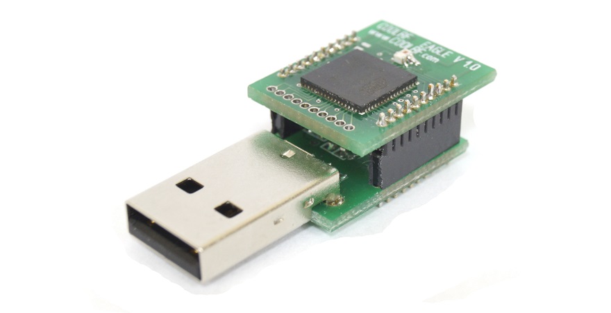
While the first parcels with our modules are going to their customers, we have prepared an article that will help them assemble them (if they purchased the kit for self-assembly) or remove questions about the circuitry (if modules are assembled). The photo shows our USB adapter, which can be purchased either as a designer or fully assembled and ready to go.
A brief introduction to the course for those who first saw our project
We are developing a complete system of smart home. The “first sign” of our system is a DIY-dimmer. Here are its main characteristics:
If you want to join in the discussion of the features of the system, please read all our previous articles and comments to them. Most likely the questions after such an introduction will be much less.
- 2.4 GHz radio channel operation (own protocol, without licensing restrictions, or ZigBee implementation based on Atmtel BitCloud)
- Encrypted connection
- Installation without changing the standard wiring of an ordinary apartment
- Low power consumption
- The usual look of switches
- The possibility of independent expansion of both hardware and software functionality
- Open source code of both software and hardware
If you want to join in the discussion of the features of the system, please read all our previous articles and comments to them. Most likely the questions after such an introduction will be much less.
Want to keep abreast of all project events? It is not difficult at all!
You just need to subscribe to the update of our company in Habré and in the VKontakte group .
')
With VKontakte questions usually does not arise. To subscribe to Habr's updates, you need to go to the company’s page and click the “Subscribe” button in the block on the right.
')
With VKontakte questions usually does not arise. To subscribe to Habr's updates, you need to go to the company’s page and click the “Subscribe” button in the block on the right.
Circuit radio module COOLRF EGLE
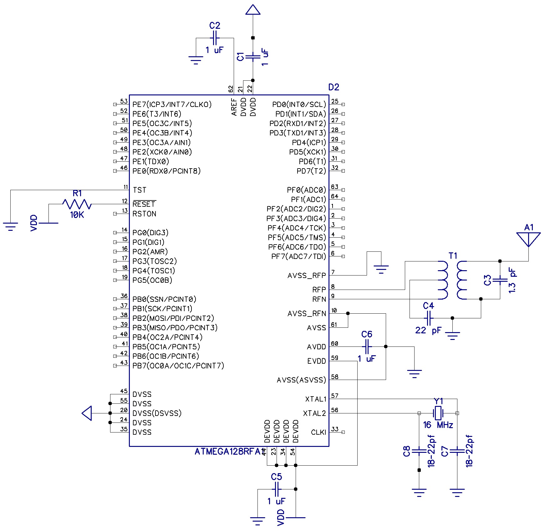
The heart of our dimmer DMMR is the COOLRF EGLE radio module on the Atmega128RFA1 chip. The scheme of its inclusion is taken from the datasheet, with minor changes:
- Quartz quartz is not used, but nevertheless a place for its installation on the board is provided;
- The radio part was taken from the datasheet manufacturer of the matching transformer (balun - use Atmel's recommended Atmega128RFA1 chip).
Layout of components of the scheme:
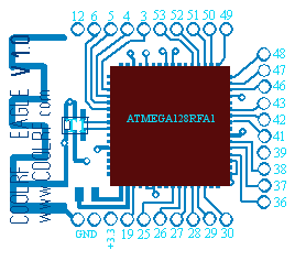 top
top 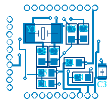 bottom
When designing the board, it was supposed to use a quartz resonator (Y1) in case 6035, but after their manufacture, we were offered a resonator in another case 3225 - after some research, we successfully installed it, setting the case at an angle (the resonator in the case was installed diagonally) .
It is worth noting some elements of the matching part of the radio - capacitors C3 and C4. Since We have an antenna on the board, we need to create an impedance for our carrier frequency (2.4 GHz) of 50 Ohms - this is achieved by selecting the capacitor C3, its rated value should be in the range from 0.5 to 1.5 pF. Capacitor C4 is the matching between the transformer and the microcontroller - 22 pF according to the recommendation of the transformer manufacturer, but as the practice of other manufacturers shows, it is not necessary, and the output of the transformer is grounded.
COOLRF EGLE USB USB Strapping
The controller we have chosen has a good supply of flash memory (128Kb) and performance, but does not have USB hardware. We used the software implementation of the USB protocol - the VUSB library from (obdev). The undoubted advantage of this implementation is a simple strapping (at a minimum only 4 resistors are needed) and a well-documented library.
Binding scheme for our radio module:
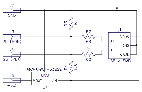
The elements on the board are as follows:
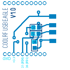 top
top  bottom
Unfortunately, when designing, we made a number of non-fatal and easily fixable errors that came to light when we received the boards:
- According to obdev recommendation, it is necessary to put a smoothing capacitor on the power supply, due to an error in the design, we cannot use it, but this does not affect the quality of the USB device;
- the stabilizer seat (U1) turned upside down, the exit - when installing the stabilizer, it is necessary to bend its legs in the opposite direction.
PS
Great news - our first batch of Atmega128RFA1 chips arrived. Now we can satisfy your interest, send your applications by mail , while our site is under construction.
We are preparing articles on the programming of our hardware. In the near future, we will show how to work with the radio from the microcontroller firmware and how to work with the “whistle” via USB from the computer. See you again!
Source: https://habr.com/ru/post/210750/
All Articles