HID USB Device Management on Windows 7
The article attempts to provide step-by-step instructions on how to connect an improvised USB HID device on an AVR microcontroller and a Windows 7 x64- based computer to exchange data and control microcontroller ports. The sample application controls the microcontroller port via USB (an indicator LED is connected to it). It is also possible to read the status of the state of the LED - it is extinguished or on. The topic is intended for beginners, so a big request to programming connoisseurs is to save rotten eggs and rotten tomatoes with ironic comments for a better opportunity.
1 . For the microcontroller, the V-USB [1] library from Objective Development and the Atmel Studio 6 [2] by Atmel. It is also necessary to download and install WinAVR [3] toolchain to compile the microcontroller's firmware (for specialists this is not necessary, because you can do with the toolchain, which is part of Atmel Studio).
2 For writing a Windows program (host software), LibUsbDotNet [4] was used by Travis Robinson and IDE Visual Studio C # 2010 [5] by Microsoft.
All software except Visual Studio 2010 is free, although it is possible to use Visual Studio C # 2010 Express for free for a limited time. All actions were carried out in the environment of the Windows 7 x64 operating system, but any other operating system of the Windows family (Windows XP and later) will most certainly do.
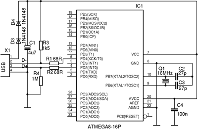
Thanks to the V-USB library, any AVR microcontroller can be used to create a USB HID device. If you are friends with a soldering iron, you can even build a USB connection yourself using one of the published schemes. Such a scheme (taken from the V-USB package [1]) is shown in the picture as an example.
')
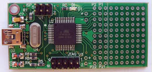
To save time and effort, it is better to use a ready-made breadboard. It is especially convenient if the USB bootloader (bootloader) is written to the board, then you don’t need to buy a programmer to flash the board. I used the AVR-USB-MEGA16 prototype board with an ATmega32A microcontroller, it has a bootloader (USBasploader, which emulates the behavior of the USBasp programmer). This is how a scarf looks life-size:
You can also take a metaboard (it has an ATmega168 or ATmega328 on it), or even a programmer on an ATmega8 microcontroller. These glands can be bought cheaply on ebay.com or dx.com .
Make a new project in Atmel Studio 6 (hereinafter simply AS6). When AS6 offers to choose a microcontroller, select Atmega32 without the letter A , not Atmega32A (although the Atmega32A is on the board) - this is important, since WinAVR does not see a difference, it only knows Atmega32. These internal microcontrollers are identical, so for us there is no difference, but for AS6 there is.
Now you need to properly configure the compiler. In the top menu of AS6, click Tools , then Options .. and this window will appear:
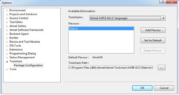
On the left in the list, select Toolchain . A list of Flavors appears on the right. With this word Atmel has coded the possible variants of the tools used (toolchains).
To add the WinAVR toolbar to the Flavors list, click the Add Flavor button, the following window will appear:
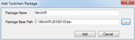
In the top line of this window, type the name of the WinAVR compiler (arbitrary), and on the bottom line, enter the full path where the toolchain compiler itself is installed (with the \ bin folder indicated) and click the Add button. The added compiler appears in the Flavors list, as shown in the screenshot.

Highlight our newly added WinAVR compiler with your mouse and click the Set As Default button (click to make it the default), and click OK. After this procedure, our AS6 will use the WinAVR compiler.
It's time to adjust the properties of our project. To do this, left-click the project name in the Solution Explorer and press Alt + F7 (Project -> Properties menu), a window with settings will appear:
Make the following settings:
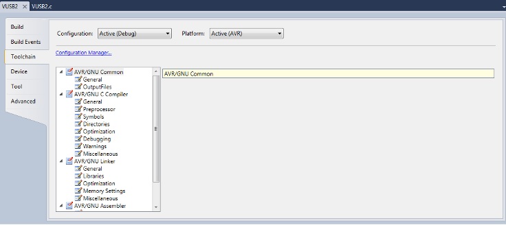
Further, a very important point - in the left part of the window, select the Advanced section in the list, as shown in the figure below.
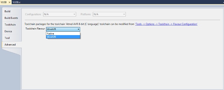
In the Toolchain Flavor drop-down list, select the added WinAVR compiler, so that AS6 compiles the project using it. At this point, the AS6 setup is complete.
Next, you need to add the project [6] source code files to the created project - see the folder firmware \ VUSB, the files VUSB.c, usbdrv.c, usbdrvasm.S and oddebug.c. The ASS6 project is based on one of the examples of the V-USB library: hid-custom-rq, which was originally compiled using the command line make utility. Based on the V-USB library, you can find many other code examples - mostly USB HID devices (mice, keyboards, input and output devices), but there are also USB CDC devices (virtual COM port). If you are too lazy to create a project yourself, simply open the VUSB.atsln project file in AS6, it has already made all the necessary settings and added all the necessary files.
If you use another breadboard, then you need to properly configure the usbconfig.h file. This is the V-USB library configuration file, it contains many settings and parameters (VID, PID, microcontroller legs, values for descriptors and other settings). A detailed description of all the settings is given in the comments of this file. The main attention should be paid to the pin assignment of the microcontroller, which is used for the signals USD D + and D- (macros USB_CFG_IOPORTNAME, USB_CFG_DMINUS_BIT, USB_CFG_DPLUS_BIT), these legs have special requirements. The usbconfig.h configuration file from the archive [6] is intended for wiring the legs of the AVR-USB-MEGA16 prototype board, and it is guaranteed to work. The program will blink with the LED that already exists on the breadboard and is connected to pin 0 of port B.
Our program should send packets that will control the microcontroller via USB connection.
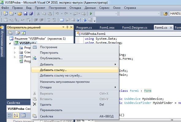
Start Microsoft Visual C # 2010 Express and create a new project based on a Windows Form. Now we need to connect the library LibUsbDotNet.dll to the project. In Solution Explorer, right-click on the project name, and select "Add Link."
another window will appear
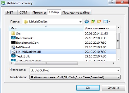
here you need to find the path on the disk where the LinUsbDotNet.dll library is located (by default it is installed in the C: \ Program Files \ LibUsbDotNet folder, but it’s better to make a copy of the DLL file in the working directory of the project. After connecting the library, you must declare it in the project, add In the main module of the program (file Form1.cs) the lines:
Go to the visual form editor, and bring it to approximately this form (add 3 buttons Button and 3 text labels Label):

Make a form load event handler. It is needed so that when the program starts, an instance of the LibUsbDotNet class is initialized through which it is exchanged with a USB device. Before the exchange, it is necessary to open access to our device, because several USB HID devices can be connected to the computer, and you should be able to contact each individual. For identifying USB devices, special identifiers are used that have absolutely all USB devices, these are VID and PID.
The VID is the vendor ID (Vendor ID), and the PID is the device ID (Product ID). Our USB device has a VID: 0x 16C0 , PID: 0x 05DF , these values are indicated in the usbconfig.h configuration file (we already mentioned this file) of the AS6 microcontroller project. In order for the host software to access our USB device, you need to initialize the MyUsbFinder object with the same VID parameters: 0x16c0, PID: 0x05df, as specified in the usbconfig.h file. To do this, add the following code to the scope of the global variables of the Form1 class:
Once we have decided on which USB device we will work with, we can connect to it, and it is convenient to do this at the time the program starts (opening the form window). To do this, select the main form of the program, and in the property editor create a handler for the loading event Form1_Load. In the body of the handler enter the following code:
Make an event handler for the click on the button1 button (“On”), for this, in the visual editor of the button, double-click, and add the code to the body of the event handler:
For the handler of the "Off" button, add the code:
The code for processing the "Read" button:
The event handler for the form closing (program shutdown) extinguishes the LED if it is lit:
The reception and processing of data on the side of the microcontroller is carried out in the usbFunctionSetup function (located in the main module VUSB.c of the AS6 firmware project). Here is the function:
Our USB HID device is the simplest, and it responds only to control transfer (control transfer) that passes through endpoint 0 (default control endpoint). The type of request (bRequest field) decodes the direction of data transfer. If CUSTOM_RQ_SET_STATUS, then this is the data intended for the microcontroller. The data is decoded and the microcontroller executes the command laid there. In this case, the state of the LED is encoded in the very first received byte of data - if there is one in the low-order bit, then the LED turns on, and if it is zero, it goes out. If CUSTOM_RQ_GET_STATUS is taken in the bRequest field, then the buffer is filled with the current LED status in response, and the buffer data is sent back to the host. Everything is very simple, and, if desired, the behavior of the code can be easily altered to fit your needs.
Video, how it works:
I will be glad to answer in the comments questions and constructive comments.
1 . V-USB .
2 Atmel Studio 6 .
3 WinAVR .
4 LibUsbDotNet C # USB Library .
5 Visual Studio 2010 Express .
6 The source code for the microcontroller and for the host software .
PS The impetus to the knowledge was the site microsin.net , where there was a lot of information on the USB protocols and practical application of microcontrollers in USB devices. Thank you so much! the developer of this site for their responsiveness and assistance in matters relating to this subject.
In the future, if possible, I plan to do the same, but on a microcontroller with a hardware USB interface.
Used software
1 . For the microcontroller, the V-USB [1] library from Objective Development and the Atmel Studio 6 [2] by Atmel. It is also necessary to download and install WinAVR [3] toolchain to compile the microcontroller's firmware (for specialists this is not necessary, because you can do with the toolchain, which is part of Atmel Studio).
2 For writing a Windows program (host software), LibUsbDotNet [4] was used by Travis Robinson and IDE Visual Studio C # 2010 [5] by Microsoft.
All software except Visual Studio 2010 is free, although it is possible to use Visual Studio C # 2010 Express for free for a limited time. All actions were carried out in the environment of the Windows 7 x64 operating system, but any other operating system of the Windows family (Windows XP and later) will most certainly do.
Iron used
Thanks to the V-USB library, any AVR microcontroller can be used to create a USB HID device. If you are friends with a soldering iron, you can even build a USB connection yourself using one of the published schemes. Such a scheme (taken from the V-USB package [1]) is shown in the picture as an example.
')
To save time and effort, it is better to use a ready-made breadboard. It is especially convenient if the USB bootloader (bootloader) is written to the board, then you don’t need to buy a programmer to flash the board. I used the AVR-USB-MEGA16 prototype board with an ATmega32A microcontroller, it has a bootloader (USBasploader, which emulates the behavior of the USBasp programmer). This is how a scarf looks life-size:
You can also take a metaboard (it has an ATmega168 or ATmega328 on it), or even a programmer on an ATmega8 microcontroller. These glands can be bought cheaply on ebay.com or dx.com .
Microcontroller firmware creation using Atmel Studio 6 and V-USB library
Make a new project in Atmel Studio 6 (hereinafter simply AS6). When AS6 offers to choose a microcontroller, select Atmega32 without the letter A , not Atmega32A (although the Atmega32A is on the board) - this is important, since WinAVR does not see a difference, it only knows Atmega32. These internal microcontrollers are identical, so for us there is no difference, but for AS6 there is.
Now you need to properly configure the compiler. In the top menu of AS6, click Tools , then Options .. and this window will appear:
On the left in the list, select Toolchain . A list of Flavors appears on the right. With this word Atmel has coded the possible variants of the tools used (toolchains).
. Native, (Default). Native - GCC , . Atmel, AS6. , , V-USB ( USB HID USB) . , WinAVR, . To add the WinAVR toolbar to the Flavors list, click the Add Flavor button, the following window will appear:
In the top line of this window, type the name of the WinAVR compiler (arbitrary), and on the bottom line, enter the full path where the toolchain compiler itself is installed (with the \ bin folder indicated) and click the Add button. The added compiler appears in the Flavors list, as shown in the screenshot.
Highlight our newly added WinAVR compiler with your mouse and click the Set As Default button (click to make it the default), and click OK. After this procedure, our AS6 will use the WinAVR compiler.
It's time to adjust the properties of our project. To do this, left-click the project name in the Solution Explorer and press Alt + F7 (Project -> Properties menu), a window with settings will appear:
Make the following settings:
- In the AVR / GNU C Compiler -> Symbols section, add the F_CPU = 12000000UL line to the -D field - this corresponds to a microcontroller frequency of 12 MHz (such quartz is installed on my AVR-USB-MEGA16 development board).
- In the section AVR / GNU Assemler -> General in the field Assembler flag you must add -DF_CPU = 12000000UL .
- In the section AVR / GNU C Compiler -> Optimization in the Optimization Level field should be Optimize for size (-Os) .
Further, a very important point - in the left part of the window, select the Advanced section in the list, as shown in the figure below.
In the Toolchain Flavor drop-down list, select the added WinAVR compiler, so that AS6 compiles the project using it. At this point, the AS6 setup is complete.
Next, you need to add the project [6] source code files to the created project - see the folder firmware \ VUSB, the files VUSB.c, usbdrv.c, usbdrvasm.S and oddebug.c. The ASS6 project is based on one of the examples of the V-USB library: hid-custom-rq, which was originally compiled using the command line make utility. Based on the V-USB library, you can find many other code examples - mostly USB HID devices (mice, keyboards, input and output devices), but there are also USB CDC devices (virtual COM port). If you are too lazy to create a project yourself, simply open the VUSB.atsln project file in AS6, it has already made all the necessary settings and added all the necessary files.
If you use another breadboard, then you need to properly configure the usbconfig.h file. This is the V-USB library configuration file, it contains many settings and parameters (VID, PID, microcontroller legs, values for descriptors and other settings). A detailed description of all the settings is given in the comments of this file. The main attention should be paid to the pin assignment of the microcontroller, which is used for the signals USD D + and D- (macros USB_CFG_IOPORTNAME, USB_CFG_DMINUS_BIT, USB_CFG_DPLUS_BIT), these legs have special requirements. The usbconfig.h configuration file from the archive [6] is intended for wiring the legs of the AVR-USB-MEGA16 prototype board, and it is guaranteed to work. The program will blink with the LED that already exists on the breadboard and is connected to pin 0 of port B.
Creating a program for the computer (host software)
Our program should send packets that will control the microcontroller via USB connection.
. V-USB. makefile MinGW, LibUSB. Visual Studio LibUsbDotNet. LibUsbDotNet , , . - , LibUSB . , , - LibUSB, USB Windows. . Start Microsoft Visual C # 2010 Express and create a new project based on a Windows Form. Now we need to connect the library LibUsbDotNet.dll to the project. In Solution Explorer, right-click on the project name, and select "Add Link."
another window will appear
here you need to find the path on the disk where the LinUsbDotNet.dll library is located (by default it is installed in the C: \ Program Files \ LibUsbDotNet folder, but it’s better to make a copy of the DLL file in the working directory of the project. After connecting the library, you must declare it in the project, add In the main module of the program (file Form1.cs) the lines:
using LibUsbDotNet; using LibUsbDotNet.Info; using LibUsbDotNet.Main; Go to the visual form editor, and bring it to approximately this form (add 3 buttons Button and 3 text labels Label):
Make a form load event handler. It is needed so that when the program starts, an instance of the LibUsbDotNet class is initialized through which it is exchanged with a USB device. Before the exchange, it is necessary to open access to our device, because several USB HID devices can be connected to the computer, and you should be able to contact each individual. For identifying USB devices, special identifiers are used that have absolutely all USB devices, these are VID and PID.
. - USB VID PID, . USB-, , VID/PID, , . The VID is the vendor ID (Vendor ID), and the PID is the device ID (Product ID). Our USB device has a VID: 0x 16C0 , PID: 0x 05DF , these values are indicated in the usbconfig.h configuration file (we already mentioned this file) of the AS6 microcontroller project. In order for the host software to access our USB device, you need to initialize the MyUsbFinder object with the same VID parameters: 0x16c0, PID: 0x05df, as specified in the usbconfig.h file. To do this, add the following code to the scope of the global variables of the Form1 class:
public static UsbDevice MyUsbDevice; public static UsbDeviceFinder MyUsbFinder = new UsbDeviceFinder(0x16c0, 0x05df); Once we have decided on which USB device we will work with, we can connect to it, and it is convenient to do this at the time the program starts (opening the form window). To do this, select the main form of the program, and in the property editor create a handler for the loading event Form1_Load. In the body of the handler enter the following code:
private void Form1_Load(object sender, EventArgs e) { MyUsbDevice = UsbDevice.OpenUsbDevice(MyUsbFinder); if (MyUsbDevice != null) { label2.Text = " !"; } else label2.Text = " !"; } Make an event handler for the click on the button1 button (“On”), for this, in the visual editor of the button, double-click, and add the code to the body of the event handler:
private void button1_Click(object sender, EventArgs e) { // , AVR-USB-MEGA16. UsbSetupPacket packet = new UsbSetupPacket((byte)(UsbCtrlFlags.RequestType_Vendor | UsbCtrlFlags.Recipient_Device | UsbCtrlFlags.Direction_Out), 1, (short)1, 0, 0); int countIn; byte[] data = new byte[1]; MyUsbDevice.ControlTransfer(ref packet, data, 0, out countIn); } For the handler of the "Off" button, add the code:
private void button3_Click(object sender, EventArgs e) { // , AVR-USB-MEGA16. UsbSetupPacket packet = new UsbSetupPacket((byte)(UsbCtrlFlags.RequestType_Vendor | UsbCtrlFlags.Recipient_Device | UsbCtrlFlags.Direction_Out), 1, (short)0, 0, 0); int countIn; byte[] data = new byte[1]; MyUsbDevice.ControlTransfer(ref packet, data, 0, out countIn); } The code for processing the "Read" button:
private void button2_Click(object sender, EventArgs e) { // AVR-USB-MEGA16 - . UsbSetupPacket packet = new UsbSetupPacket((byte)(UsbCtrlFlags.RequestType_Vendor | UsbCtrlFlags.Recipient_Device | UsbCtrlFlags.Direction_In), 2, (short)0, (short)0, (short)0); int countIn; byte[] data = new byte[1]; if (MyUsbDevice.ControlTransfer(ref packet, data, 1, out countIn) && (countIn == 1)) { label3.Text = " " + data[0].ToString(); } } The event handler for the form closing (program shutdown) extinguishes the LED if it is lit:
private void Form1_FormClosed(object sender, FormClosedEventArgs e) { UsbSetupPacket packet = new UsbSetupPacket((byte)(UsbCtrlFlags.RequestType_Vendor | UsbCtrlFlags.Recipient_Device | UsbCtrlFlags.Direction_Out), 1, (short)0, 0, 0); int countIn; byte[] data = new byte[1]; MyUsbDevice.ControlTransfer(ref packet, data, 0, out countIn); } How USB packages are decoded into the microcontroller's firmware
The reception and processing of data on the side of the microcontroller is carried out in the usbFunctionSetup function (located in the main module VUSB.c of the AS6 firmware project). Here is the function:
usbMsgLen_t usbFunctionSetup(uchar data[8]) { usbRequest_t *rq = (void *)data; if((rq->bmRequestType & USBRQ_TYPE_MASK) == USBRQ_TYPE_VENDOR){ DBG1(0x50, &rq->bRequest, 1); /* : */ if(rq->bRequest == CUSTOM_RQ_SET_STATUS){ if(rq->wValue.bytes[0] & 1){ /* LED */ LED_PORT_OUTPUT |= _BV(LED_BIT); }else{ /* LED */ LED_PORT_OUTPUT &= ~_BV(LED_BIT); } }else if(rq->bRequest == CUSTOM_RQ_GET_STATUS){ static uchar dataBuffer[1]; /* usbFunctionSetup */ dataBuffer[0] = ((LED_PORT_OUTPUT & _BV(LED_BIT)) != 0); usbMsgPtr = dataBuffer; /* , */ return 1; /* 1 */ } }else{ /* USBRQ_HID_GET_REPORT USBRQ_HID_SET_REPORT , * . , * . */ } return 0; /* default : */ } Our USB HID device is the simplest, and it responds only to control transfer (control transfer) that passes through endpoint 0 (default control endpoint). The type of request (bRequest field) decodes the direction of data transfer. If CUSTOM_RQ_SET_STATUS, then this is the data intended for the microcontroller. The data is decoded and the microcontroller executes the command laid there. In this case, the state of the LED is encoded in the very first received byte of data - if there is one in the low-order bit, then the LED turns on, and if it is zero, it goes out. If CUSTOM_RQ_GET_STATUS is taken in the bRequest field, then the buffer is filled with the current LED status in response, and the buffer data is sent back to the host. Everything is very simple, and, if desired, the behavior of the code can be easily altered to fit your needs.
Video, how it works:
I will be glad to answer in the comments questions and constructive comments.
Links
1 . V-USB .
2 Atmel Studio 6 .
3 WinAVR .
4 LibUsbDotNet C # USB Library .
5 Visual Studio 2010 Express .
6 The source code for the microcontroller and for the host software .
PS The impetus to the knowledge was the site microsin.net , where there was a lot of information on the USB protocols and practical application of microcontrollers in USB devices. Thank you so much! the developer of this site for their responsiveness and assistance in matters relating to this subject.
In the future, if possible, I plan to do the same, but on a microcontroller with a hardware USB interface.
Source: https://habr.com/ru/post/210736/
All Articles