Visualization with RGB strip
So, dear friends, I'll start a little from afar. I decided to order a cheap STMF4-DISCOVERY debugging handkerchief from eBay from America, I waited a long time, I wanted to play around with the F4 series controller, but a month later at the post office I was bummed. Natural crap came instead of delicious shawls - RGB strip based on the WS2801 controller. The strip is waterproof with connectors and addressable LEDs separately, but first things first!
The first thing you need to try it in! Let's get started!

')
What kind of applications can you find this bad thing? Not many looking online, the following uses of the band were identified:
Thus, for our simple test project, we will choose an option that will work perfectly on the table and spend not much time and money on solving the problem.
So, the goal will be: the creation of an informer band showing the processor load or any other value.
To solve the problem we need:
As a controller, I found in my desk Arduino Nano, which had not been used for a long time to use for something valuable. In addition to the scarves, there was also a layout with stuck conductors, which means you can create.
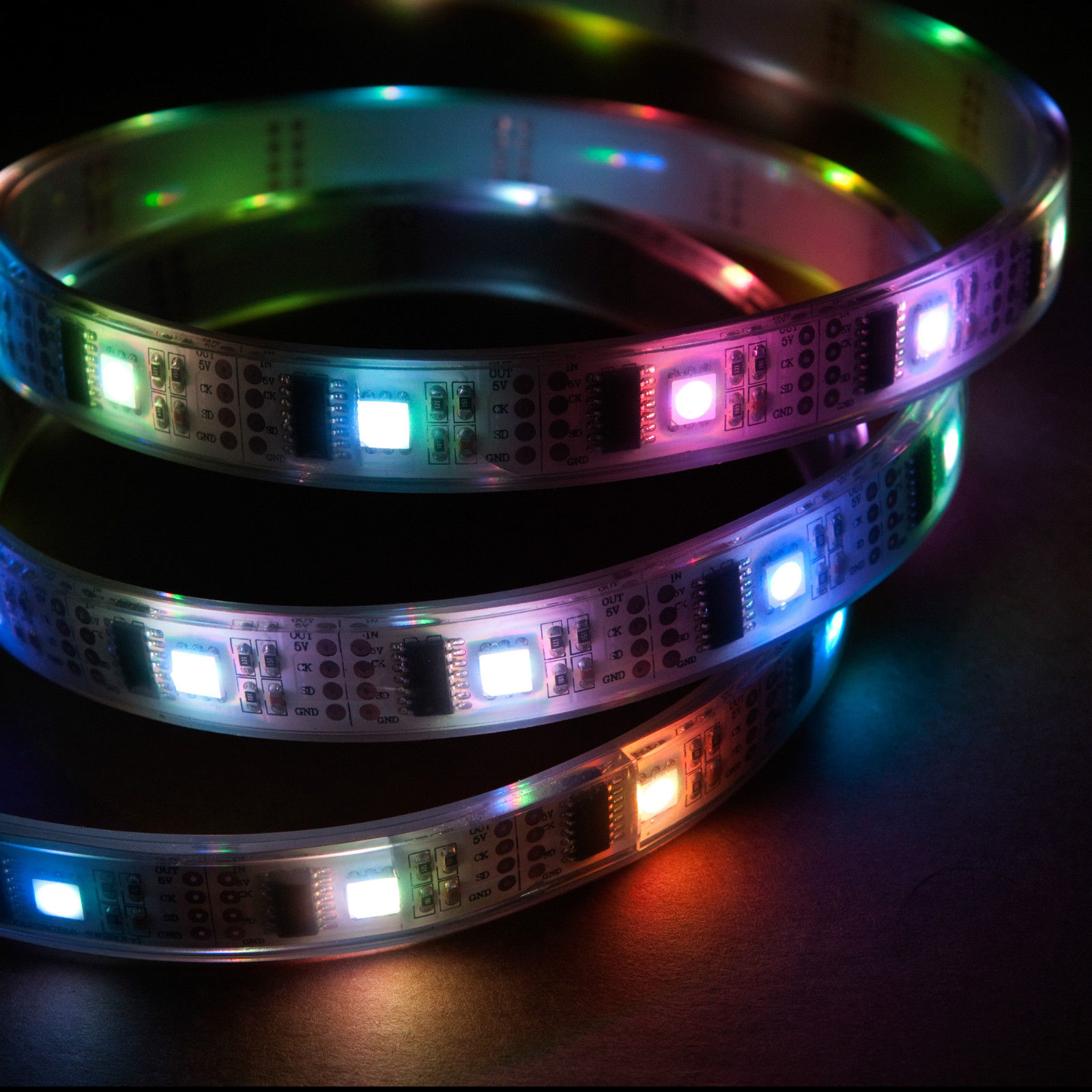
Judging by the description of the seller cents, it is built on the controllers WS2801, controlled by SPI or I2C, the choice of the developer. An interesting feature of this tape are RGB diodes and separately controlled IC drivers. They are controlled by a sequence of shipments, by the number of strip segments. The timing chart is attached below:

As can be seen from the figure, one chip expects three bytes of brightness for each channel. If the data is transmitted without pauses, then after the capture of the package, each microcircuit begins to output a sequence for the next receiver.
The pinout is written on the tape itself and in the description, so there’s nothing complicated about it:
We connect our ribbon directly to the controller on the breadboard, as shown in the figure:

As a final touch, we fix tape ends with tape to make a ring.
It’s not difficult to write our own implementation of the control protocol for the band, but since we didn’t have much time to spend, we ’ll turn to the ready-made FastLED control strip library that is ported to many controllers and supports various LED drivers in the strips.
The hardware must meet the following requirements:
The first requirement is very important, because beautiful effects should not block the program, i.e. immediately after receiving the data from the port, the command must be processed and the behavior must change. Thus, the use of the delay function for a specified time is excluded; it will only be used to set a delay of 1 ms after the entire tape has been filled.
The tape control protocol includes the following commands:
As a response, echo strings of commands starting with the characters " >> " are returned, for example:
The tape object is configured in the setup function, I will give it below:
For example, here is the implementation of the non-blocking snake rendering function:
Operating modes we implement the following:
In order not to suffer for a long time, you can rivet a C # control program that implements the protocol:

The program implements the above described control protocol and the ability with a specified period to send the value of the processor load and full memory (the current network speed in the plans).
So, this whole farm needs to be checked, for which purpose we will use the Hot CPU Tester 4.3 processor free test utility, the composition of the tests was specially cut, so that the “live” change in the tape effects could be seen. The list of tests is shown in the picture:

The test results and the functioning of the informer can be viewed on the video:
Source:
LEDInformer.rar
I plan to use this device either in the car, or to decorate the inside of the High Tower of my company, in order to show what is happening to it with beautiful colors!
The first thing you need to try it in! Let's get started!
')
What kind of applications can you find this bad thing? Not many looking online, the following uses of the band were identified:
- Incomprehensible thing for pampering and bullying colleagues
- Decorative lighting (car, window, cottage, etc.)
- Visual display of a parameter (sound, voltage, frequency, load, etc.)
Thus, for our simple test project, we will choose an option that will work perfectly on the table and spend not much time and money on solving the problem.
So, the goal will be: the creation of an informer band showing the processor load or any other value.
To solve the problem we need:
- Arduino nano
- Bread board
- Several conductors
- Insulating tape
- Mini usb cable
Stage 1. Hardware
As a controller, I found in my desk Arduino Nano, which had not been used for a long time to use for something valuable. In addition to the scarves, there was also a layout with stuck conductors, which means you can create.
Judging by the description of the seller cents, it is built on the controllers WS2801, controlled by SPI or I2C, the choice of the developer. An interesting feature of this tape are RGB diodes and separately controlled IC drivers. They are controlled by a sequence of shipments, by the number of strip segments. The timing chart is attached below:
As can be seen from the figure, one chip expects three bytes of brightness for each channel. If the data is transmitted without pauses, then after the capture of the package, each microcircuit begins to output a sequence for the next receiver.
The pinout is written on the tape itself and in the description, so there’s nothing complicated about it:
- Red 5V DC
- Green Clock
- Yellow Data
- Brown Ground
We connect our ribbon directly to the controller on the breadboard, as shown in the figure:
As a final touch, we fix tape ends with tape to make a ring.
Stage 2. Programming hardware and software
It’s not difficult to write our own implementation of the control protocol for the band, but since we didn’t have much time to spend, we ’ll turn to the ready-made FastLED control strip library that is ported to many controllers and supports various LED drivers in the strips.
The hardware must meet the following requirements:
- The main loop of the program should not be blocked
- The control protocol should be simple and clear.
- The device operates in SLAVE mode
The first requirement is very important, because beautiful effects should not block the program, i.e. immediately after receiving the data from the port, the command must be processed and the behavior must change. Thus, the use of the delay function for a specified time is excluded; it will only be used to set a delay of 1 ms after the entire tape has been filled.
The tape control protocol includes the following commands:
| SET MODE% d \ n | Set the operation mode |
| SET COLOR% d \ n | Set Primary Color |
| SET VALUE% d \ n | Set a value from 0 to 1000 |
As a response, echo strings of commands starting with the characters " >> " are returned, for example:
>> SET VALUE 673 The tape object is configured in the setup function, I will give it below:
void setup() { Serial.begin(115200); // , , ., , FastLED.addLeds<WS2801, DATA_PIN, CLOCK_PIN, RGB>(leds, NUM_LEDS); } For example, here is the implementation of the non-blocking snake rendering function:
void runner(CRGB color, int period, uint8_t s) { static int pos = 0; /* */ static long last = millis(); if(millis() - last > period) { // last = millis(); clear_led(); if(pos < NUM_LEDS - s) { // for(uint8_t j = 0; j < s; ++j) { leds[pos + j] = color; } FastLED.show(); ++pos; } else { pos = 0; } } } Operating modes we implement the following:
- Running segment with a given offset rate
- Filling the tape with a specified color for a given length
- Filling the tape with a color change depending on the value (0 - 300 green, 301 - 660 yellow, 661 - 1000 red)
- Running segment with a given displacement rate with differently changing colors
- Filling the tape with a given color for a given length with differently changing colors
- Color check mode according to FastLED library documentation
In order not to suffer for a long time, you can rivet a C # control program that implements the protocol:
The program implements the above described control protocol and the ability with a specified period to send the value of the processor load and full memory (the current network speed in the plans).
Stage 3. Debugging and Testing
So, this whole farm needs to be checked, for which purpose we will use the Hot CPU Tester 4.3 processor free test utility, the composition of the tests was specially cut, so that the “live” change in the tape effects could be seen. The list of tests is shown in the picture:
The test results and the functioning of the informer can be viewed on the video:
Source:
LEDInformer.rar
I plan to use this device either in the car, or to decorate the inside of the High Tower of my company, in order to show what is happening to it with beautiful colors!
Source: https://habr.com/ru/post/210360/
All Articles