Motorized slider for shooting timelapse
Prehistory
Hello, hello. Watching the video with motorized sliders, I wanted to skolhozit and such a miracle. The slider itself was assembled with a friend last summer, and at the same time they wanted to fasten the engine to it, but unfortunately the hands did not reach. After removing a few timelapse, I realized that without a motor, all this is boring and dull. But the vacation was over and the whole thing was put in the closet.
Selection and purchase of the engine. Samples and errors
At first, I wanted to adapt the bipolar stepper motor from the old Kenonovskaya MFP-shki, in which the footsteps stood on the drive for gripping and pulling the paper, as well as in the scanner. It would be possible to connect them through Arduino, fill in the firmware and all that ... But, having a little googling on this topic and after consulting on specialized forums, I realized that building it on Arduino is the same as “shooting a gun at the flies”.
It was decided to purchase a servo drive and a tester for him, who knew how to regulate the engine speed. The drive is powered from 4.8V to 6V, as well as the tester, which suited me perfectly. Hurrying, I ordered the SM-S4306R servo and tester. But I hurried because I did not think what kind of load would fall on the gearbox, which is made entirely of plastic. The arrived drive was checked and taken home. The next day I wanted to test its capabilities and when literally at 3m connecting the drive to power from 4x Sanyo Eneloop AA batteries, something inside it slightly slammed and zavonyalo… After an autopsy, an exploding piece was found that immediately warmed up and creepy when I opened the power supply smelled. Okay.
')
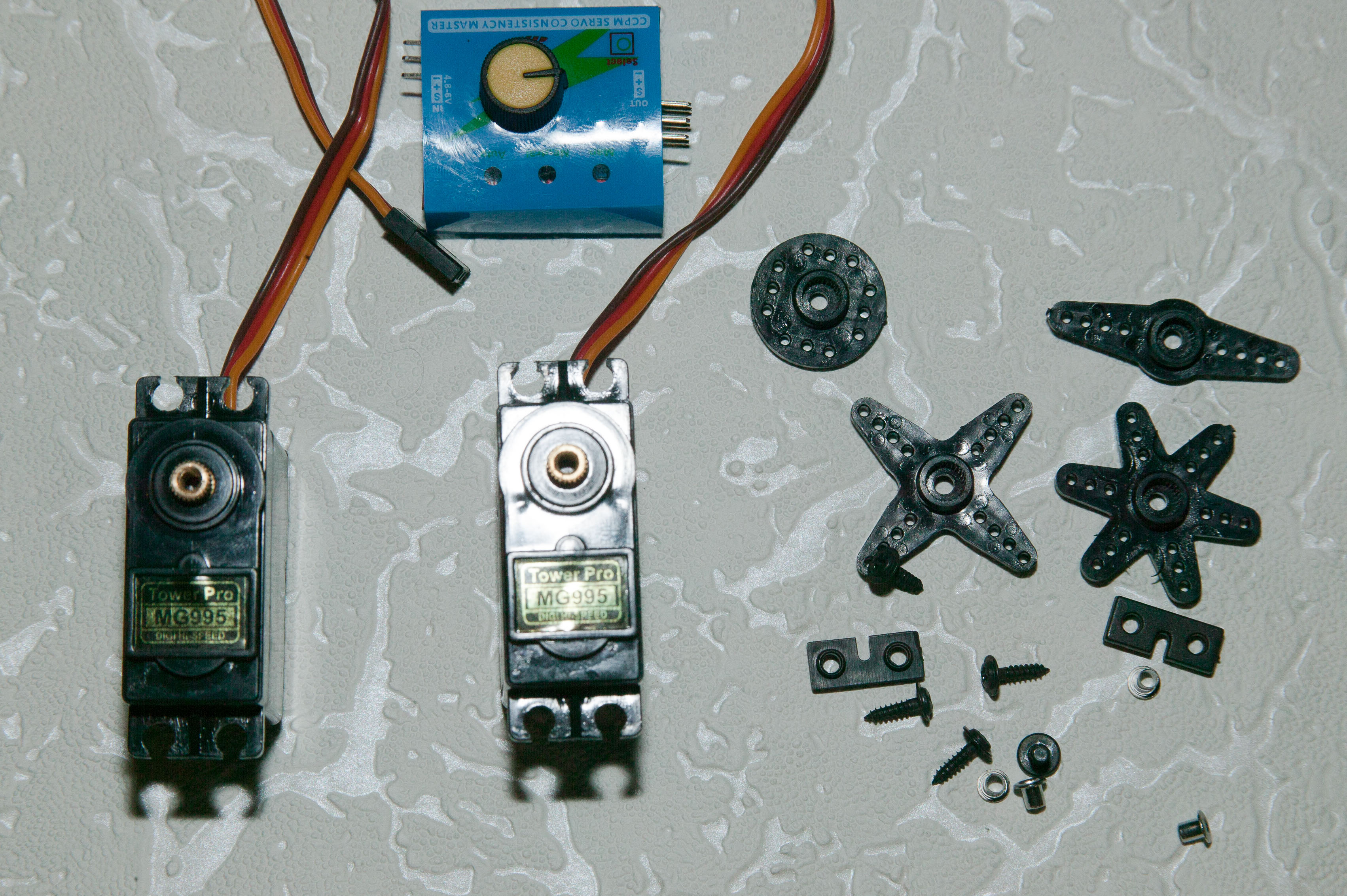
Having come to terms with the dead drive, I ordered two Futaba T306 MG995 servo drives with the following parameters:
Double row ball bearing
Dimensions: 40mm x 19mm x 43mm
Weight: 55 g
Work speed: 0.17sec / 60 degrees (4.8 without load)
Work speed: 0.13sec / 60 degrees (6.0V without load)
Moment: 13 kg-cm at 4.8V
Moment: 15 kg-cm at 6V
Operating voltage: 4.8 - 7.2V
The most remarkable thing about this drive was that all its gears were made of metal, which was exactly what was required for my tasks. As it turned out later - 15 kg / cm was not at all superfluous.
And here are the servos themselves with the tester:
Fine. Only plugging again. As it turned out, these drives have 2 modifications. One at 180 ° and 360 °. Well, you understand, right? Naturally, I acquired at 180 °. Well…
Turn the drive 180 ° into the drive 360 °
After googling, it was discovered that there is a hack of this servo and it is done in literally 10-15 minutes. Who cares - see the video below, but I’ll say right away, everything is told and shown there for a very long time. Although, for Americans, this is probably the way to be explained. Video filmed with trembling hands apparently the son of that American.
The whole point is that it is necessary to disconnect the engine position sensor and solder 2 resistors for 2.2 kΩ instead. Just saw off / pull the pin out of one gear.
Hack MG995:
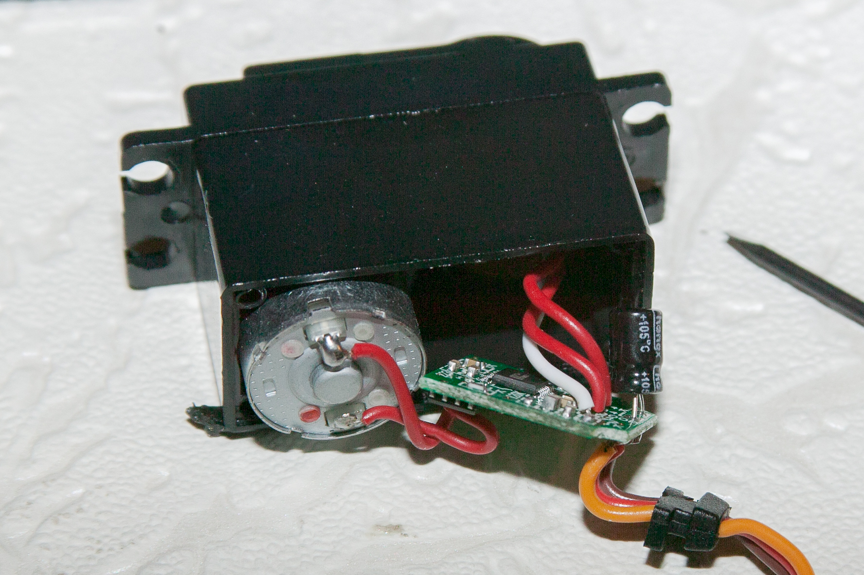
A guide to action was received and I began to kill the servos. The first step was to remove the pin on the gear, which is on the bottom of the photo. I did not manage to pull it out, but it was cut off on sandpaper almost immediately.

From it, the plastic insert was removed, which twisted the engine position sensor.

So ... With the mechanical part it was over.

It's time to kill the electric. The motor position sensor has three contacts that need to be removed and soldered resistors. I have to say that putting the resistors at 2.2 kΩ the tester began to turn the drive in one direction only, which did not suit me. Putting 5 kΩ resistors instead of 2.2, I returned the tester's ability to do reverse. The photo is still at 2.2 ohms.

Slider
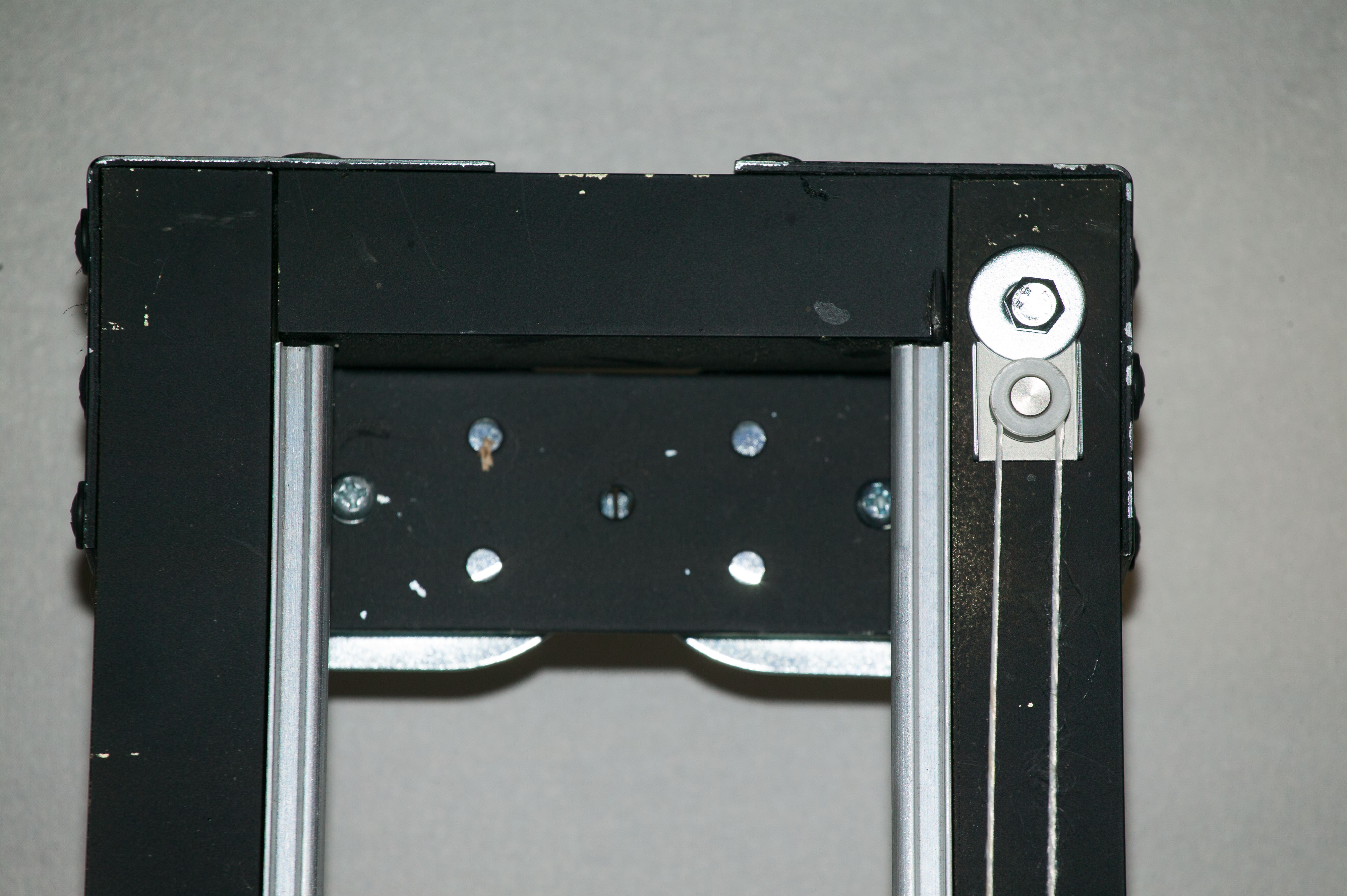
Alteration of the drive was over and I proceeded to mount it on the slider. Unfortunately, the photos of the manufacturing process of the slider itself died along with the hard drive, but I will try to show it clearly.
For assembly, we used a friend:
2 sets of Polish wheels on bearings for sliding wardrobes;
3 meters aluminum guides for sliding wardrobes;
4 steel angle 90 °;
4 meters square aluminum profile 2x2 cm;
3 strips for mounting the profile and 1 large for the carriage;
20-25 screws;
A can of black paint.
As a tripod head was twisted with a video clip head.

Wheel on guide (bottom view):


As a box for batteries, a box was used from the add. power for the player.


In full growth.

This is what a 45 ° camera slider looks like (sorry for the quality, taken from the phone):

Regarding the power of the servo: it was even more powerful than I expected. A camera with a lens and a flash on board is quietly raised on a practically vertically mounted slider.
Total
That's what happened in the end. The video accelerates at the end, as I unscrew the speed to the maximum. The plans still screwed to the tester timer, which will move the carriage after a specified period of time.
Thanks to everyone who helped me and without whose advice I could not do it. Especially Jura and svavan
UPD. As promised, he shot a movie with more weather in weather conditions. There was rain and strong wind on the street, so you can see the drops. Shutter speed of 1 second, between frames - 5 sec. f22 (since the ND filter has not yet acquired).
Source: https://habr.com/ru/post/209276/
All Articles