Traffic light on PLC - 30 blocks
Hello!
I want to show how to write a program for controlling technological equipment on a PLC.
Most often I dealt with Schneider Electric PLC. The selected Quantum for this task is the most powerful and expensive PLC of this manufacturer. It can control equipment with thousands of signals, for a traffic light in real life, no one, of course, will not use it.
I have never done automation of traffic lights, so I came up with the algorithm myself. Here he is:
1. Traffic light for adjustable pedestrian crossing. Those. a traffic light for cars, a traffic light for pedestrians and a button for pedestrians, by pressing which, the pedestrian notifies of the desire to cross the road.
2. After the program starts, the green lights for cars and red for pedestrians.
3. After pressing the button with the pedestrian, the green for the cars starts flashing, then the yellow one lights up, then the red one. After that, green for pedestrians lights up, after a set time it starts to flash, red for pedestrians lights up, then yellow and red lights up for cars, then green.
4. During a specified period of time after the green at a pedestrian traffic light, pressing the button with a pedestrian does not start the transition algorithm. In this case, the transition algorithm is launched only after a specified time has elapsed.
PLC programming is carried out in the Unity programming environment in the languages of the IEC 61131-3 standard. This standard includes 5 languages. For example, I chose the language of functional blocks - FBD.
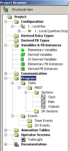
Here is the project browser in Unity:

Configuring PLC:

A PLC consists of a mounting panel, a power supply unit (1), a controller (2), a discrete input module for 32 24V DC signals (4), a discrete input module for 32 24V DC signals (5). In a real project, mounting plates connected to the same controller via different networks can have dozens, and I / O modules, hundreds.
Create variables of the required types in the variable editor:

Variables associated with the channels of the I / O modules have an address indicating to which basket, module and channel the signal is attached.
The program consists of sections performed in each scan cycle of the controller in order.
Simplified, the controller scan cycle looks like this:
1. Reading input signals from the input module to variables with addresses.
2. Execution of sections.
3. Write values from variables with addresses to output signals of output modules.
4. Go to paragraph 1.
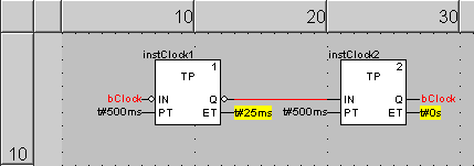
Create a Clock section with a pulse generator with a period of 0.5 seconds. TP block when the input signal changes from 0 to 1 at the output gives a pulse of a given duration.

Here and below, the screenshots of the sections are shown in the animation mode, not in the editing mode. They display the values of the variables at the current time when connected to the PLC with the loaded program (numbers for numeric variables, color green (1) -red (0) for Booleans).
The Main section handles the main logic.
The SR block sets the output to 1 when S1 = 1 and resets the output to 0 when R = 1.
The R_TRIG block sets the output to 1 scan cycle to 1 when the input transitions from 0 to 1 (a leading edge detector).
The F_TRIG block sets the output to 1 scan cycle to 1 when the input transitions from 1 to 0 (back edge detector).
The inButton variable tied to the button channel is replaced in the section with inButtonForTest so that its value can be changed on the controller simulator without real equipment.

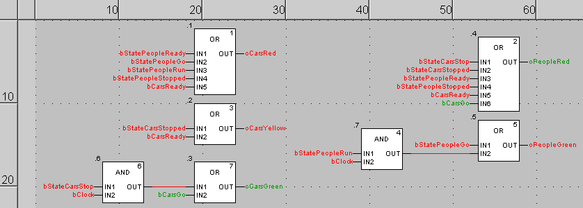
The Outputs section generates output signals for controlling traffic lights.

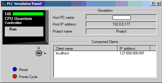
Download the project to the controller simulator:

The value of any variables can be viewed in the animation table:

But for debugging convenience, you can make an operator screen with simple graphics, the animation of which is tied to variables:

Trying to cross the road:
I did not expect that to control such a simple object as a traffic light, 30 blocks would be required.
In the next article I will show you how to write this program using all the languages of the IEC 61131-3 standard at the same time.
UPD. Fixed a mistake in the name of the standard.
I want to show how to write a program for controlling technological equipment on a PLC.
Most often I dealt with Schneider Electric PLC. The selected Quantum for this task is the most powerful and expensive PLC of this manufacturer. It can control equipment with thousands of signals, for a traffic light in real life, no one, of course, will not use it.
I have never done automation of traffic lights, so I came up with the algorithm myself. Here he is:
1. Traffic light for adjustable pedestrian crossing. Those. a traffic light for cars, a traffic light for pedestrians and a button for pedestrians, by pressing which, the pedestrian notifies of the desire to cross the road.
2. After the program starts, the green lights for cars and red for pedestrians.
3. After pressing the button with the pedestrian, the green for the cars starts flashing, then the yellow one lights up, then the red one. After that, green for pedestrians lights up, after a set time it starts to flash, red for pedestrians lights up, then yellow and red lights up for cars, then green.
4. During a specified period of time after the green at a pedestrian traffic light, pressing the button with a pedestrian does not start the transition algorithm. In this case, the transition algorithm is launched only after a specified time has elapsed.
PLC programming is carried out in the Unity programming environment in the languages of the IEC 61131-3 standard. This standard includes 5 languages. For example, I chose the language of functional blocks - FBD.
Here is the project browser in Unity:

Configuring PLC:

A PLC consists of a mounting panel, a power supply unit (1), a controller (2), a discrete input module for 32 24V DC signals (4), a discrete input module for 32 24V DC signals (5). In a real project, mounting plates connected to the same controller via different networks can have dozens, and I / O modules, hundreds.
Create variables of the required types in the variable editor:

Variables associated with the channels of the I / O modules have an address indicating to which basket, module and channel the signal is attached.
The program consists of sections performed in each scan cycle of the controller in order.
Simplified, the controller scan cycle looks like this:
1. Reading input signals from the input module to variables with addresses.
2. Execution of sections.
3. Write values from variables with addresses to output signals of output modules.
4. Go to paragraph 1.
Create a Clock section with a pulse generator with a period of 0.5 seconds. TP block when the input signal changes from 0 to 1 at the output gives a pulse of a given duration.

Here and below, the screenshots of the sections are shown in the animation mode, not in the editing mode. They display the values of the variables at the current time when connected to the PLC with the loaded program (numbers for numeric variables, color green (1) -red (0) for Booleans).
The Main section handles the main logic.
The SR block sets the output to 1 when S1 = 1 and resets the output to 0 when R = 1.
The R_TRIG block sets the output to 1 scan cycle to 1 when the input transitions from 0 to 1 (a leading edge detector).
The F_TRIG block sets the output to 1 scan cycle to 1 when the input transitions from 1 to 0 (back edge detector).
The inButton variable tied to the button channel is replaced in the section with inButtonForTest so that its value can be changed on the controller simulator without real equipment.

The Outputs section generates output signals for controlling traffic lights.

Download the project to the controller simulator:

The value of any variables can be viewed in the animation table:

But for debugging convenience, you can make an operator screen with simple graphics, the animation of which is tied to variables:

Trying to cross the road:
I did not expect that to control such a simple object as a traffic light, 30 blocks would be required.
In the next article I will show you how to write this program using all the languages of the IEC 61131-3 standard at the same time.
UPD. Fixed a mistake in the name of the standard.
')
Source: https://habr.com/ru/post/208560/
All Articles