The revived "moonwalker" or a toy, about which not all have heard
Today I would like to tell you about the programmable self-propelled moon rover as written on it. The fact that such a toy existed, I knew only by hearsay - a friend told me that in childhood he had a similar one. Appearance is presented in Figure 1.
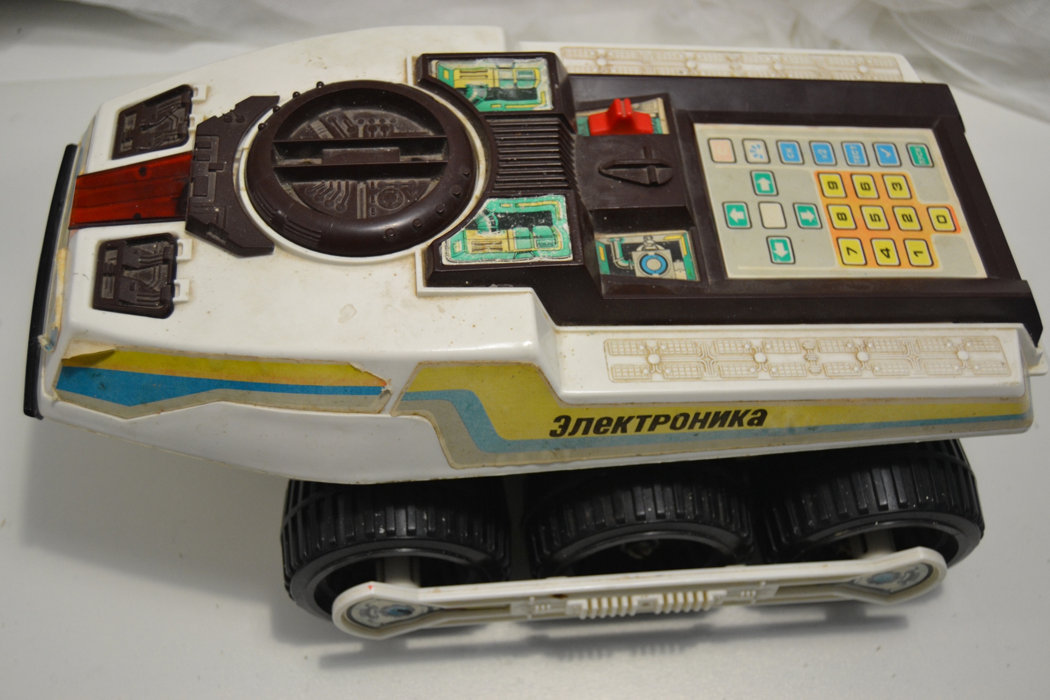
Fig. 1 Appearance moon rover
All interested in asking under the cat, which will be told the story of dating and return of the Lunokhod to life. Carefully, there are a lot of photos under the cut.
By the will of fate, he was given the opportunity to work as a teacher in theIvanovo State Textile Academy, Ivanovo State Pedagogical University. One fine day, my then still student, and now graduate student Sergey Bazhenov, brought this miracle of technology, since at the department we are engaged in various works in this area. I immediately realized that this is exactly the robot that my friend mentioned (as it turned out later, it really was him). Robot Sergey, too, someone gave, with the words that he is fully operational. Appearance gave hope that it really starts without problems. Front view is shown in Fig. 2
')
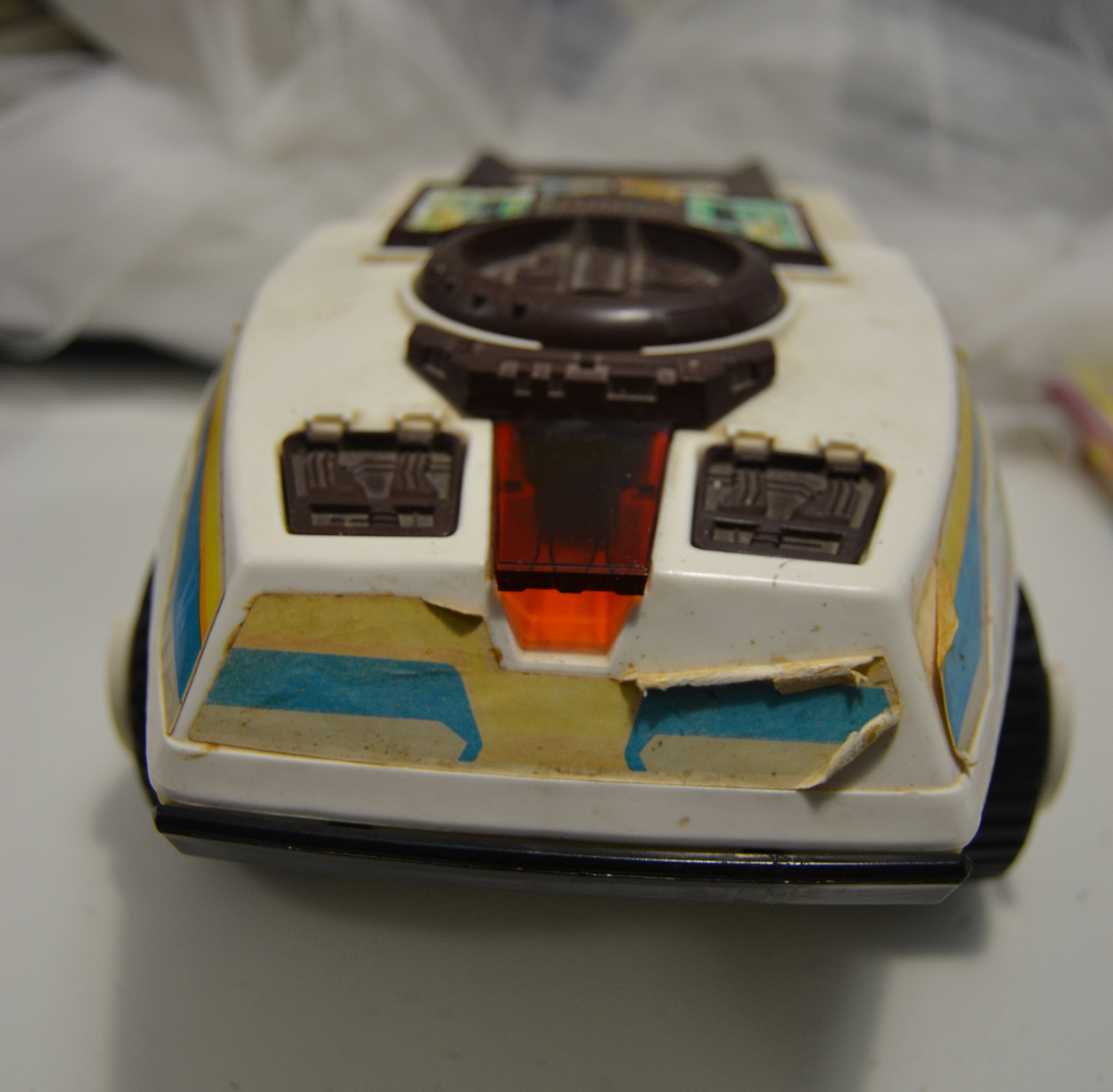
Fig. 2 front view
Inspection showed that this model of the Moon Rover is a programmable self-propelled ELECTRONICS Factory number 476, already released in November 1986, the price is 27 rubles (Figure 3).
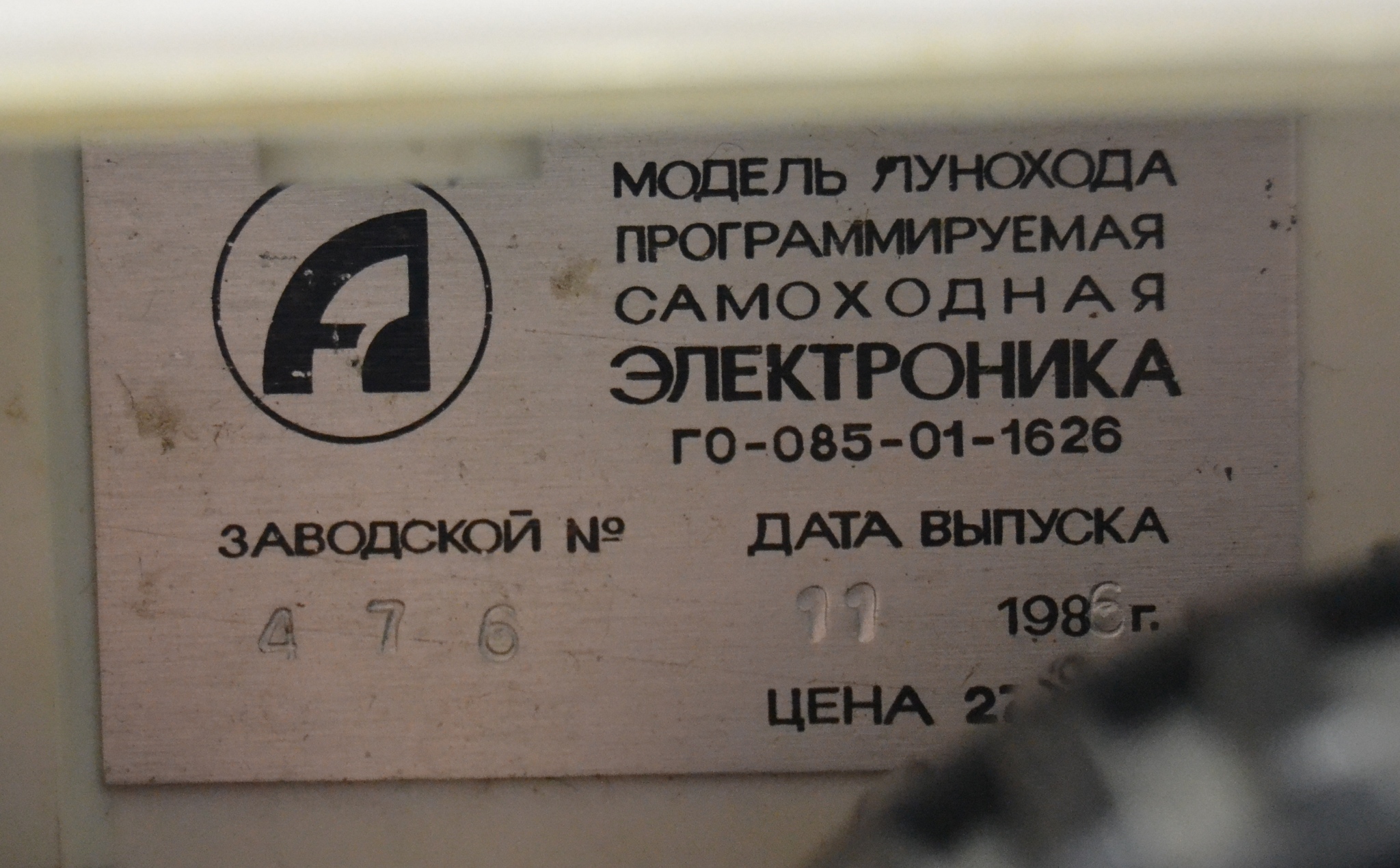
Fig. 3 information tag
From this information, I personally experienced a little shock - have we developed such a miracle? However, a small search brought a slight disappointment, it is a clone of the BigTrak toy.
However, his desire to launch it did not diminish. Batteries were purchased, installed in the compartment ... (Fig. 4) and a slight disappointment awaited us, the robot did not respond to any operations.
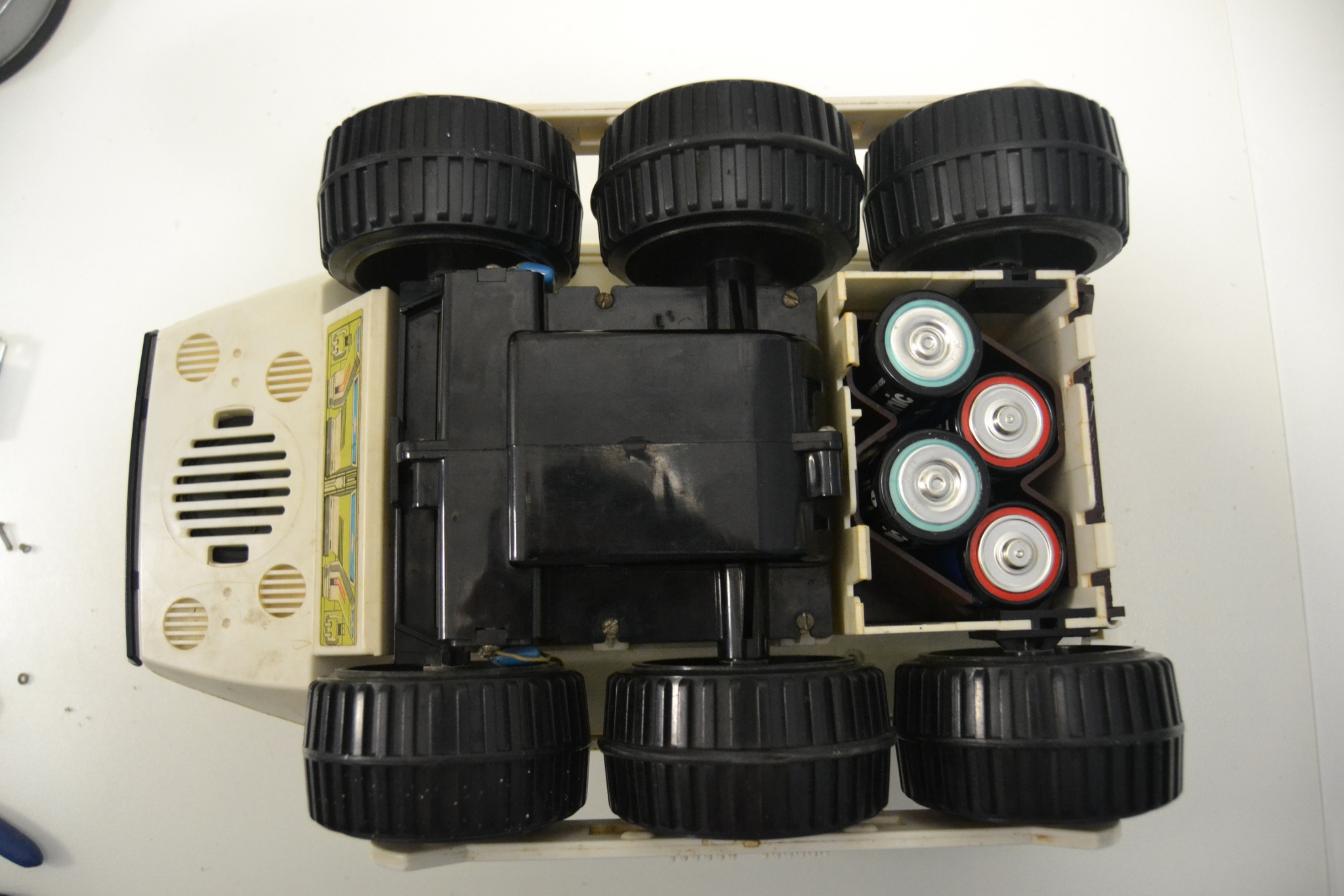
Fig. 4 Battery compartment
It turned out that we had forgotten another place to install a crown-type battery to power the device board (Fig. 5).
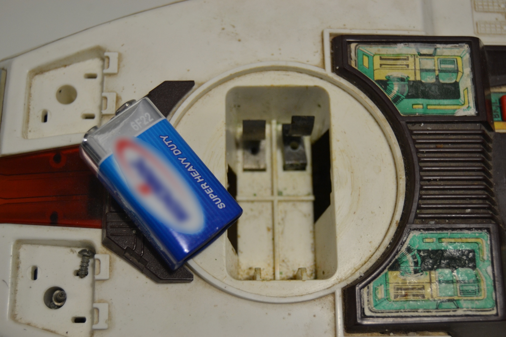
Fig. 5 Compartment for the installation of "crown"
However, this did not help, the contacts were strongly oxidized, and the opening of the case also revealed several wiring torn off from the board (Fig. 6) (one was definitely, another patient probably got after opening).
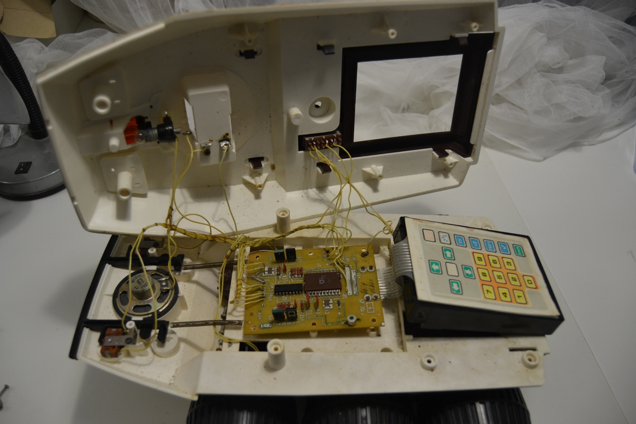
Fig. 6 Internal lunar rover
The photograph of the opened robot (Fig. 6) clearly shows its device. On the left (in Fig. 6) there is a black bumper located at the front, connected to microswitches which made it possible to turn off the toy when it hits an obstacle. There is also a speaker located above the light bulb. In the center is the control unit (Fig. 7).
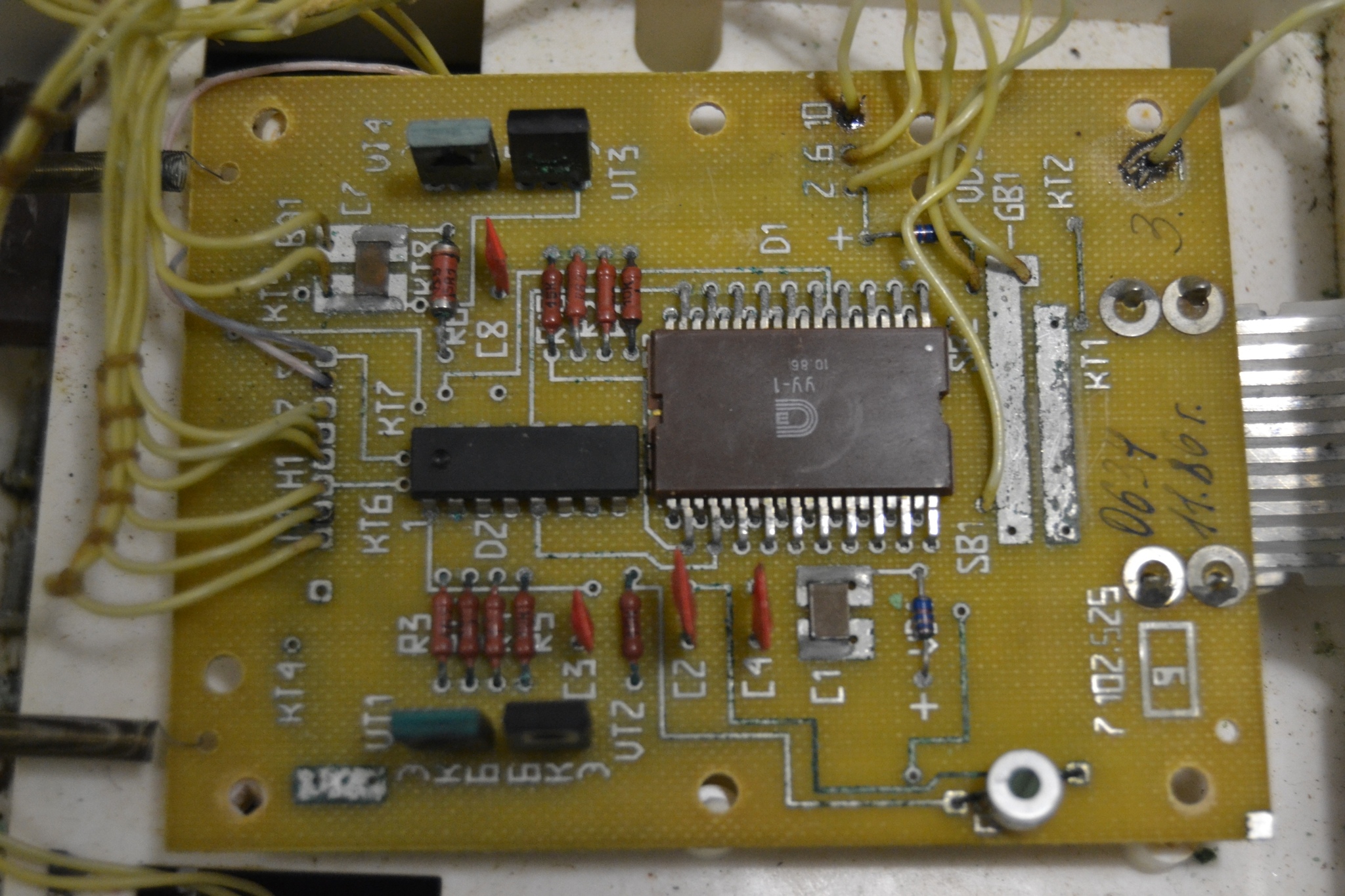
Fig. 7 control unit
In the back (in Fig. 7 on the right) there is a keyboard for programming commands to the robot. Under the keyboard is a block with batteries (Fig. 8).
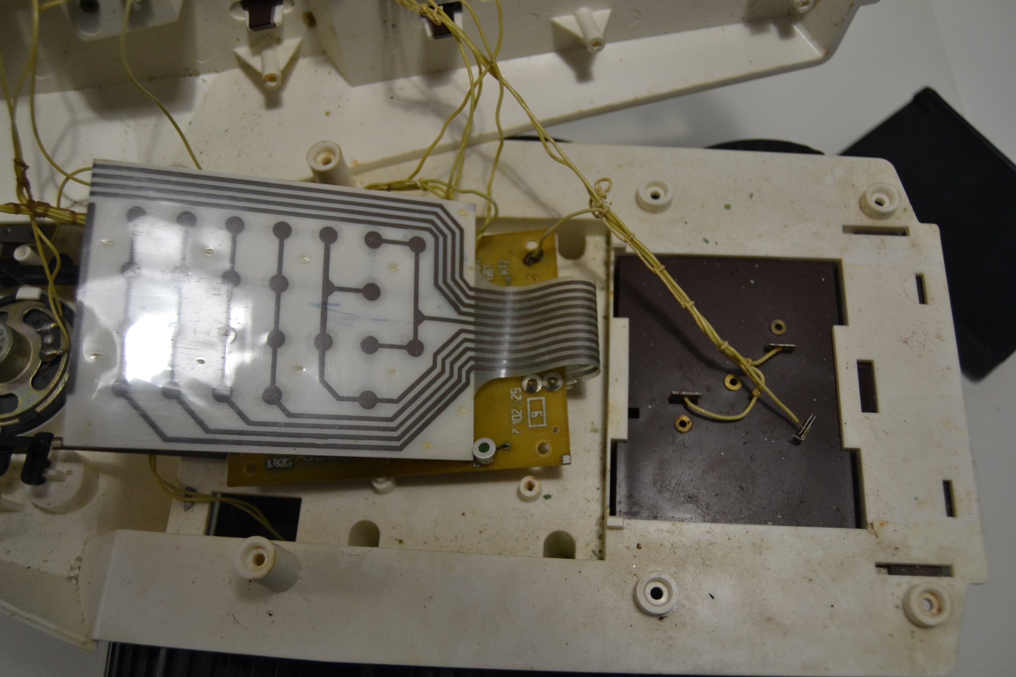
Fig. 8 Photos with flip down keyboard
After the opening, a sufficiently large amount of time passed, during which two desires struggled inside - to install the Raspberry Pi and Arduino and completely upgrade the robot and the desire to preserve the original beauty of the model. In the end, won the desire to leave him as a memory in the form in which he came to us, only to restore its performance.
And now, on this long weekend, time was allotted for recovery. The loose wires were back soldered, the oxidized contacts cleaned. And about a miracle - the device came to life, after clicking on the "Test" button, it sounded and not just sounded, but drove off, although with one right-hand wheel. After a small push, the left also moved. I had to go to the opening of the drive, the benefit of maintainability is at a height (like many other Soviet products, which had to face) (Figure 9-12).
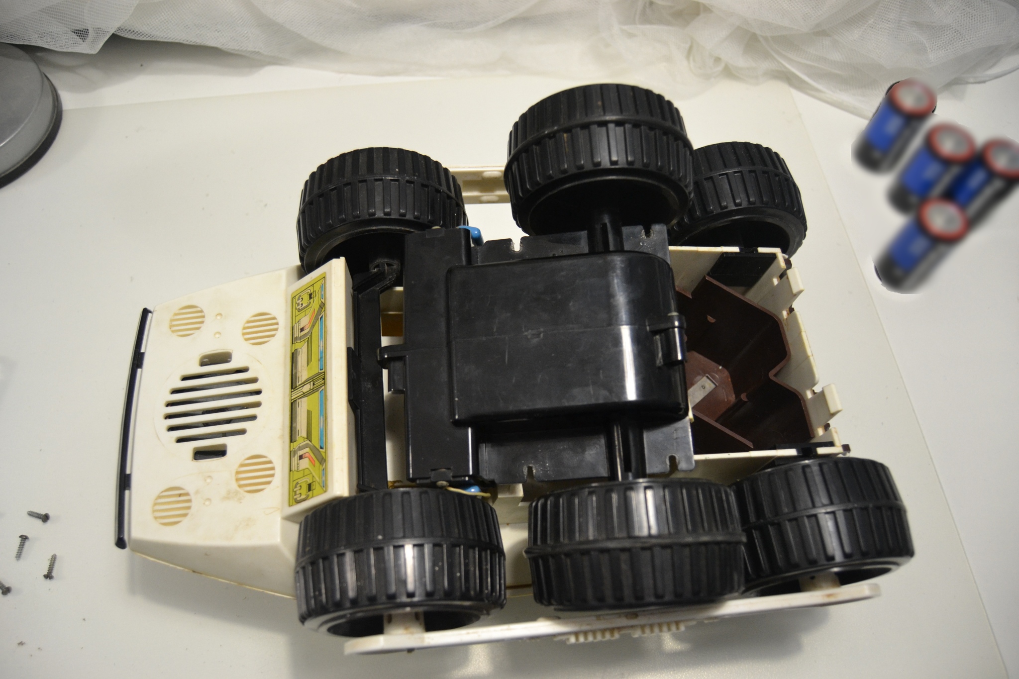
Fig. 9 Bottom view with the drive disconnected
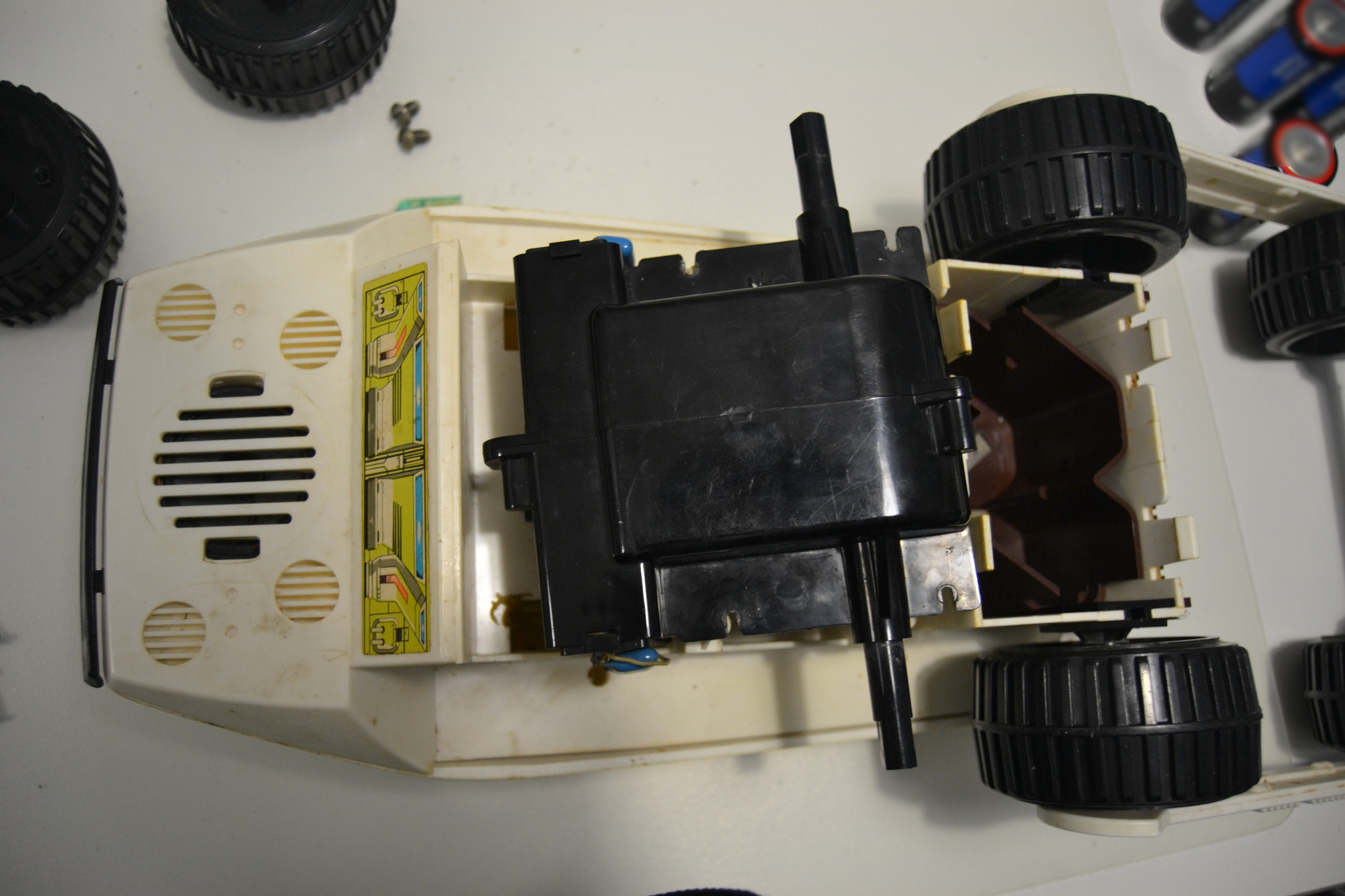
Fig. 10 Drive before opening
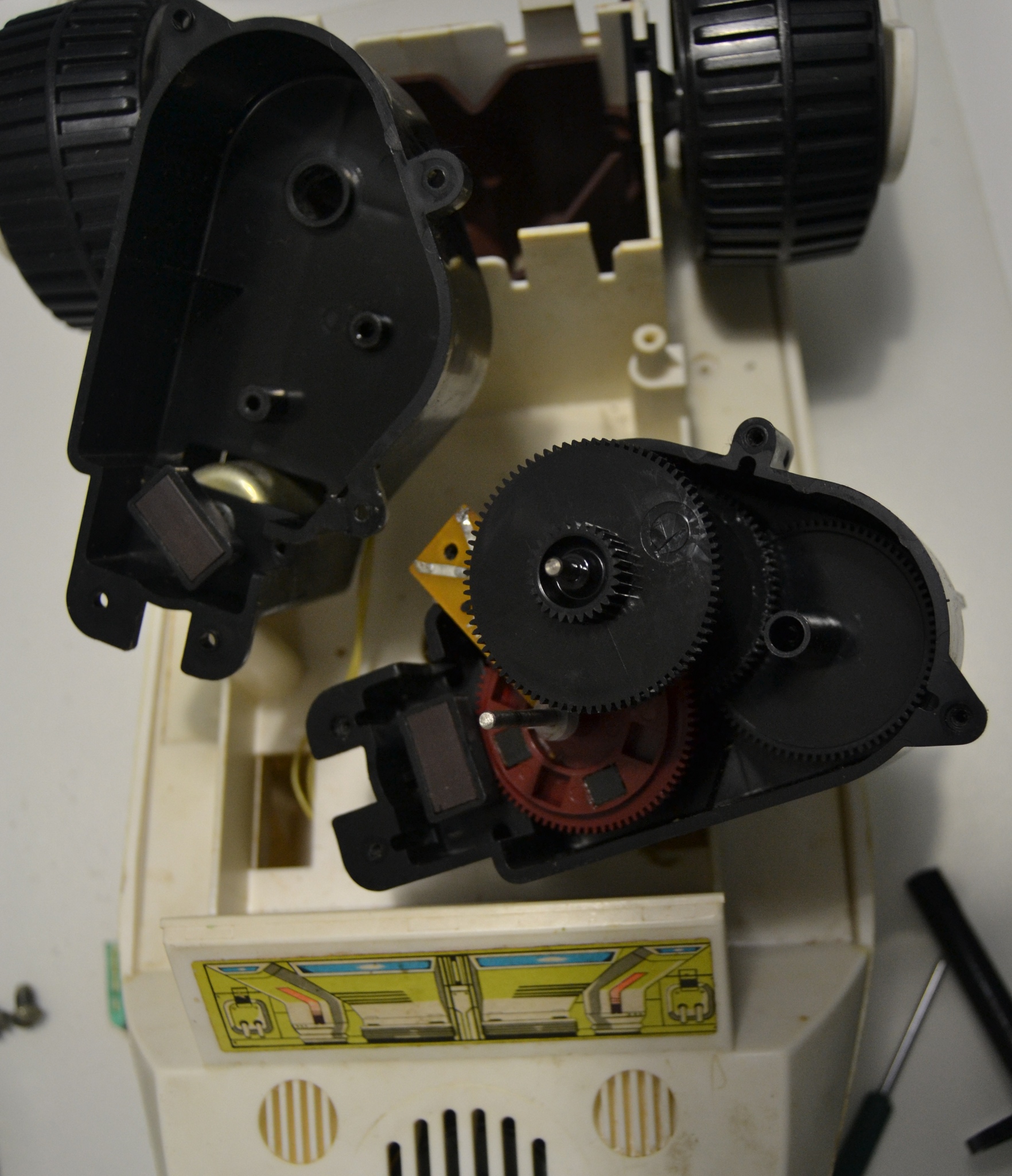
Fig. 11 Appearance of the drive unit
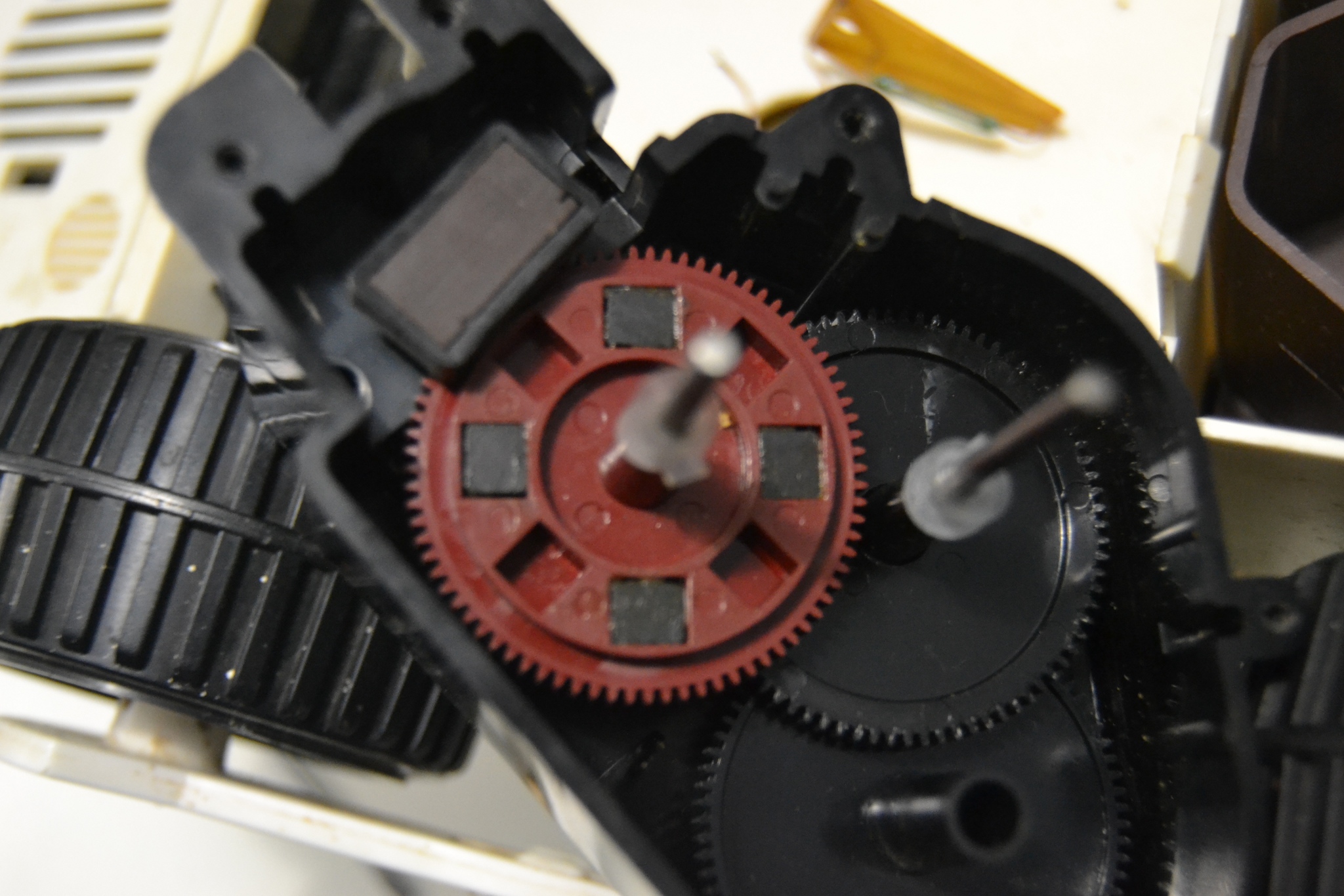
Fig. 12 Right engine block
Opening the drive unit (Fig. 11-12) showed an interesting scheme for determining the distance traveled. Several magnets are installed in one of the gears (Fig. 12, the red gear), and the reed switch is installed nearby (you can see the reed switch and the cut off contact in Fig. 13). To synchronize the revolutions of both gears in the straight-line motion on the shaft of both motors there are rectangular magnets (for the right divgatel shown in Fig. 12 on the left).
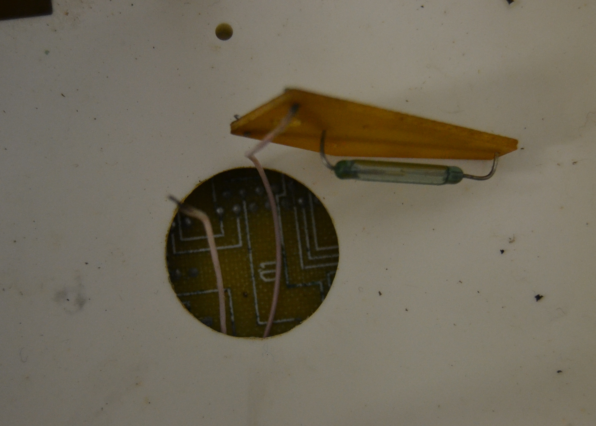
Fig. 13 reed switch
Unfortunately, an autopsy showed that in several places the gears of the left wheel had broken teeth. However, now the robot is fully functioning, as evidenced by the video below.
A small review showed that today, our eternal friends are producing the BigTrak Chinese (wherever without them).
Moreover, there is a reincarnation of BigTrack and a new version with a camera and control through the phone.
Work on the restoration of the lunar rover will be continued together with the students (it is necessary to replace the gear, check the contacts coming from the reed switch), and it will take its honored place in the department ofsystem analysis of land transport and technical systems.
Fig. 1 Appearance moon rover
All interested in asking under the cat, which will be told the story of dating and return of the Lunokhod to life. Carefully, there are a lot of photos under the cut.
By the will of fate, he was given the opportunity to work as a teacher in the
')
Fig. 2 front view
Inspection showed that this model of the Moon Rover is a programmable self-propelled ELECTRONICS Factory number 476, already released in November 1986, the price is 27 rubles (Figure 3).
Fig. 3 information tag
From this information, I personally experienced a little shock - have we developed such a miracle? However, a small search brought a slight disappointment, it is a clone of the BigTrak toy.
However, his desire to launch it did not diminish. Batteries were purchased, installed in the compartment ... (Fig. 4) and a slight disappointment awaited us, the robot did not respond to any operations.
Fig. 4 Battery compartment
It turned out that we had forgotten another place to install a crown-type battery to power the device board (Fig. 5).
Fig. 5 Compartment for the installation of "crown"
However, this did not help, the contacts were strongly oxidized, and the opening of the case also revealed several wiring torn off from the board (Fig. 6) (one was definitely, another patient probably got after opening).
Fig. 6 Internal lunar rover
The photograph of the opened robot (Fig. 6) clearly shows its device. On the left (in Fig. 6) there is a black bumper located at the front, connected to microswitches which made it possible to turn off the toy when it hits an obstacle. There is also a speaker located above the light bulb. In the center is the control unit (Fig. 7).
Fig. 7 control unit
In the back (in Fig. 7 on the right) there is a keyboard for programming commands to the robot. Under the keyboard is a block with batteries (Fig. 8).
Fig. 8 Photos with flip down keyboard
After the opening, a sufficiently large amount of time passed, during which two desires struggled inside - to install the Raspberry Pi and Arduino and completely upgrade the robot and the desire to preserve the original beauty of the model. In the end, won the desire to leave him as a memory in the form in which he came to us, only to restore its performance.
And now, on this long weekend, time was allotted for recovery. The loose wires were back soldered, the oxidized contacts cleaned. And about a miracle - the device came to life, after clicking on the "Test" button, it sounded and not just sounded, but drove off, although with one right-hand wheel. After a small push, the left also moved. I had to go to the opening of the drive, the benefit of maintainability is at a height (like many other Soviet products, which had to face) (Figure 9-12).
Fig. 9 Bottom view with the drive disconnected
Fig. 10 Drive before opening
Fig. 11 Appearance of the drive unit
Fig. 12 Right engine block
Opening the drive unit (Fig. 11-12) showed an interesting scheme for determining the distance traveled. Several magnets are installed in one of the gears (Fig. 12, the red gear), and the reed switch is installed nearby (you can see the reed switch and the cut off contact in Fig. 13). To synchronize the revolutions of both gears in the straight-line motion on the shaft of both motors there are rectangular magnets (for the right divgatel shown in Fig. 12 on the left).
Fig. 13 reed switch
Unfortunately, an autopsy showed that in several places the gears of the left wheel had broken teeth. However, now the robot is fully functioning, as evidenced by the video below.
A small review showed that today, our eternal friends are producing the BigTrak Chinese (wherever without them).
Moreover, there is a reincarnation of BigTrack and a new version with a camera and control through the phone.
Work on the restoration of the lunar rover will be continued together with the students (it is necessary to replace the gear, check the contacts coming from the reed switch), and it will take its honored place in the department of
Source: https://habr.com/ru/post/208450/
All Articles