Welding of optical fibers. Part 3: review of the wiring connection schemes, review of network construction schemes, a little about reflectometers and optical testers

Input control drums with optical cable
Hello! I post the third part of my story about working with optical fiber. In this part, I will, to the best of my knowledge, tell you about the wiring of optical couplings and how to work with them, about optical network diagrams with examples, and also introduce you to devices for optical measurements (optical reflectometer and optical tester). In the third part I planned to tell everything about measurements, but the topic of measurements is quite large, plus I found it necessary to better clarify the wiring for the sleeves and the construction of networks, and the article is too long. So there will soon be another part about setting the OTDR and reflectogram analysis.
First part here
Second part here
')
Caution traffic!
Soldering schemes
In the last part, we welded the optical coupling (or cross), but I did not dwell on the instructions on which the coupling should be soldered. Indeed, it is far from always that the couplings are soldered straight: often they are tee ((), that is, for 3 cables, or even for more cables. And I know for myself that it is not easy to weld a complicated coupling according to a scheme without experience.
For clarity, it should be noted that the T-shaped connection of two optical fibers in the general case does not happen, the fibers are always fused in pairs. A tee, "Quad" and other compounds are found in PON networks and in television via fiber, but this separation is carried out by a special splitter, manufactured at the factory. It has 1 input and several outputs: a relatively powerful signal is fed to the input, it is divided into outputs in a passive way, and these outputs are connected to subscriber fibers, for example, to apartments. But to make such a connection using a welding machine is impossible.
How does the T-shaped connection of cables in the coupling at the level of cables is carried out, and at the level of fibers is not carried out? Below we will look at it.
It should also be noted that the desoldering schemes are drawn differently. If we take the standard, then such a scheme is defined by the document “FOCL PT-6” (included in the executive documentation for the object, in the book “Passport of the route”). However, each spider / designer draws these schemes as he wants. And since we know that something simple and logical for one person can be incomprehensible and confusing for another, sometimes it is inconvenient to understand someone else's scheme.
Sometimes these schemes are made colored: on modules and fibers, they do not just write that they are red and green, but also color them appropriately. Sometimes they do not even sign at all what color the fiber is. Plus the fact that it is so clearer, less stress on the attention of the solder when unwinding, the scheme looks much more solid. Minus - if this scheme is printed out for the driver on a black-and-white laser printer (which often happens), then yellow, light green and other bright lines can be seen very badly. And if the colors are not yet signed with words, in general the work will arise. And it will be still good tone if you put through numbering of all the fibers.
I took for example a few mixed diagrams in order of complexity: some of them were used in my work, some were pulled from the Internet.
1) To begin with, we will consider the wiring method for a straight coupling, where both cables are the same - this is the easiest option. This scheme is found on the expanses of the English-language Internet.
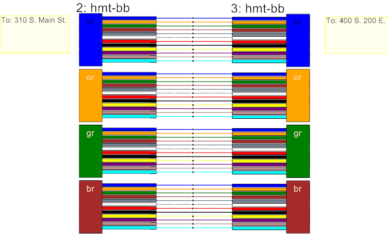
Here, as we see, there is nothing complicated: in each of the cables there are 4 modules of 12 fibers, all you need to do is 48 welding. Everything is brewed in color — blue fiber from the first blue module of the first cable — with the blue fiber of the blue module of the second cable, orange with orange, and so on. If it is known that the clutch is straight - you can do without a scheme. Although for reporting the scheme is still necessary to draw.
The main thing is not to cross over modules by mistake!
As for the layout of the welded fibers on the cassettes, I wrote about this in the last article: you need to think in advance about which groups of fibers on which lodgment of which cassette will lay down and measure the fibers accordingly before welding. Algorithmize this for complex couplings, I think, is unrealistic; you just need to look at the situation, what kind of coupling we have, how many fibers and how rational to place them. As for the example from the image above, then, depending on which coupling we have with which cassettes, I would distribute the fibers like this:
a) If we have a compact coupling with small cassettes of 12 places for KDZS, then it is obvious that the fibers from the blue modules will lay down on the first cassette, from the orange ones - on the second, etc. By the way, you can also weld the coupling from the end, then on the first (lowest) cassette there will be a brown module. So it will be more logical: the first fibers are on top, the last ones are on bottom. But it is at the discretion of the solder.
b) If we have cassettes of 32 fibers each, it is logical to weld the first 2 modules (12 + 12 fibers) on the first cassette, the third and the fourth (12 + 12) on the second. Yes, at the same time in each cassette there will be 8 free places, which theoretically could be useful if something is welded into the clutch. Of course, it would be great if one cassette was completely filled, and in the second one there are 16 free places left. At the same time, the KDZS from a hypothetical welding cable will be located side by side, all together, on one cassette, and not split into two cassettes. But in this case, we will have to divide the second module into 2 cassettes and to do this, make a transition tube, which is inconvenient. Better still, do not put the adapter tube and cook 12 + 12 on the first cassette and 12 + 12 on the second one.
c) If there are cassettes for 36 fibers, then again we will need 2 cassettes, and again we can do it in different ways. We can either take each part partially (24 places out of 36), or in the first one we boil 3 modules, and in the second - the 4th. I personally would choose the second option: we do not need to fence transition tubes (12 + 12 + 12 = 36, the cassette is fully occupied), and we have 24 places in the second cassette.
In a similarly simple way, like unwelding a straight coupling, the scheme of soldering the cross looks like (if only it is simply a cross and there are no transit welded fibers). The cross is even simpler: the fibers need to be measured on one side only, and the pigtails can be folded into rings inside the cross (keeping bending radii) and fixed on the internal surface of the cross without winding them into a cassette. By the way: for fixing pig-tails inside the cross, so that they do not dangle, such plastic fasteners serve here. It is usually bundled with many crosses. Although if it is not, you can glue with tape or tape.
Fastener
2) The next variant of the decoupling scheme is the same scheme as last time, only the colors of the modules and fibers differ (but the number of fibers in each module is the same, say, 12). The drawing of the scheme does not make sense. This will not affect the layout of the fibers on the cassette, but attention will have to be turned on when working! Before each welding, you need to check the scheme, checking that - yes, indeed,
[thirteenth blue fiber from the second blue module of the first cable {MarkCabel1, direction1}]
brewed on
[the thirteenth red fiber of the second green cable module {MarkCabel2, direction2}].
By the way: if it so happens that unused fibers remain (according to the scheme) with any of the cables, they should not be cut off in any case! They need to be put in a cassette, even without measuring. In the future, they may be involved (when upgrading the network or if some of the fibers in the cable are damaged), and the joiner, who then gets into the coupling to weld to these fibers and finds them cut off at the root, will be very “happy” from the prospect of a complete reworking of the coupling
3) The following example is a straight coupling for 2 cables, which differ in the colors of the fibers and the number of fibers in the modules. I did not immediately find the suitable “beautiful” scheme, so I drew my very, very similar to what I often worked with, quickly in Paint. For clarity, I painted everything with colors (colors from the noodle), but usually they don’t bother like that and just sign the colors abbreviated.

Here, as you can see, the modules and the fibers do not fit in a beautiful way, they are inconsistent. Yes, I do not like cables with a non-constant amount of fibers in the module (like the left one on my circuit), because they introduce asymmetry and inconvenience, but nevertheless, such cables often come across and need to be cooked.
As before, we take 2 cassettes for 32 (36) fibers, but now we will need to transfer some of the fibers from one of the modules to the second cassette through the adapter tube. Most likely, module 4 will be split on the cable to the left (then the number of welds is divided equally between cassettes), respectively, green, brown, blue and pink fibers from the 3rd blue module will go from the first cassette to the second one. But according to circumstances, the 3rd module of the right cable can also be divided. It is highly advisable to sign where the fibers are: I usually sign with a thin alcohol marker (which is for a CD) right on the cassette, where it goes. Also, during splicing, temporary tags can be hung on the fiber groups (made of paper with an inscription in pencil and a piece of scotch) so as not to forget which fibers go where. And most importantly - you need to include attention in order to avoid a mistake when unpacking! Such a clutch, despite the fact that it is direct, can pull the nerves of a newcomer. For convenience, you can mark on the diagram with a pencil what is already cooked and what is not, so as not to get confused.
4) The next clutch, which we consider - is a simple "tee", it is also a "push-in clutch", it is also "branching". Let's take a picture - well, let's say, from the example of filling in the form of fiber optic PT-6.
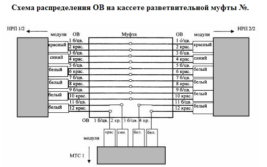
We see that most of the fibers are unsoldered in transit, and 2 fibers from each 12-fiber cable (coming from the IUU 1/2 (Unattended Regentation Point) and leaving the IUU 2/2) are boiled soft to a “tap-off” 4-fiber cable (which went to the MTS 1). Although it may be that the cable on the left will not be connected to the cable on the right, and the entire left cable will go to the “left” half of the bottom, and the entire right - to the “right” half (suppose it has not 4 fibers, but 24) .
This is how the tee is implemented on optics. Here, seal off as if bilateral, that is, 2 fibers are soldered, 2 are back. Or maybe “one-sided”, when 2 fibers left for unsolder, but did not return and the remaining fibers remain unused. There may be many options to feel - you need to "feel" yourself.
With the help of such couplings, the connection is diverted from the main line to intermediate points. And it is precisely with the help of such snap-on couplings that rings are built, for example, FTTB: the switch has both Fast / Gigabit Ethernet subscriber ports and trunk ports for GBIC / SFP / XFP / other modules. Here are two otpaivayuschih fiber (through a cross connection) are connected to the same port XFP (1 module usually 2 sockets standard LC), and from the second port two fibers are returned to the cable. And so these 2 fibers from the cable (in our example, the 11th and 12th) dive from house to house, from the switch to the switch, respectively, the switches pass through these ports both their own traffic and other switches. Well, and then the ring is closed, the cable returns to the node where the ring started from, and the main optics are right there. The ring is needed for redundancy: if the cable is broken, the traffic will go along another half ring. And the rest of the fibers that go in transit can be used for a separate television network (then one more cable is cut off for each house), or in the future for other needs. About this network architecture, see a little below.
5) Here is a little more sophisticated otpaynaya coupling. Again, almost all the fibers from the lower cable go to the upper transit, but some of the fourth modules are otpaivatsya on the cable, which is on the left. Or the cable on the left is partially welded into the trunk - so to speak.
In this case, of the 32 fibers of the “push-off” cable, only the first module (8 fibers) is welded into the 48-fiber trunk. But it may be more, and not one “bunch”, as it is here, but in several small groups, which complicates the work very much.
How to distribute such fibers in cassettes? It usually makes sense to first weld all the straight fibers, and then unsolder, and take it separately, preferably in the upper cassette. And be sure to sign where the module is and where it’s off. In general, again, you need to think and look at the configuration of the available tapes. If it happens that you can do without the adapter tube, but at the same time some of the cassettes have extra 2-4 fibers, for which there is no regular place - I allow myself to stick them securely on electrical tape or sealant and press them with the next cassette, as I consider , that it is a lesser sin than to mold a transition tube without a strong need: the transition tubes greatly inhibit the work and complicate access to the cassettes. Although it may be wrong.
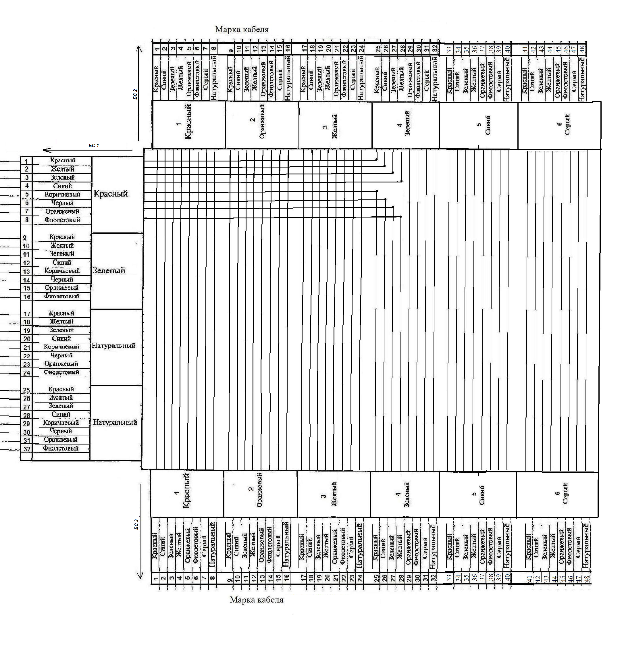
6) And finally, we consider a relatively complex coupling, where there are a lot of cables and a bunch of fiber groups that are being cut off in all directions.
We see that there are not so many welds (30), but there are as many as 5 cables. In such a clutch is already easy to get confused! It requires a lot of effort and splitting, and subsequent maintenance. And it happens even worse, much worse when all the cables are different with different colors, with different number of modules, when there are many small taps from one cable to another (sometimes even an odd number of fibers are soldered), when there are a hundred or more welds and It turns out a high stack of cassettes. I would show, but did not find a suitable scheme. Imagine how awful and solder such a solder without error, and then serve? So it is better to avoid designing such couplings in the network: there will be less headache for both solders, operators, and service organization. Some managers responsible for their network are firmly committed to not inserting more than 3 cables into the coupling, they say, if necessary, place another coupling next to it. Of course, sometimes clutches for 4-5 + cables cannot be avoided. In this case, such couplings should be taken only with a fresh mind, and you should definitely sign and label everything. If it is very hard - you can cook one fiber at a time: take a couple of fibers, figure out where you put it, measure it, cook it, put it in place. Then he took the next pair. It will be very long, but the work will be done, but with experience, the speed and “operational memory” in the head will increase.
Network diagrams
We have reviewed examples of schemes for which individual couplings are soldered. But for each object, a common unified scheme is also compiled, in which all the schemes of individual couplings and crosses are combined into a single network (a form of fiber optic PT-8). This can be an FTTx ring, a ring, a cellular network binder or police stations, a tree network, a “star”, or just a long line between cities, with their own unsolder. Or maybe a ring linking cities and countries! Or the PON / GPON network, which I have not yet encountered. Or exotic type FDDI (development of Token Ring'a for optics).
Such a scheme can take a huge drawing paper, is drawn using CAD software and requires a lot of work to create. Unfortunately, I do not have suitable examples to show, and I have no right to publish those that exist. But I think it is clear what is at stake. Designing such a network is the work of communications designers, so I don’t feel like a good specialist in network topologies, I don’t know how to design such a network in the most rational way and I cannot give them a high-quality and complete classification. The design takes into account such moments as: what equipment will stand there, how many ports do you need, how to make redundancy and at the same time save on the number of future couplings and the amount of welds needed, how to make the network simple and not design clutch monsters, do you need a cable with displaced dispersion, what actually happens at the place of our future construction, will our equipment stand there (you need to go all the way and see / take a photo) and more. etc. Although I met experienced solders who could go and write out a more or less rational and working draft of a rather big network for a customer who didn’t bother to think about what he wanted to build and order the project to the designer. This is possible because an experienced solder, who has worked for many years and has soldered dozens of objects, knows by heart all the typical solutions and typical equipment used. And yet if the programmer often has to pull out at the customer what he wants, and then program, then for the signalman, this is not a very typical situation.
But I will tell you a little about these schemes. Maybe, even in those schemes that I quickly sketched in Paint and quoted below, I made inaccuracies. =) Perhaps, someone else will tell about it more qualitatively by writing a corresponding post. And I will show only rough "examples" so that the reader has a general idea of how it works.
I have met the topologies “ring”, “tree”, “line with unsolder” and all their modifications.
What is a line with unsolder? Nothing complicated: there is a trunk cable, in it (as in the same modules and fibers), according to a typical scheme, the spliced cables are welded in some places (according to the above scheme of the desoldering coupling). A separately constructed line can then be combined with other lines of the same provider, closing them all into a ring.
What is a tree topology? From the data center (server provider, PBX, LAZ, base station etc) comes a thick cable (“root”), say, for 96 fibers. Soon it is split in half into 2 * 48 (using a tee coupler), each half is still divided in half, further more and more, and the "crown" of the tree weaves a part of the microdistrict; a switch (or a pair of fibers) comes to every house in the switchboard . If in the above “line with unsolder” each time different fibers and modules are soldered off, this will also be a “tree”. Cable consumption is small, instead of expensive switches, you can put a cheap ethernet media converter on each house, but all the coupling schemes are unique, there are no typical ones, and in case of cable breaks, some houses will fall off for a long time. I met this in the neighborhood, where there are many scattered five-story buildings and the ring is inconvenient to do.
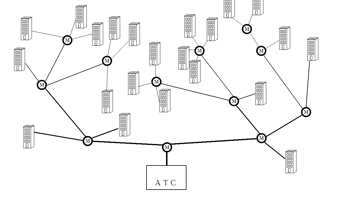
And what is the ring topology?In one of the variants, the cable bypasses all points in turn, “diving” with a part of its fibers (red and blue by example) to each house / BS / server / etc (through the ) on the switches, and eventually returns to where it came from. At each point there are switches that can pass transit traffic.
Part of the fibers (green in my example) can not dive anywhere, but be used for measurements, to come to the main crosses, to quickly determine where this time the jamshuts broke off the cable, rather than running from house to house and not measuring pieces from house to house, calculating distances. I also drew this variant on the scheme. Or, it is better to go in as well as working fibers to each house, but to go through the patchcords with “transit”, without putting up with the equipment. Or this: the first two fibers carry the Internet and dive from house to house, and the rest serve for a separate television network (if the television does not go through IP): the third fiber “dives” to the first house, the fourth to the second and so on. It may be that in the ring there is not 1 main station with two trunk crosses, where the cable came from and where it came, but 2-3 and more,then through the "main" fibers there will be a transit connection between these stations.
There may be many options. I brought what I worked with and what I consider to be the most obvious and simple way to build a “ring”. Probably, there are more rational and advanced schemes, as there are more sophisticated ones, where the beginner will not understand the move.

Such a scheme is more expensive than a tree, since it requires more cable and work and serious transit switches, but if the cable is broken, the network will be able to work on the remaining half ring.
This I have met where there are many compact five, nine and other high-rise buildings.
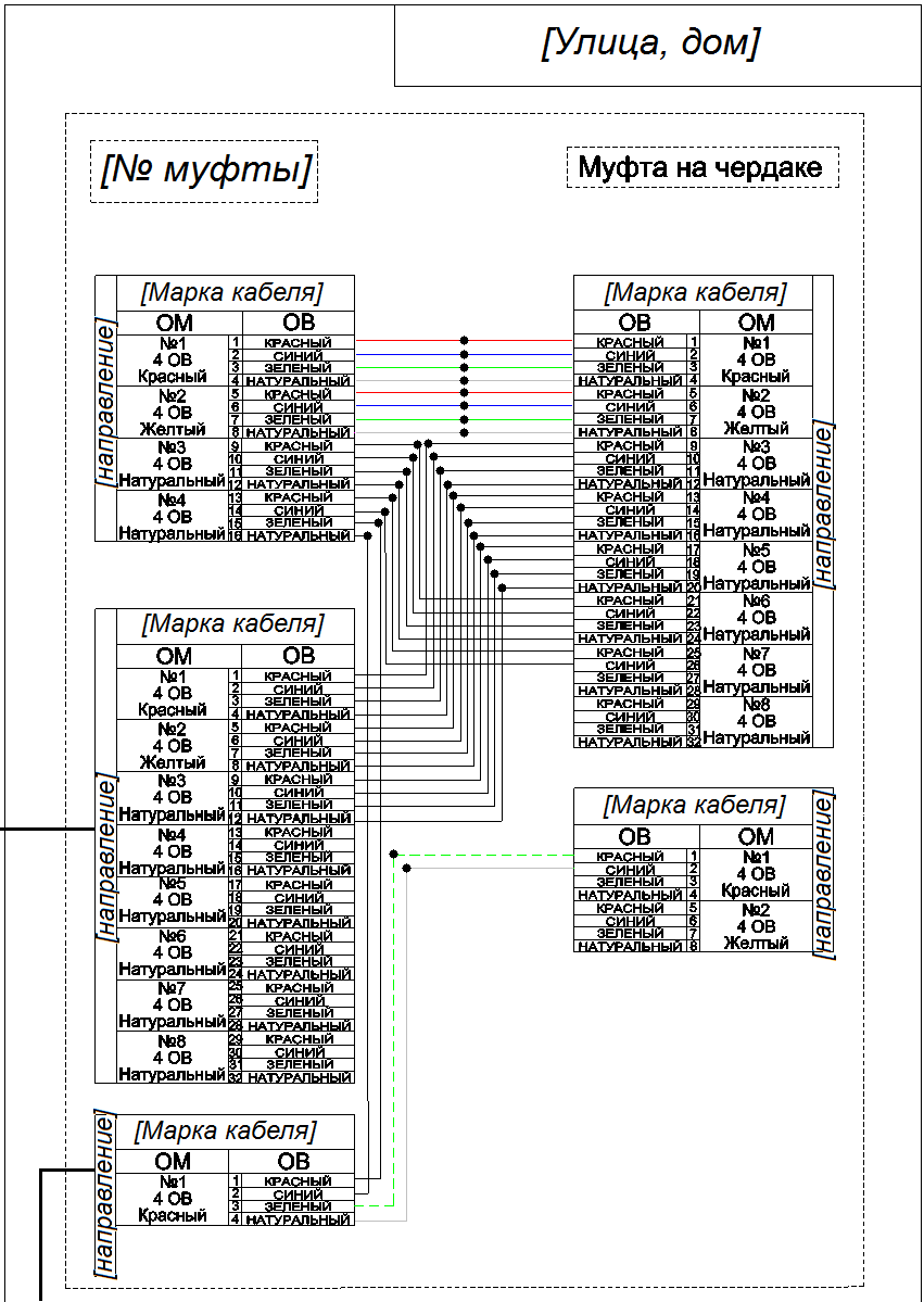
Here is another interesting picture. This is a small fragment of another scheme that we soldered. In this case, not 1, but 2 straight-off cables are immediately removed from the coupling (obviously, the houses are long - on 6+ entrances, and the disconnected cables come to crosses installed in the 2nd and 5th entrances, so that nowhere is the length of the twisted pair from the equipment box to apartments did not exceed 100 m). Plus, one fiber is “lowered” to each house (more precisely, two - from different sides of the reservation ring) for a separate television system. As you can see, only the numbers of the fibers are marked, and the colors are not indicated: it is inconvenient, you need to have in addition to the scheme also passports of two types of cable (desoldering and main) and when you unwelding, check all the time what color, say, 5th or 21st fiber The scheme is working, so that with the handle we unwind for convenience, we noted that it was already welded.I painted the addresses of the houses, just in case.

We see that the Internet comes to each house with two fibers (1 and 2 from the “ring” cable, through the fibers 1 and 2 of the desoldering cable to 1 and 2 ports of the cross), and goes to the 4 and 5 ports, through the fibers 5 and 6 of the desoldering cable, again on fibers 1 and 2 of the "ring" cable. That is, from the “ring” cable, only the first 2 fibers are needed for the Internet, and all the rest are for television, which is divorced according to the principle “1 fiber per house”. If television is to be made via IP, we essentially only need 2 fibers. In addition, we see that two crosses in each house are interconnected by three fibers: two fibers pass through the Internet, the third is made for the forwarding of television from a group of entrances, where it “went down”, to another group of entrances, so that people there could also watch TV (and the flat is divorced by coax). So we seethat all the switches in the ring are “peer-to-peer” and wherever the cable is cut, the Internet will work for the remaining half ring. Television is also reserved, but no longer “peer-to-peer” and if the cable is cut between the entrances, half of the house will remain without a zombie box. =) However, the access cable is usually stretched somewhere on the roof of the house and is unlikely to tear it. And 5 more fibers from the “tap-off” cable coming from the coupling to the cross are not involved: we usually cannot buy a cable with exactly the number of fibers we need. But why the designer decided not to use the 4th fiber, and did not group separately involved and not separately used - I don’t know for sure. Perhaps, it is “with displacement”, but this is only a guess.Internet will work for the remaining half ring. Television is also reserved, but no longer “peer-to-peer” and if the cable is cut between the entrances, half of the house will remain without a zombie box. =) However, the access cable is usually stretched somewhere on the roof of the house and is unlikely to tear it. And 5 more fibers from the “tap-off” cable coming from the coupling to the cross are not involved: we usually cannot buy a cable with exactly the number of fibers we need. But why the designer decided not to use the 4th fiber, and did not group separately involved and not separately used - I don’t know for sure. Perhaps, it is “with displacement”, but this is only a guess.Internet will work for the remaining half ring. Television is also reserved, but no longer “peer-to-peer” and if the cable is cut between the entrances, half of the house will remain without a zombie box. =) However, the access cable is usually stretched somewhere on the roof of the house and is unlikely to tear it. And 5 more fibers from the “tap-off” cable coming from the coupling to the cross are not involved: we usually cannot buy a cable with exactly the number of fibers we need. But why the designer decided not to use the 4th fiber, and did not group separately involved and not separately used - I don’t know for sure. Perhaps, it is “with displacement”, but this is only a guess.the access cable is usually stretched somewhere on the roof of the house and is unlikely to tear it. And 5 more fibers from the “tap-off” cable coming from the coupling to the cross are not involved: we usually cannot buy a cable with exactly the number of fibers we need. But why the designer decided not to use the 4th fiber, and did not group separately involved and not separately used - I don’t know for sure. Perhaps, it is “with displacement”, but this is only a guess.the access cable is usually stretched somewhere on the roof of the house and is unlikely to tear it. And 5 more fibers from the “tap-off” cable coming from the coupling to the cross are not involved: we usually cannot buy a cable with exactly the number of fibers we need. But why the designer decided not to use the 4th fiber, and did not group separately involved and not separately used - I don’t know for sure. Perhaps, it is “with displacement”, but this is only a guess.rather than grouped separately involved and separately unused - I do not know for sure. Perhaps, it is “with displacement”, but this is only a guess.rather than grouped separately involved and separately unused - I do not know for sure. Perhaps, it is “with displacement”, but this is only a guess.
There are various tricky modifications of this topology that come up with the aim of cheapening. For example, some instead of unwelding a triple coupling on each house and the subsequent unwelding of the cabled-off cable to the cross, both ends of the cable (coming from one half of the ring and leaving to the other half) are brought into the cross at once, and the third one - to the neighboring house alone or the far entrance of a long house; Some of the fibers are welded in transit directly on the cross cassette, and some are output to the cross ports. In this case, the cross carries both the function of the cross, and the function of the coupling, and in the cross a rather complex composition of several cassettes and 3-4 cables is obtained. In principle, this allows you to reduce the cost of the project, and I would not say that greatly complicates the subsequent maintenance. Of course, until then,while the complexity of such a “cross-coupling” is within reasonable limits — enter 5 cables into the cross (stocks of which need to be wound up in rings inside a crammed and crammed equipment with a telecommunications box hanging in the stairwell under the ceiling) and unpacked 3-4 cassettes crammed under the tie in a close one-unit box (and open cross), to put it mildly, is undesirable. I'm not sure that this can be done according to the mind and SNIP. I know that this was done in agreement with the customers.
In some cases, when the rings are long-distance and international in scope, it makes sense to complicate the classical topology, increasing the chords, additional connections. When this is done wisely and documented, the coherence and survivability of the network increases. That's about such a ring blog VimpelCom wrote .
However, in small FTTB rings, where controls and order are often much smaller than those of the backers, the opposite is often the case: the more complex the overall scheme of the entire object, the farther it goes from the classical ring and overgrown with all sorts of left spikes, half rings, and 5 cable joints, Unsigned thieves' patch cords, which cannot be turned off and which need not be questioned, and the unintelligible cross-connects - so much the worse. You can bring your network to the point that in case of dismissal of those who still understood, and / or loss of documentation, the host company will have to pay a lot of money, hiring professionals with reflectometers, so that they figure out and at least make a normal scheme, and then do it optimizations. I heard about such cases: the bosses of one small office, which owns a network of scale of the district of the city,it became very good to count money, intelligent people from the service survived by hook or by crook, recruited students, and no one knows how the network works, and any accident turns into an entertaining quest ... Or this is the case: just before the New Year fell out of the ring 2 at home (which already speaks of the abnormal circuit of the ring) due to partially frayed cable. Pre-holiday time, we decided not to cook the insert, but temporarily throw the connection on the loose fibers that remained intact. When trying to do this, these 2 houses were raised, but they dropped 2 other houses, which, logically, should not have fallen: they thought they were taking loose fibers, and there was a connection. All because there was a mess with the schemes, well, and the pre-Christmas time ... So, the simpler and clearer the network was designed and built, and the better it was documented, the better. Everything must be strictsimply and clearly documented! Each cable, coupling, cross and each patch cord connected to the port must be drilled so that it is clear what kind of connection is, what organization, from where and where, through what couplings / houses / cables goes, to whom and to which number to call it is necessary to disable where and from whom to take the key for access to the equipment and so on. Each coupling should have a wiring diagram, cables at the input of each coupling should be marked with moisture-resistant tags, etc.cables at the input of each coupling must be marked with moisture-proof tags, etc.cables at the input of each coupling must be marked with moisture-proof tags, etc.
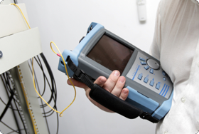
We looked at the pin-outs and some network diagrams. Now consider the devices that we need to measure on optics. It is an optical reflectometer and optical tester.
I must say that there are a lot of different and extremely expensive instruments for measurements on optics: all sorts of testers, spectrum analyzers, meters of various types of dispersion, complex network analyzers, specialized and laboratory reflectometers, and so on. But we will not consider all this, since our task is not laboratory research and not the operation of a first-class highway at the highest level, when it is not a pity for several millions of devices, but the average statistical measurements at the average communication facility during its construction and operation.
Optical reflectometers
Optical reflectometer is, as a rule, a computerized measuring device, whose work is based on sending pulses into the optical line and analyzing what is reflected back due to backscattering of the fiber and reflection from inhomogeneities. OTDRs are also available for copper cables, but we will only look at optical ones. I will discuss the installation of measurement settings and analysis of the resulting measurement of the reflectogram in the next section, and now I’m going to talk a little about the OTDRs themselves.
Reflectometers are expensive and complex electronic devices. Those who are engaged in optical communication, reflectometer is very necessary, without him as without hands. This is like a telephonist without a rotary tube or a SKS installer without a LAN tester: you can do something, but troubleshooting will cause a lot of trouble, besides, reflectograms must be attached to the documentation for the constructed communication object.
Using an OTDR, we can look at the total length of the track, total and kilometric attenuation, find damage, often find an error in splicing, assess whether the couplings are well welded along the entire length of the fiber, whether there is a bend or a bad cross-over junction.
Reflectometers are different, from the most simple to measure tracks at short distances (the price is around 50-80 tr.) To complex multifunctional modular measuring complexes for long lines (the price can well pass for a million). There are highly specialized reflectometers, for example, Brillouin, which will show us where there is increased tensile stress in the optical fiber. There are complexes for measuring various types of dispersion on long lines. There are stationary complexes of online monitoring of lines, the capabilities of which are superior to a conventional reflectometer, for example, Selektel mentioned such a complex.
But we will look at simple general purpose reflectometers.
On average, a normal reflectometer costs 250-500 + thousand rubles.
I want to say right away that I have a lot of experience with only one reflectometer model (inexpensive domestic Svyazpribor OTDR Gamma Lite), and only relatively few used the EXFO FTB-200 reflectometer (first revision), FTB-100, Yokogawa AQ7270, some then Fluke, Svyazpribor OTDR Gamma Lux and another, maybe a couple of models. Relatively little - this means that I used the device several times or dozens of times, I appreciated the device as a whole and got the measurements I needed, but I didn’t remember the statistics and I don’t remember where the interface is located. So in this regard, the “variety” of reflectometers for me was not too large and there was no coverage of the general situation (as with welding machines). However, knowing the principles of reflectometry and being able to work with a computer and generally with graphical interfaces (that is, be able to read and comprehend what a clever machine is writing to you), it is possible to master any OTDR at a sufficient level in half an hour or less. It's like with an oscilloscope: for a random person, any oscilloscope has a bunch of incomprehensible pens, buttons, connectors and icons, and one who has worked on one oscilloscope for a long time and knows the principles can quickly master another. So I can not give a classification and comparative analysis of different models - I can only tell you by the example of my current reflectometer. A review and comparison of different reflectometers (as well as a comparison of optical welding machines) is a topic for a separate large article that can be written, perhaps, only by those who sell a large range of reflectometers, or by an employee of a large company that has a fleet of dozens of different reflectometers. same as with welding machines). Who needs more detailed and up-to-date information on the models and their capabilities - I advise you to look here and also download the TCS catalog - it is very detailed and painted there with pictures.
About the analysis of the trace I will tell in the next article. But if someone wants to quickly - then here's another useful link . It is very detailed about reflectometry; I, of course, cannot convey all this within the framework of the article, so I’ll just say: learning to measure a trace well with an OTDR is quite difficult, there are many nuances.
If you do not take into account any antediluvian reflectometers or primitive non-reflectometers that indicate only the distance to the nearest damage, then with a modern reflectometer the measurement result is an reflectogram - this is a small file in the .sor, .trc format or in some other format. I will write about reflectograms and their analysis in the next part (I wanted to fit everything into one, but it turns out too voluminous). It can be opened both on the reflectometer itself and on the computer in the corresponding program. Unfortunately, I am not a programmer at all and I don’t know what structure these files have inside. For those who are interested in digging through, I’ll attach an archive with windows-program for analyzing traces from Yokogawa (opens only .sor) + several traces in the formats.sor and .trc. There are many programs for viewing and analyzing traces, I'm used to this. By the way: there is a program called SorTraceViewer, which can (with restrictions) create the required trace. :) Sometimes it is very necessary for reporting, when the authorities themselves do not know what to do, but there is no possibility to remove the real reflectogram and it is impossible to find a similar one in the bins, or the route has not yet been done, and reporting is already necessary.
In the .sor format, most OTDRs are saved, in the .trc format, EXFO’s OTDRs, and possibly some others. A reflectogram is, roughly speaking, a plot of attenuation (y-axis) versus path length (x-axis). It should be understood that the reflectogram is not a mathematical abstraction, but a reflection of what is happening in the line, and you can see quite a lot of interesting things on it.
What can a universal modern reflectometer?
a) Remove traces in automatic and manual modes.
b) On the built-in display, view them, carry out the analysis, immediately recognize the attenuation at a specific section of interest, at the connection (coupling or cross), as well as the length of the route (all or part we need).
c) It has built-in flash memory, as well as a USB port for a flash drive and a file manager to transfer traces. Old reflectometers could have a floppy disk, a COM port, and other interfaces for the same purpose.
d) Often there are built-in functions of the optical tester, it is very convenient and really necessary.
e) Often there is an optical outlet with a source of red light (as in a laser pointer) for visual continuity (more precisely, illumination) of fibers at short distances (up to about 5 km). Usually called VFL. It helps in finding "crosses", bends of fibers in cassettes and broken fibers, and simply helps to quickly find the right fiber in the bundle.
e) There may be a built-in tester for digital streams and other features.
g) Able to work without a network due to built-in batteries.
g) The attached software for the computer is able to compile a ready-made measurement report, with a reflectogram image and trace parameters.
h) Sometimes it has the ability to connect additional modules and accessories, for example, a microscope with a camera and an illumination to monitor the condition of the ends of the connectors at patch cords and pigtails.
i) If the platform is modular, you can install different modules into the “basket” that we need: for example, a reflectometer module and some module of testing digital streams.
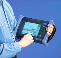
The size of modern reflectometers is different: from the size of a large smartphone to a small suitcase.
In nature, there are also reflectometers-modules that are connected to a computer, but I have not come across such live ones.
Control methods are also different: some models have a touch screen, some sets of buttons, and some even have a keyboard.
As for the architecture, it is usually ARM with Windows CE, although I saw a reflectometer with Windows XP on board. Perhaps there are on other operating systems. And the new EXFO FTB-200 revision, if I'm not mistaken, works on the Intel Atom. I heard rumors that the guys went to the Internet with a reflectometer and even played DOS games on it. =) On the one hand, it is interesting to get out of the original shell into the bare OS and climb there, on the other hand, the device is expensive and it’s better not to do what you don’t want on it. This is how to allow users to put toys, surf the Internet and drive a screw on a responsible server. I remember a case when a person traveling across the reflectometer disk through a still very imperfect touchscreen, accidentally renamed one folder containing the autoloaded components of the branded shell with all measurement programs, and did not notice this, and after rebooting the reflectometer turned simply into a big smartbook for half a million with Windows CE. Winda could not find the files of the "measuring" shell, which normally loaded automatically. Fortunately, there was a number of the same reflectometer, we guessed what could be the case, by comparing the contents of the discs, the renamed folder was found and renamed back, and it all worked.
According to the design of the case, many models are made with rubber corners and with splash protection, for use in the field. This, of course, is a plus, but you still shouldn't drop the reflectometer. Some models have a built-in cooler for cooling, it is believed that this is a minus (it pumps dust in the fields), but with careful handling, this is all nonsense.
And, finally, the most important classification is by the measuring module, by its sensitivity, or by the value of the dynamic range. That is what determines the price of the device to a great extent.
Cheap reflectometers have a narrow dynamic range (an approximate analog is an ISO on a camera), which means that they cannot measure a long line (it’s normal not to take a picture of a contrast or dark scene), or you have to distort for a long time with settings and wait a very long time (and still the end of the line on such a reflectometer sinks in noise). Accordingly, if we get a track with very poor welding or a very dirty cross-connection, on a cheap reflectometer we will see nothing behind this poor connection, and on a sensitive reflectometer there is a chance that we have enough range, albeit with noises, but see what happens next after this bad connection. Plus, with cheap OTDR, the OTDR itself is noisy and uneven when zoomed in: a small attenuation on a well-welded coupling or a small crack may simply not be noticeable, and when you need to find all the couplings on the track and find out the distances to them and between them, this becomes a problem. In addition, in my not very rich experience, cheap OTDRs suffer from the quality problems of both software and manufacturing. The software can cause not only strange irritating glitches, but also directly interfere with measuring, drawing the wrong trace and misleading.
Expensive reflectometers, respectively, allow you to quickly and accurately measure long highways, do not give out unpleasant surprises, allow you to get well-repeated, informative reflectograms that are well-repeated from measurement to measurement.
I'll tell you a little about the devices that I worked with.
My main working reflectometer now is the domestic Svyazpribor OTDR Gamma Lite .

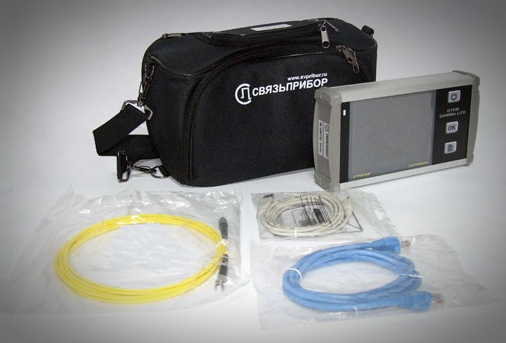
I have at my disposal 2 identical such devices with slightly different firmware. This device has both significant advantages and very significant disadvantages. In short, you can use it, but glitches are annoying and can be misleading. For a compact form factor and iron 5 with a minus, for buggy software and reliability - threefold with a minus.
.
I will hide the pros and cons under the spoiler, There is a lot of text, but not everyone is interested
Pros:
a) Compactness.
b) A touch screen that supports fingers and any stylus.
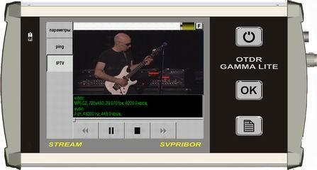
c) Built-in red laser for illumination (this is an option), tester functions and other features. For example, there is a terminal for testing IPTV (it did not happen).
d) Low price for reflectometers (about 90,000 rubles, cost 80,000 in 2010).
d) A fairly capacious battery.
e) USB port for flash drives (to drop traces on it) and mini-USB (to connect the device to the computer as a removable storage device with a capacity of 1 GB - this is more than enough for trace files).
g) The body is partially aluminum.
g) While working at noon under the hot southern sun, it used to be heated up very much - and this did not affect his work.
Minuses:
a) A narrow dynamic range of 34/32 dB (1310/1550 nm), which is why they cannot measure the long line. So, in my experience, this device hardly breaks 40-50 km, it is no longer enough (the end of the route is sinking in noise and the measurement time is stretched to indecently long). True, in the memory of the new device, when I received it, there was a very beautiful and not at all noisy reflectogram of a track about 75 km long, but no matter how hard I tried, I could not get this result on long tracks. Maybe, of course, it’s my hands are crooked, or I didn’t have the patience to wait an hour for the results of one measurement, or the photocell has already degraded, but somehow it becomes problematic to take a trace trace over 25 km long with this device. At best, each measurement will have to wait for many minutes, which means that the cross-port to 64 ports will have to be measured in more than one day. The impression is that when setting measurement parameters for a route over 25 km, the growth of the brakes begins on the exponent: at the “25 km” limit, it is still possible to work, at 50 it is almost not. Less than 25 all flies.
b) Poor build quality and materials: on one device the Mini-USB port soon fell off for no particular reason and the USB fell off, on the second after 2 years the VHL luminaire module stopped working with red light, in both devices after about 2.5 years it was not very intense exploitation there were breaks in the power cords (both in power and low-voltage), I had to take a screwdriver and a soldering iron and solder the wires, and also change the plug. When shaking inside both devices, something heavy is hanging out, it seems that this has not fixed the battery properly.
c) Annoyingly poor software quality. The main disadvantage of this device, forgive me is the programmers from Svyazpribor! There are often strange glitches and unexpected windows with errors, indecently long measurements at long track lengths and wild lags when trying to cancel such a measurement started.
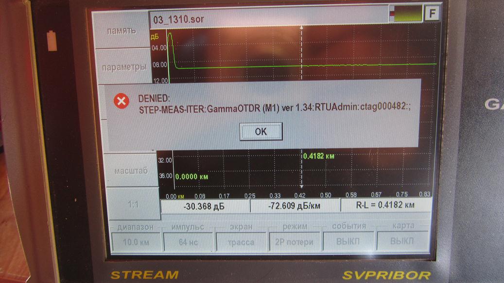
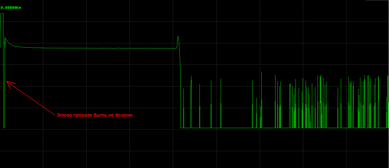
Frequent spontaneous shutdowns, reboots and reset settings. It happens that the device does not find the OTDR module (that is, the module of the OTDR itself) during cold start-up or simply does not complete the download at a certain stage, but if after this error you send the device to sleep mode and wake it up, everything is located. And sometimes it is not: somehow my partner went to another city on a business trip and there the device refused to load, I had to use the device of the local brigade. Upon returning, the device soon started working again. Sometimes the glitch also manifests itself in the measurement results, and sometimes it is so tricky and confusing that it is not easy to formulate a bug report ... You can easily get astray and incorrectly determine the distance to the cliff, respectively, people will go looking for a cliff not there: the reflectogram is drawn, but how faster than usual, some crooked, and guess what a glitch, especially if you have no experience with such a tricky device)) The following is likely to happen: after several normally drawn reflectograms, the h is silently reset With settings, including the length range set (and the default range is 300 or 500 m on different firmwares), the OTDR starts to draw what it sees on these 300 meters, but for some reason it draws a drop in noise, similar to the end of the track ... Or so: on a smaller scale, everything is fine, and when the scale is less than a step at a time - the working area of the trace is generally drawn somewhere outside the permissible area vertically, and it is simply not in the trace file, only the beginning of the trace is visible, signs of the final peak and noise . With automatic analysis, it can show one trace length, and with manual setting of cursors exactly at the beginning and end of the trace, the length of the trace will be slightly different. With some special combination of settings and trace parameters, strange dips or offsets appear at the beginning of the trace, due to which the customer may not accept documentation (I suppose this occurs at certain lengths of the measured trace — maybe some wave and resonance effects are incorrectly processed in the fiber, or because of the dirty port in the cross, but other OTDRs do not have this).
In the case when a priori only noise should be shown (for example, if you start the measurement without unscrewing the cap on the port and not connecting it to the road), it can draw something similar to the road, with a working area, an indistinct end and a noise area. In case of a bad connection on the connector (dirt on the end of the patch cord) and, accordingly, the presence of a smooth transition of the initial zone of the illumination to the path zone, the analyzer can analyze the “events” in this place (i.e., decide that there are several places where the signal fades). (300 ) ( , , ). And so on. , . , , — . ( OTDR) . , , 2 . , . , , , . . , , , 1310, 1550 , 2 . Yokogawa .
) : , 1 (FC-FC) 1 (8P8C-8P8C) -, USB-mini USB, «» , (+ ). , : «» . -, FC-, — : FC, SC, LC, ST, FC/APC, LC/APC, SC/APC. , : , , , , , . , , -.
) .
) , , 45°: , .
) : ( ), Windows CE- , ( ).
) . , .. , . Drag'n'Drop: , . , , , , , , , «» . , , «». : QWERTY, ( -, ), , , .
) , , : «» .
a) Compactness.
b) A touch screen that supports fingers and any stylus.
c) Built-in red laser for illumination (this is an option), tester functions and other features. For example, there is a terminal for testing IPTV (it did not happen).
d) Low price for reflectometers (about 90,000 rubles, cost 80,000 in 2010).
d) A fairly capacious battery.
e) USB port for flash drives (to drop traces on it) and mini-USB (to connect the device to the computer as a removable storage device with a capacity of 1 GB - this is more than enough for trace files).
g) The body is partially aluminum.
g) While working at noon under the hot southern sun, it used to be heated up very much - and this did not affect his work.
Minuses:
a) A narrow dynamic range of 34/32 dB (1310/1550 nm), which is why they cannot measure the long line. So, in my experience, this device hardly breaks 40-50 km, it is no longer enough (the end of the route is sinking in noise and the measurement time is stretched to indecently long). True, in the memory of the new device, when I received it, there was a very beautiful and not at all noisy reflectogram of a track about 75 km long, but no matter how hard I tried, I could not get this result on long tracks. Maybe, of course, it’s my hands are crooked, or I didn’t have the patience to wait an hour for the results of one measurement, or the photocell has already degraded, but somehow it becomes problematic to take a trace trace over 25 km long with this device. At best, each measurement will have to wait for many minutes, which means that the cross-port to 64 ports will have to be measured in more than one day. The impression is that when setting measurement parameters for a route over 25 km, the growth of the brakes begins on the exponent: at the “25 km” limit, it is still possible to work, at 50 it is almost not. Less than 25 all flies.
b) Poor build quality and materials: on one device the Mini-USB port soon fell off for no particular reason and the USB fell off, on the second after 2 years the VHL luminaire module stopped working with red light, in both devices after about 2.5 years it was not very intense exploitation there were breaks in the power cords (both in power and low-voltage), I had to take a screwdriver and a soldering iron and solder the wires, and also change the plug. When shaking inside both devices, something heavy is hanging out, it seems that this has not fixed the battery properly.
c) Annoyingly poor software quality. The main disadvantage of this device, forgive me is the programmers from Svyazpribor! There are often strange glitches and unexpected windows with errors, indecently long measurements at long track lengths and wild lags when trying to cancel such a measurement started.
Frequent spontaneous shutdowns, reboots and reset settings. It happens that the device does not find the OTDR module (that is, the module of the OTDR itself) during cold start-up or simply does not complete the download at a certain stage, but if after this error you send the device to sleep mode and wake it up, everything is located. And sometimes it is not: somehow my partner went to another city on a business trip and there the device refused to load, I had to use the device of the local brigade. Upon returning, the device soon started working again. Sometimes the glitch also manifests itself in the measurement results, and sometimes it is so tricky and confusing that it is not easy to formulate a bug report ... You can easily get astray and incorrectly determine the distance to the cliff, respectively, people will go looking for a cliff not there: the reflectogram is drawn, but how faster than usual, some crooked, and guess what a glitch, especially if you have no experience with such a tricky device)) The following is likely to happen: after several normally drawn reflectograms, the h is silently reset With settings, including the length range set (and the default range is 300 or 500 m on different firmwares), the OTDR starts to draw what it sees on these 300 meters, but for some reason it draws a drop in noise, similar to the end of the track ... Or so: on a smaller scale, everything is fine, and when the scale is less than a step at a time - the working area of the trace is generally drawn somewhere outside the permissible area vertically, and it is simply not in the trace file, only the beginning of the trace is visible, signs of the final peak and noise . With automatic analysis, it can show one trace length, and with manual setting of cursors exactly at the beginning and end of the trace, the length of the trace will be slightly different. With some special combination of settings and trace parameters, strange dips or offsets appear at the beginning of the trace, due to which the customer may not accept documentation (I suppose this occurs at certain lengths of the measured trace — maybe some wave and resonance effects are incorrectly processed in the fiber, or because of the dirty port in the cross, but other OTDRs do not have this).
In the case when a priori only noise should be shown (for example, if you start the measurement without unscrewing the cap on the port and not connecting it to the road), it can draw something similar to the road, with a working area, an indistinct end and a noise area. In case of a bad connection on the connector (dirt on the end of the patch cord) and, accordingly, the presence of a smooth transition of the initial zone of the illumination to the path zone, the analyzer can analyze the “events” in this place (i.e., decide that there are several places where the signal fades). (300 ) ( , , ). And so on. , . , , — . ( OTDR) . , , 2 . , . , , , . . , , , 1310, 1550 , 2 . Yokogawa .
) : , 1 (FC-FC) 1 (8P8C-8P8C) -, USB-mini USB, «» , (+ ). , : «» . -, FC-, — : FC, SC, LC, ST, FC/APC, LC/APC, SC/APC. , : , , , , , . , , -.
) .
) , , 45°: , .
) : ( ), Windows CE- , ( ).
) . , .. , . Drag'n'Drop: , . , , , , , , , «» . , , «». : QWERTY, ( -, ), , , .
) , , : «» .
The OTDR Gamma Lux reflectometer feels the same, only it is made in the form of a case and is controlled by buttons, the screen is normal, without a sensor.
In spite of all the shortcomings, it is possible to work with this and similar inexpensive devices, measuring small tracks, preferably up to 25 km and no more than 50 (FTTB, for example), conducting input cable control, etc. For your price, this is still an excellent device, compact and functional, if you learn not to get annoyed at quite frequent glitches, accept the above disadvantages and do not demand too much from him.
I also worked on several other devices, I will describe in brief the impressions.
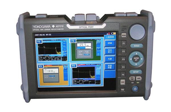
Yokogawa AQ7270 (and Yokogawa like him). This is a good device from Japan, many use it, but it is also not without flaws.
Pros:
a) High quality of the received reflectograms.
b) Although the screen is not touch and there are a lot of buttons, you get used to it quickly.
c) The body is sheathed with rubber.
d) Good reliability, good workmanship.
e) You can set up a macro for automation: one click will completely measure, save and be referred to as one fiber at two wavelengths.
e) There is a red light VHL.
g) There are many models with different dynamic range of modules, respectively, and the price varies.
Minuses:
a) High price.
b) Large size and weight.
c) It’s not all perfect software either: it can sometimes take a trace with strange glitches or put events where there are none.
d) Not enough touch screen.
EXFO FTB-200 , first revision.
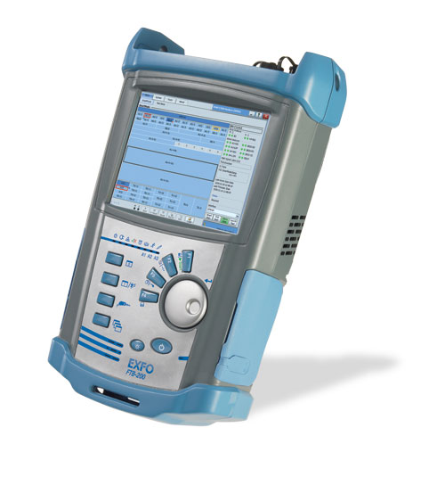
What there was a measuring module, to be honest, I do not remember. Excellent, but very expensive professional device from Canada. This is a modular platform for 2 modules. Touch screen, excellent reflectogram quality, optical microscope connection, a lot of features, excellent dynamic range. Comes with a durable bag. Among the shortcomings - large dimensions and weight (the size of a small backpack, and a bag the size of a normal backpack), the presence of a fan. The first revision is already outdated. The second revision did not have to be used, but apparently, it is also “at the level”.
EXFO FTB-100 .
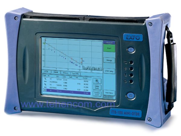
Also a good reflectometer, but already very outdated: it is still from the 90s. There is already a large touch screen - and there is still a floppy drive and a COM port. There is no USB. It feels like FTB-200, but much slower.
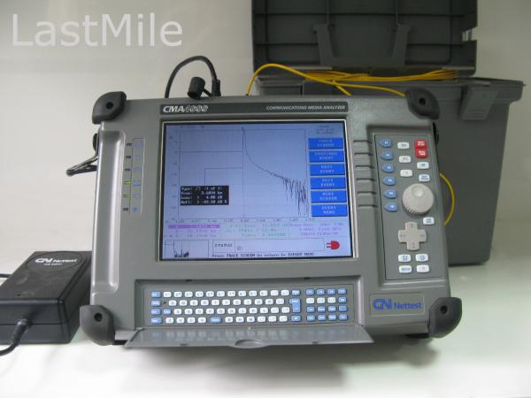
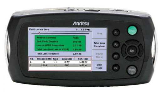
There are lines of models of reflectometers from other companies, I heard about many of them, but I did not have to use it: Fluke, FOD, Anritsu, Fujikura, NetTest and others. I know that Anritsu is also a popular brand in Russia.
Now briefly tell you about the optical testers.
Optical testers
The optical tester is an electronic digital instrument for measuring on optics. It is generally cheaper and simpler than an OTDR, although a high-quality tester from a recognized firm can be much more expensive than a simple OTDR.
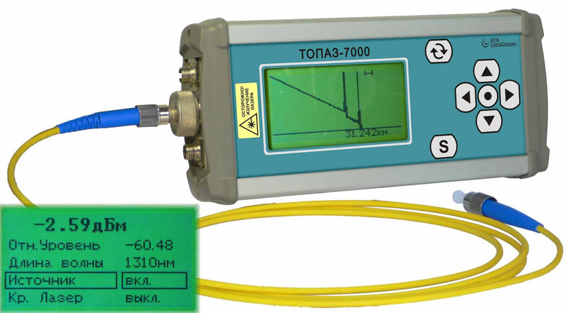
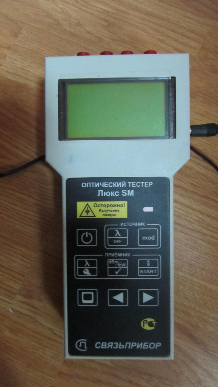
The tester is needed first of all to show the received signal power (in dB, in dBm or in W), and also to work as a transmitter for another tester at the far end of the track. Although there are relatively cheap sources of optical radiation at 1310/1550 nm, if you need only a blunt source, and not a full tester (an example of a source is the Svyazpribor Lux S).
In addition to the main purpose, some testers can have additional features: a color screen, the ability to connect a microscope camera to monitor connector ends of patch cords and pigtails, the presence of a built-in primitive reflectometer, the presence of different types of modulation of the emitted signal. Some testers can only wavelengths of 1310 and 1550 nm, others allow you to set the wavelength smoothly, to an accuracy of units of nm, by measuring the line attenuation at wavelengths outside the windows of glass transparency.
How necessary is the tester to purchase? Not as much as a reflectometer, but still it is irreplaceable. According to the documents, the track (or cable at the input control) must be measured with both a reflectometer and testers, but the customer can only be satisfied with reflectograms, and usually they are really quite enough.
There should be two testers: one sends a signal to the line, the other at the far end looks at which level it comes. But since OTDRs often have the functions of a tester, you can, on the one hand, put the OTDR as a transmitter, and take it as a tester. Or vice versa.So usually they do.
A tester can look for tangled fibers, crosses and generally “call up” which port at cross-country A to which port of cross-country B comes. If the distance is short, this can be done visually with a red VHL laser (by the way, I also recommend to buy such a “pointer” with an optical outlet on the end, if your tester / reflectometer does not have a built-in “light”). But kilometers 5-6 and more, the red light no longer passes, fades (because its wavelength does not fall into the “transparency windows” of the fiber) - and then the tester becomes irreplaceable.
I worked with only two models of testers.
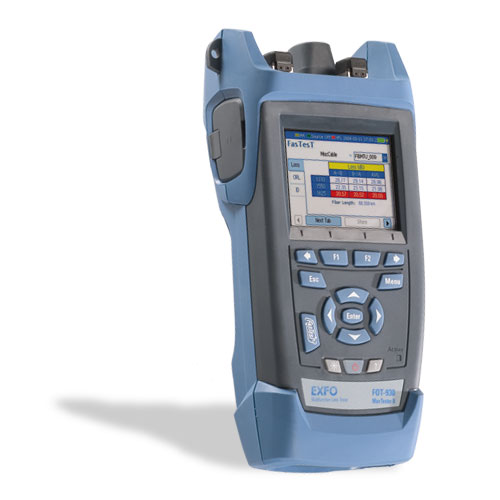
1) Expensive and heaped up Canadian EXFO FOT-930 (the price is about 250 TR - a lot for the tester).
2) Domestic Svyazpribor Lux SM (price about 50 tr.).
The first (EXFO) can do quite a lot of things, for example, you can connect a microscope module to it and watch on the small screen how dirty and scratched the end of a patch cord is. There is an auto-measurement function "FasTest". Disadvantages - rubber covers-plugs of connectors quickly fall off, the port of the microscope is weak and also quickly breaks out (there is some kind of S-Video). But for such a price, in my opinion, it is needed only for those who serve first-class optical highways and constantly measure them. When I served just such a highway, I used it. And in most cases a simple tester will do.
Svyazpriborovsky tester, in contrast to the above-described reflectometer with a bunch of bugs, I liked: simple and reliable, and the charge lasts a long time, and has a lot of functions. There is a bright red VHL-illumination and even a built-in trimmed reflectometer! You cannot save the reflectogram and take a closer look too (besides the resolution of the screen does not allow to see the details), but if for some reason there is no normal reflectometer at hand, you can simply see the distance to the damage.
Included is the same as a reflectometer, a bag (for a tester, it is not cramped), an FC-FC patch cord, a splitter, a passport, a power supply unit (also known as charging batteries). What is missing is a set of patch cords for different adapter standards.
How to measure the line testers?
One tester will be the transmitter, the other receiver. We connect them with clean patch cords through a clean socket (i.e., via the chain “transmitter port - patch cord 1 - socket - patch cord 2 - receiver port”), enable, tune to the same modulation, the same units of measurement and the same wavelength, and see what the receiving tester will show. This is our “reference zero”, it is even possible to reset the receiver’s readings in such a way that this reading is considered to be the reference zero. Then, when the transmitter is turned off, the receiver will show a strong “minus”. Next, we turn off the testers, disconnect the two patch cords on the outlet, do not forget to close the patch cord connectors with clean caps, and without unscrewing the other side of the patch cords from the instruments (so as not to introduce an extra error - when unscrewing / twisting the patch cord, attenuation can a little walk from time to time!) we carry the transmitter to one end of the route, the receiver to the other, connect it to the line (having cleaned the sockets and pigtails in the crosses) and take the measurement. The receiver will show some negative value (in decibels). When the receivers were near and 100% of the power fell from the transmitter to the receiver - we set that this is a reference zero. Now, part of the power is lost in our line, and a negative value on the receiver is the attenuation of our entire route. Divide by the optical length of our route - we get the kilometric attenuation (in dB / km). We measure at both wavelengths, 1310 and 1550 nm, and write the results in a notebook. Then we repeat for the following fibers. For special accuracy lovers, you can swap the instruments (or switch the transmitter tester to the receiver, and the receiver to the gear), measure it again and take the average value.This method of measuring line attenuation by testers is the most accurate, but very inconvenient and time consuming. Usually, the responsible trunk lines are measured once a year both by testers and the OTDR in both directions, and for simple lines with the tester they usually don’t bother and only look at the OTDR from one side, or even measure something only when the connection is lost. In the case of measurement with a reflectometer, there are some nuances, but in general, the measurement quality is quite good.In the case of measurement with a reflectometer, there are some nuances, but in general, the measurement quality is quite good.In the case of measurement with a reflectometer, there are some nuances, but in general, the measurement quality is quite good.
By myself I can say that I needed our tester very rarely. Mostly treated with a reflectometer. Therefore, I don’t have much experience with the tester and will not be able to tell you many interesting and tasty details, like about reflectometers in the future part.
That came to the end of my third article about working with optics. As always, I will be happy reviews and questions. In the next part we will look at what can be seen on the trace, how to analyze the route on it, and so on.
Source: https://habr.com/ru/post/208296/
All Articles