STM32 and USB-HID - it’s just
In the yard in 2014, and for the connection of microcontrollers with a PC, the most popular means is the usual serial port. It's easy to start working with him, he is simple in understanding to the primitiveness - just a stream of bytes.
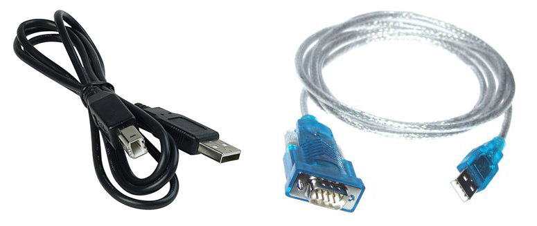
However, all modern standards have excluded the COM port from the PC and you have to use USB-UART adapters to get access to your project on the MC. He is not always at hand. Such an adapter does not always work stably due to driver problems. There are other disadvantages.
But every time there is a conversation about whether to use USB or serial port, there are many fans of the logical simplicity of the UART. And they have a reason. However, is it good to have an alternative?
I have long been asked to tell how to organize packet data exchange between a PC and a MK using the example of the STM32F103. I will give a ready-made working project and tell you how to adapt it to your needs. And so you decide - you need it or not.
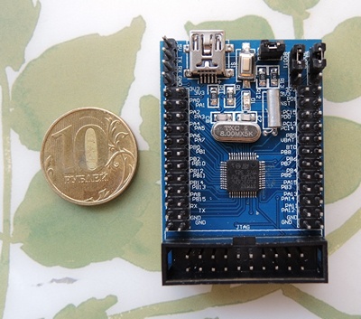
We have a board with a modern low-cost microcontroller STM32F103C8 with built-in hardware USB support, I told about it earlier
I said that the serial port has other disadvantages:
- Often the COM port is not in the PC or laptop
- the device needs to be fed separately
- even if there is a COM port in the PC, the signal levels must be matched: the PC uses the RS232 interface with differential levels of signals + 15V and -15V, and microcontrollers use TTL levels (+ 5V, + 3.3V, unipolar).
- Often in the system dozens of virtual COM ports are formed and finding the port that corresponds to your device may be difficult.
In turn, USB has been with us for many years and has its advantages:
-Ability to supply power from the HOST device
- Convenient implementation of batch exchange
-Ability to simultaneously connect to the device with several programs
-Ability to uniquely identify the connected device
- Hardware support in many modern MCs, which eliminates the need for adapters
USB functionality is extremely rich, but it raises a problem — it's not as simple to understand as with a serial interface. There is a separate class of devices - USB-HID, which do not require the installation of drivers, specifically designed to interact with humans and various input-output devices. Ideal for organizing data exchange with MK. I personally like the batch exchange mode. This is a convenient abstraction. In addition, parsing packet messages is somewhat easier and more convenient than working with a simple stream of bytes.
USB-HID is a fairly extensive class of devices, so first of all you have to choose which device we will create.
We can create an emulation of a keyboard, mouse, joystick, and other input devices, and we can create our device so as not to depend on a fairly rigid standard framework and freely exchange data with a PC.
I'll tell you how to make a Custom HID device. This gives maximum freedom. In order not to delay the article, I will try to tell as briefly as possible - there are many descriptions of the standard in the network and without me, but personally they helped me a little when it took to solve a specific task.
')
I use EmBlocks for development under STM32. You can use any convenient environment, the project is not very difficult to adapt.
Added to the basic structure of the project:
We add all these files to any project using USB.
For correct operation of the USB module, the frequency of the MK is important. Not all frequencies allow you to properly set the USB clocking. In our case, we use a crystal oscillator at 8 MHz and MK operates at 72 MHz, and a USB module at 48 MHz.
Just insert a few lines of code into main.c.
In the Set_System () function, the pin of the D + line uplift to the power is configured to programmatically connect / disconnect the device from the PC (not used in our board), the interrupt is set up, and the LEDs and buttons for the demonstration project are initialized.
In USB_Interrupts_Config (), interrupts are configured depending on the MK family (F10x, F37x, L1x are supported).
The USB_Init () function starts the USB module. If you need to temporarily disable USB operation for debugging, simply comment out this line.
Further, in an infinite loop, it is checked whether it was possible to configure the USB module when connected to a PC. If everything worked correctly and the device was successfully connected, the PC is on and is not in power saving mode, then the status will be CONFIGURED.
Next, it is checked whether the previous data transfer to the PC was completed and, if so, it prepares for sending a new packet in the RHIDCheckState () function .
USB-HID device can not initiate the transfer itself, because bus coordination is handled by the host device - the PC Therefore, when preparing the USB descriptor of our device, we write how often our device should be polled. According to the specification, the maximum polling frequency is 1 kHz and the maximum size of a packet transmitted at a time is 64 bytes. If this is not enough, you will have to use other modes of operation - like USB bulk, but you can’t do without drivers there.
For setting the interaction with the PC are responsible 3 descriptor:
In the comments everything is pretty transparent. Pay attention to DEVICE_VER_L, DEVICE_VER_H - these are constants from usb_desc.h, which you can change to identify the version of your device.
Here you should pay attention to the wMaxPacketSize constant - it defines the maximum packet size that we will exchange with the PC. The project is set up so that when it changes, the size of the buffers also changes. But do not forget that more than 0x40 according to the standard should not be specified. With this constant, be careful - if the transmitted packet is different in size - there will be problems!
The next constant with the comment bInterval is the device polling period in milliseconds. 32ms is set for our device.
This is the most important descriptor - it describes the protocol of the exchange and the functionality of the device. Its formation is not the easiest task. If you make a mistake in the formation of the descriptor - the device will stop working. The descriptor format is very hard. There is even a special utility HID Descriptor tool . And in the root of the project there is a file “RHID.hid” with the descriptor described above for editing in this utility. But if you do not understand what you are doing, it is better not to go.
For simplicity, I made two constants:
RPT3_COUNT - OUTPUT buffer size in bytes for transmitting the packet to the MC (in the example - 1 byte)
RPT4_COUNT - INPUT buffer size in bytes for transmitting the packet to the PC (4 bytes in the example)
The size of any of these buffers should not exceed wMaxPacketSize . Less is possible.
By the way, you can transform a Custom HID into another HID device, for example, a keyboard or a joystick, just by rewriting ReportDescriptor and changing the class and subclass of the device in the configuration descriptor.
Host (PC) and device (MK) exchange data packets of a predetermined structure - report. There can be quite a lot of packages, they can be foreseen for all occasions - for example, a package with data about some events in the device, a package with data that the PC requested, a package with a command for the MC. Anything. But the structure of all packages must be described in the RHID_ReportDescriptor structure.
PC and MK distinguish between ID reports, which is the first byte in the packet.
In our example, there are 4 types of reports:
If you have not fully understood how to form a report descriptor, then simply change the RPT3_COUNT and RPT4_COUNT constants, setting the required size of outgoing and incoming (from PC point of view) packets. The rest of the reports can simply not touch, they do not interfere. Do not forget that the first byte must be a report ID.
So, we configured our device by setting the PID, VID, version number, configured the size of incoming and outgoing packets and are ready to go.
Every 32ms, as we requested in the configuration descriptor, the host will poll us and, in the RHIDCheckState function, we check if we have something to send, then we create a data packet for the host.
The uint8_t Buffer [RPT4_COUNT + 1] array is defined as the size of the payload of the incoming (always viewed from the host's point of view) packet + byte ID. This is important - if the buffer size is different - there will be problems. Therefore, to change the buffer size, edit the value of the constant in usb_desc.h.
In the function, we collect data in a packet, set the PrevXferComplete = 0 flag, which says that the data is sent, and call the USB_SIL_Write and SetEPTxValid library functions to send data to the host.
That's it, the transfer of data to the host is complete.
Data reception is a bit more complicated - there are two ways to send data to a device — one of them is to use the Features described in the report descriptor, with the appropriate parameters via the SET_FEAUTRE function. This is some kind of abstraction, for beautifully managing a device with a bunch of functions so that you can call meaningful functions, and not just send a stream of bytes.
The second way is to work with the device as with a file — simply write the package into it as to a file. This method is called SET_REPORT . In fact, it works a little slower.
Our device supports both methods, which we told the host in the report descriptor.
Data sent by the SET_FEAUTRE method is processed by usb_prop.c
Here we check the first byte in the report and process the rest of the packet according to it — we control the LEDs or simply take the byte sent to us by the host and put it in the packet for later sending back to the RHIDCheckState function.
Under Report_Buf, wMaxPacketSize bytes is reserved to fit into any packet that the host sends us.
Data sent by the SET_REPORT method is processed in usb_endp.c
Here, almost the same thing, you only need to pick up the data yourself by calling USB_SIL_Read (EP1_OUT, Receive_Buffer) and finally report that we ended up by calling SetEPRxStatus (ENDP1, EP_RX_VALID);
We learned how to configure the device, transmit and receive data in packets of the required size with the frequency we need.
We assemble the project and flash it into the device.
It will work like this:
The project supports interaction with the USB HID Demonstrator utility from ST Microelectronics.
The Device capabilities page displays the capabilities described in the Report Descriptor.
Input / Output transfer allows you to manually send data to the device and see the package that comes from it.
Graphic view allows you to control LEDs, Led 1, Led 2 checkboxes by setting the corresponding Report ID, as well as transfer a byte with the slider (ReportID = 3)
I also wrote a small demo software that automatically determines the connection to the computer and the disconnection of our device by its VID and PID, displays the status - connected / disconnected by the indicator next to the Auto Connect checkbox
Radio Send Send allows you to select the method for sending data to the device.
Report: displays the packet received from the device byte-by-byte, starting with the ReportID.
Clicking on the LEDs below - control the LEDs of the device. Their status displays the current state of the device. Read from the report from the device.
Moving the slider, we send the Report with ID = 3 and the value corresponding to the position of the slider. The device will return this value in 4 byte report.
In the dropdown combo box, the HID devices found in the system are displayed, and if our device is found, its name is displayed.
Download everything you need on GitHub . Composed of:
DT - HID Descriptor tool
tstHID-STM32F103 - project for EmBlocks
USB HID Demonstrator - utility from ST Microelectronics
HIDSTM32.exe - my Delphi demo soft on a similar feature, but not requiring configuration
If you have any questions - write in the comments. I will try to answer. I tried not to drown the essence in a heap of trifles in order to develop a common understanding. The rest can already be understood by studying the project. But if you need to quickly make your device, and there is no time to climb into the jungle - I described everything that you need.
PS By default, when the host goes into power saving mode, the device goes to sleep with it, and if you connect the device to a sleeping PC, it will also go into a slip. Therefore, if we just plug the power supply into the device or are powered from the battery, then it will not work, considering that it is connected to the sleeping PC (configuration packages will not come from the power supply exactly). I changed the library so that the device worked and when I connected, just the BP. Therefore, the device will work both when connected to a PC and autonomously. (It took me a long time to figure it out.)
However, all modern standards have excluded the COM port from the PC and you have to use USB-UART adapters to get access to your project on the MC. He is not always at hand. Such an adapter does not always work stably due to driver problems. There are other disadvantages.
But every time there is a conversation about whether to use USB or serial port, there are many fans of the logical simplicity of the UART. And they have a reason. However, is it good to have an alternative?
I have long been asked to tell how to organize packet data exchange between a PC and a MK using the example of the STM32F103. I will give a ready-made working project and tell you how to adapt it to your needs. And so you decide - you need it or not.
We have a board with a modern low-cost microcontroller STM32F103C8 with built-in hardware USB support, I told about it earlier
I said that the serial port has other disadvantages:
- Often the COM port is not in the PC or laptop
- the device needs to be fed separately
- even if there is a COM port in the PC, the signal levels must be matched: the PC uses the RS232 interface with differential levels of signals + 15V and -15V, and microcontrollers use TTL levels (+ 5V, + 3.3V, unipolar).
- Often in the system dozens of virtual COM ports are formed and finding the port that corresponds to your device may be difficult.
In turn, USB has been with us for many years and has its advantages:
-Ability to supply power from the HOST device
- Convenient implementation of batch exchange
-Ability to simultaneously connect to the device with several programs
-Ability to uniquely identify the connected device
- Hardware support in many modern MCs, which eliminates the need for adapters
USB functionality is extremely rich, but it raises a problem — it's not as simple to understand as with a serial interface. There is a separate class of devices - USB-HID, which do not require the installation of drivers, specifically designed to interact with humans and various input-output devices. Ideal for organizing data exchange with MK. I personally like the batch exchange mode. This is a convenient abstraction. In addition, parsing packet messages is somewhat easier and more convenient than working with a simple stream of bytes.
HID profile selection
USB-HID is a fairly extensive class of devices, so first of all you have to choose which device we will create.
We can create an emulation of a keyboard, mouse, joystick, and other input devices, and we can create our device so as not to depend on a fairly rigid standard framework and freely exchange data with a PC.
I'll tell you how to make a Custom HID device. This gives maximum freedom. In order not to delay the article, I will try to tell as briefly as possible - there are many descriptions of the standard in the network and without me, but personally they helped me a little when it took to solve a specific task.
')
Project structure
I use EmBlocks for development under STM32. You can use any convenient environment, the project is not very difficult to adapt.
Added to the basic structure of the project:
- Folder USB-FS with the library "STM32F10x, STM32L1xx and STM32F3xx USB-FS-Device Driver" version 4.0.0.
- In the folders Inc and Src files:
platform_config.h - here are the definitions related to the specific board and the MK family
stm32_it.h, stm32_it.c - interrupt handlers are defined here
usb_conf.h, usb_endp.c - this defines end points (Endpoint), sizes and addresses of their buffers, handler functions
usb_desc.h, usb_desc.c - information about the device itself is collected here - how it will be determined when connected to a PC and the size and format of data packets are determined
hw_config.c - here all work is collected with sending data to PC
hw_config.h, usb_istr.h, usb_prop.h, usb_pwr.h
usb_istr.c, usb_prop.c, usb_pwr.c - are needed for the USB-FS library to work, but it's not necessary to climb into them
We add all these files to any project using USB.
USB initialization
For correct operation of the USB module, the frequency of the MK is important. Not all frequencies allow you to properly set the USB clocking. In our case, we use a crystal oscillator at 8 MHz and MK operates at 72 MHz, and a USB module at 48 MHz.
Just insert a few lines of code into main.c.
main.c
/* Includes ------------------------------------------------------------------*/ #include "hw_config.h" #include "usb_lib.h" #include "usb_pwr.h" /* Private variables ---------------------------------------------------------*/ __IO uint8_t PrevXferComplete = 1; int main(void) { Set_System(); USB_Interrupts_Config(); Set_USBClock(); USB_Init(); while (1) { if (bDeviceState == CONFIGURED) { if (PrevXferComplete) { RHIDCheckState(); } } } } In the Set_System () function, the pin of the D + line uplift to the power is configured to programmatically connect / disconnect the device from the PC (not used in our board), the interrupt is set up, and the LEDs and buttons for the demonstration project are initialized.
In USB_Interrupts_Config (), interrupts are configured depending on the MK family (F10x, F37x, L1x are supported).
The USB_Init () function starts the USB module. If you need to temporarily disable USB operation for debugging, simply comment out this line.
Further, in an infinite loop, it is checked whether it was possible to configure the USB module when connected to a PC. If everything worked correctly and the device was successfully connected, the PC is on and is not in power saving mode, then the status will be CONFIGURED.
Next, it is checked whether the previous data transfer to the PC was completed and, if so, it prepares for sending a new packet in the RHIDCheckState () function .
Packet size and transmission frequency
USB-HID device can not initiate the transfer itself, because bus coordination is handled by the host device - the PC Therefore, when preparing the USB descriptor of our device, we write how often our device should be polled. According to the specification, the maximum polling frequency is 1 kHz and the maximum size of a packet transmitted at a time is 64 bytes. If this is not enough, you will have to use other modes of operation - like USB bulk, but you can’t do without drivers there.
For setting the interaction with the PC are responsible 3 descriptor:
Device handle
/* USB Standard Device Descriptor */ const uint8_t RHID_DeviceDescriptor[RHID_SIZ_DEVICE_DESC] = { RHID_SIZ_DEVICE_DESC, // USB_DEVICE_DESCRIPTOR_TYPE, // bDescriptorType - , . - Device descriptor 0x00, 0x02, // bcdUSB - USB . 2.0 // , , USB. , 0x00, //bDeviceClass 0x00, //bDeviceSubClass 0x00, //bDeviceProtocol 0x40, //bMaxPacketSize - Endpoint 0 ( ) // VID PID, , . 0x83, 0x04, //idVendor (0x0483) 0x11, 0x57, //idProduct (0x5711) DEVICE_VER_L, DEVICE_VER_H, // bcdDevice rel. DEVICE_VER_H.DEVICE_VER_L // , , . // // VID/PID . 1, //Index of string descriptor describing manufacturer 2, //Index of string descriptor describing product 3, //Index of string descriptor describing the device serial number 0x01 // bNumConfigurations - . . } ; /* CustomHID_DeviceDescriptor */ In the comments everything is pretty transparent. Pay attention to DEVICE_VER_L, DEVICE_VER_H - these are constants from usb_desc.h, which you can change to identify the version of your device.
Configuration descriptor (describes device capabilities)
/* USB Configuration Descriptor */ /* All Descriptors (Configuration, Interface, Endpoint, Class, Vendor */ const uint8_t RHID_ConfigDescriptor[RHID_SIZ_CONFIG_DESC] = { 0x09, // bLength: USB_CONFIGURATION_DESCRIPTOR_TYPE, // bDescriptorType: - RHID_SIZ_CONFIG_DESC, 0x00, // wTotalLength: 0x01, // bNumInterfaces: 0x01, // bConfigurationValue: 0x00, // iConfiguration: , 0xE0, // bmAttributes: , USB 0x32, // MaxPower 100 mA: 100 /************** ****************/ 0x09, // bLength: USB_INTERFACE_DESCRIPTOR_TYPE, // bDescriptorType: - 0x00, // bInterfaceNumber: - 0 0x00, // bAlternateSetting: , 0x02, // bNumEndpoints - . 0x03, // bInterfaceClass: - HID // , , // HID- 0x00, // bInterfaceSubClass : . 0x00, // nInterfaceProtocol : 0, // iInterface: , // , - HID /******************** HID ********************/ 0x09, // bLength: HID- HID_DESCRIPTOR_TYPE, // bDescriptorType: - HID 0x01, 0x01, // bcdHID: HID 1.1 0x00, // bCountryCode: ( ) 0x01, // bNumDescriptors: report HID_REPORT_DESCRIPTOR_TYPE, // bDescriptorType: - report RHID_SIZ_REPORT_DESC, 0x00, // wItemLength: report- /******************** (endpoints) ********************/ 0x07, // bLength: USB_ENDPOINT_DESCRIPTOR_TYPE, // - endpoints 0x81, // bEndpointAddress: 1(IN) 0x03, // bmAttributes: - Interrupt endpoint wMaxPacketSize, 0x00, // wMaxPacketSize: Bytes max 0x20, // bInterval: Polling Interval (32 ms) 0x07, /* bLength: Endpoint Descriptor size */ USB_ENDPOINT_DESCRIPTOR_TYPE, /* bDescriptorType: */ /* Endpoint descriptor type */ 0x01, /* bEndpointAddress: */ /* Endpoint Address (OUT) */ 0x03, /* bmAttributes: Interrupt endpoint */ wMaxPacketSize, /* wMaxPacketSize: Bytes max */ 0x00, 0x20, /* bInterval: Polling Interval (32 ms) */ } ; /* RHID_ConfigDescriptor */ Here you should pay attention to the wMaxPacketSize constant - it defines the maximum packet size that we will exchange with the PC. The project is set up so that when it changes, the size of the buffers also changes. But do not forget that more than 0x40 according to the standard should not be specified. With this constant, be careful - if the transmitted packet is different in size - there will be problems!
The next constant with the comment bInterval is the device polling period in milliseconds. 32ms is set for our device.
Report Descriptor (describes the protocol)
const uint8_t RHID_ReportDescriptor[RHID_SIZ_REPORT_DESC] = { 0x06, 0x00, 0xff, // USAGE_PAGE (Generic Desktop) 0x09, 0x01, // USAGE (Vendor Usage 1) 0xa1, 0x01, // COLLECTION (Application) 0x85, 0x01, // REPORT_ID (1) 0x09, 0x01, // USAGE (Vendor Usage 1) 0x15, 0x00, // LOGICAL_MINIMUM (0) 0x25, 0x01, // LOGICAL_MAXIMUM (1) 0x75, 0x08, // REPORT_SIZE (8) 0x95, 0x01, // REPORT_COUNT (1) 0xb1, 0x82, // FEATURE (Data,Var,Abs,Vol) 0x85, 0x01, // REPORT_ID (1) 0x09, 0x01, // USAGE (Vendor Usage 1) 0x91, 0x82, // OUTPUT (Data,Var,Abs,Vol) 0x85, 0x02, // REPORT_ID (2) 0x09, 0x02, // USAGE (Vendor Usage 2) 0x15, 0x00, // LOGICAL_MINIMUM (0) 0x25, 0x01, // LOGICAL_MAXIMUM (1) 0x75, 0x08, // REPORT_SIZE (8) 0x95, 0x01, // REPORT_COUNT (1) 0xb1, 0x82, // FEATURE (Data,Var,Abs,Vol) 0x85, 0x02, // REPORT_ID (2) 0x09, 0x02, // USAGE (Vendor Usage 2) 0x91, 0x82, // OUTPUT (Data,Var,Abs,Vol) 0x85, 0x03, // REPORT_ID (3) 0x09, 0x03, // USAGE (Vendor Usage 3) 0x15, 0x00, // LOGICAL_MINIMUM (0) 0x26, 0xff, 0x00, // LOGICAL_MAXIMUM (255) 0x75, 0x08, // REPORT_SIZE (8) 0x95, RPT3_COUNT, // REPORT_COUNT (N) 0xb1, 0x82, // FEATURE (Data,Var,Abs,Vol) 0x85, 0x03, // REPORT_ID (3) 0x09, 0x03, // USAGE (Vendor Usage 3) 0x91, 0x82, // OUTPUT (Data,Var,Abs,Vol) 0x85, 0x04, // REPORT_ID (4) 0x09, 0x04, // USAGE (Vendor Usage 4) 0x75, 0x08, // REPORT_SIZE (8) 0x95, RPT4_COUNT, // REPORT_COUNT (N) 0x81, 0x82, // INPUT (Data,Var,Abs,Vol) 0xc0 // END_COLLECTION } This is the most important descriptor - it describes the protocol of the exchange and the functionality of the device. Its formation is not the easiest task. If you make a mistake in the formation of the descriptor - the device will stop working. The descriptor format is very hard. There is even a special utility HID Descriptor tool . And in the root of the project there is a file “RHID.hid” with the descriptor described above for editing in this utility. But if you do not understand what you are doing, it is better not to go.
For simplicity, I made two constants:
RPT3_COUNT - OUTPUT buffer size in bytes for transmitting the packet to the MC (in the example - 1 byte)
RPT4_COUNT - INPUT buffer size in bytes for transmitting the packet to the PC (4 bytes in the example)
The size of any of these buffers should not exceed wMaxPacketSize . Less is possible.
By the way, you can transform a Custom HID into another HID device, for example, a keyboard or a joystick, just by rewriting ReportDescriptor and changing the class and subclass of the device in the configuration descriptor.
What is Report
Host (PC) and device (MK) exchange data packets of a predetermined structure - report. There can be quite a lot of packages, they can be foreseen for all occasions - for example, a package with data about some events in the device, a package with data that the PC requested, a package with a command for the MC. Anything. But the structure of all packages must be described in the RHID_ReportDescriptor structure.
PC and MK distinguish between ID reports, which is the first byte in the packet.
In our example, there are 4 types of reports:
- REPORT_ID = 1 and 2 - the MC command to turn on / off the LED1 / LED2. It contains a 1-bit field with the desired state of the LED and supports sending both by the SET_REPORT method and the SET_FEATURE method (more on this later).
- REPORT_ID = 3 - sends one byte to the MC. Just to show how to transfer MK data. We will transfer the position of the slider.
- REPORT_ID = 4 is a report for transferring PC data. Returns information about the current status of the LEDs, buttons (if any) and returns the transmitted in the report with ID = 3 bytes to show that the data has been received.
If you have not fully understood how to form a report descriptor, then simply change the RPT3_COUNT and RPT4_COUNT constants, setting the required size of outgoing and incoming (from PC point of view) packets. The rest of the reports can simply not touch, they do not interfere. Do not forget that the first byte must be a report ID.
Exchange cycle
So, we configured our device by setting the PID, VID, version number, configured the size of incoming and outgoing packets and are ready to go.
Every 32ms, as we requested in the configuration descriptor, the host will poll us and, in the RHIDCheckState function, we check if we have something to send, then we create a data packet for the host.
RHIDCheckState - data sending function
/******************************************************************************* * Function Name : RHIDCheckState. * Description : Decodes the RHID state. * Input : None. * Output : None. * Return value : The state value. *******************************************************************************/ uint16_t btn1_prev, btn2_prev; uint8_t Buffer[RPT4_COUNT+1]; uint8_t RHIDCheckState(void) { uint16_t btn1=0, btn2=0; btn1 = GPIO_ReadInputDataBit(BTN1_PORT, BTN1_PIN); btn2 = GPIO_ReadInputDataBit(BTN2_PORT, BTN2_PIN); Buffer[0] = 4; Buffer[1] = btn1; Buffer[2] = btn2; Buffer[3] = (GPIO_ReadInputDataBit(LED_PORT, LED1_PIN) | GPIO_ReadInputDataBit(LED_PORT, LED2_PIN)<<1); /* Reset the control token to inform upper layer that a transfer is ongoing */ PrevXferComplete = 0; /* Copy buffer date info in ENDP1 Tx Packet Memory Area*/ USB_SIL_Write(EP1_IN, Buffer, RPT4_COUNT+1); /* Enable endpoint for transmission */ SetEPTxValid(ENDP1); return (btn1 | btn2<<1); } The uint8_t Buffer [RPT4_COUNT + 1] array is defined as the size of the payload of the incoming (always viewed from the host's point of view) packet + byte ID. This is important - if the buffer size is different - there will be problems. Therefore, to change the buffer size, edit the value of the constant in usb_desc.h.
In the function, we collect data in a packet, set the PrevXferComplete = 0 flag, which says that the data is sent, and call the USB_SIL_Write and SetEPTxValid library functions to send data to the host.
That's it, the transfer of data to the host is complete.
Data reception is a bit more complicated - there are two ways to send data to a device — one of them is to use the Features described in the report descriptor, with the appropriate parameters via the SET_FEAUTRE function. This is some kind of abstraction, for beautifully managing a device with a bunch of functions so that you can call meaningful functions, and not just send a stream of bytes.
The second way is to work with the device as with a file — simply write the package into it as to a file. This method is called SET_REPORT . In fact, it works a little slower.
Our device supports both methods, which we told the host in the report descriptor.
SET_FEATURE processing
Data sent by the SET_FEAUTRE method is processed by usb_prop.c
HID_Status_In function
/******************************************************************************* * Function Name : HID_Status_In. * Description : HID status IN routine. * Input : None. * Output : None. * Return : None. *******************************************************************************/ void HID_Status_In(void) { BitAction Led_State; if (Report_Buf[1] == 0) { Led_State = Bit_RESET; } else { Led_State = Bit_SET; } switch (Report_Buf[0]) { case 1: /* Led 1 */ if (Led_State != Bit_RESET) { GPIO_SetBits(LED_PORT,LED1_PIN); } else { GPIO_ResetBits(LED_PORT,LED1_PIN); } break; case 2: /* Led 2 */ if (Led_State != Bit_RESET) { GPIO_SetBits(LED_PORT,LED2_PIN); } else { GPIO_ResetBits(LED_PORT,LED2_PIN); } break; case 3: /* Led 1&2 */ Buffer[4]=Report_Buf[1]; break; } } Here we check the first byte in the report and process the rest of the packet according to it — we control the LEDs or simply take the byte sent to us by the host and put it in the packet for later sending back to the RHIDCheckState function.
Under Report_Buf, wMaxPacketSize bytes is reserved to fit into any packet that the host sends us.
Data sent by the SET_REPORT method is processed in usb_endp.c
EP1_OUT_Callback function
/******************************************************************************* * Function Name : EP1_OUT_Callback. * Description : EP1 OUT Callback Routine. * Input : None. * Output : None. * Return : None. *******************************************************************************/ void EP1_OUT_Callback(void) { BitAction Led_State; /* Read received data (2 bytes) */ USB_SIL_Read(EP1_OUT, Receive_Buffer); if (Receive_Buffer[1] == 0) { Led_State = Bit_RESET; } else { Led_State = Bit_SET; } switch (Receive_Buffer[0]) { case 1: /* Led 1 */ if (Led_State != Bit_RESET) { GPIO_SetBits(LED_PORT,LED1_PIN); } else { GPIO_ResetBits(LED_PORT,LED1_PIN); } break; case 2: /* Led 2 */ if (Led_State != Bit_RESET) { GPIO_SetBits(LED_PORT,LED2_PIN); } else { GPIO_ResetBits(LED_PORT,LED2_PIN); } break; case 3: /* Led 1&2 */ Buffer[4]=Receive_Buffer[1]; break; } SetEPRxStatus(ENDP1, EP_RX_VALID); } Here, almost the same thing, you only need to pick up the data yourself by calling USB_SIL_Read (EP1_OUT, Receive_Buffer) and finally report that we ended up by calling SetEPRxStatus (ENDP1, EP_RX_VALID);
We learned how to configure the device, transmit and receive data in packets of the required size with the frequency we need.
We assemble the project and flash it into the device.
It will work like this:
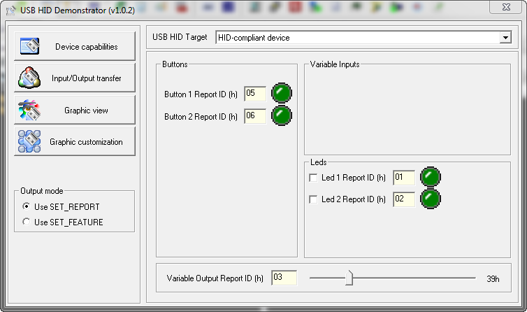
The project supports interaction with the USB HID Demonstrator utility from ST Microelectronics.
The Device capabilities page displays the capabilities described in the Report Descriptor.
Input / Output transfer allows you to manually send data to the device and see the package that comes from it.
Graphic view allows you to control LEDs, Led 1, Led 2 checkboxes by setting the corresponding Report ID, as well as transfer a byte with the slider (ReportID = 3)
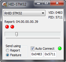
I also wrote a small demo software that automatically determines the connection to the computer and the disconnection of our device by its VID and PID, displays the status - connected / disconnected by the indicator next to the Auto Connect checkbox
Radio Send Send allows you to select the method for sending data to the device.
Report: displays the packet received from the device byte-by-byte, starting with the ReportID.
Clicking on the LEDs below - control the LEDs of the device. Their status displays the current state of the device. Read from the report from the device.
Moving the slider, we send the Report with ID = 3 and the value corresponding to the position of the slider. The device will return this value in 4 byte report.
In the dropdown combo box, the HID devices found in the system are displayed, and if our device is found, its name is displayed.
Download everything you need on GitHub . Composed of:
DT - HID Descriptor tool
tstHID-STM32F103 - project for EmBlocks
USB HID Demonstrator - utility from ST Microelectronics
HIDSTM32.exe - my Delphi demo soft on a similar feature, but not requiring configuration
If you have any questions - write in the comments. I will try to answer. I tried not to drown the essence in a heap of trifles in order to develop a common understanding. The rest can already be understood by studying the project. But if you need to quickly make your device, and there is no time to climb into the jungle - I described everything that you need.
PS By default, when the host goes into power saving mode, the device goes to sleep with it, and if you connect the device to a sleeping PC, it will also go into a slip. Therefore, if we just plug the power supply into the device or are powered from the battery, then it will not work, considering that it is connected to the sleeping PC (configuration packages will not come from the power supply exactly). I changed the library so that the device worked and when I connected, just the BP. Therefore, the device will work both when connected to a PC and autonomously. (It took me a long time to figure it out.)
Source: https://habr.com/ru/post/208026/
All Articles