Siemens Logo! - ten years later
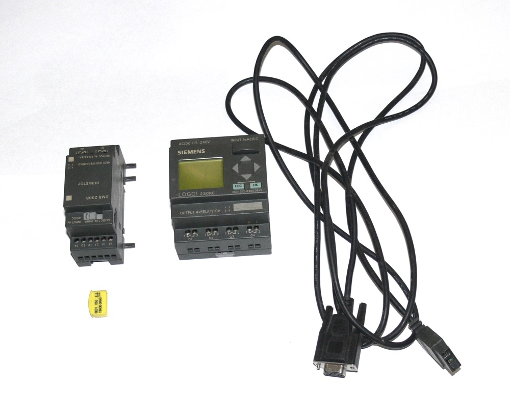
Restoring order in the closet, I found the old controller Siemens Logo! and a number of accessories to it. Once, ten years ago, I made several projects on such toys. Nostalgia and fond memories of those times led me to write this post.
There are many photos under the cut (geek porn)!
')
So what is Siemens Logo !? Siemens is positioning this device as an "intelligent relay" that allows you to build simple automation systems. Examples of such systems include, for example, garage doors, stair lighting, control of pumps that support the water level in the tank and other simple systems that include several sensors with discrete outputs, several actuators and controls (buttons and switches). Sensors with analog outputs are also supported, if there are special expansion modules.
Siemens Logo Family! includes many different modules, but the most important of them is the processor module.
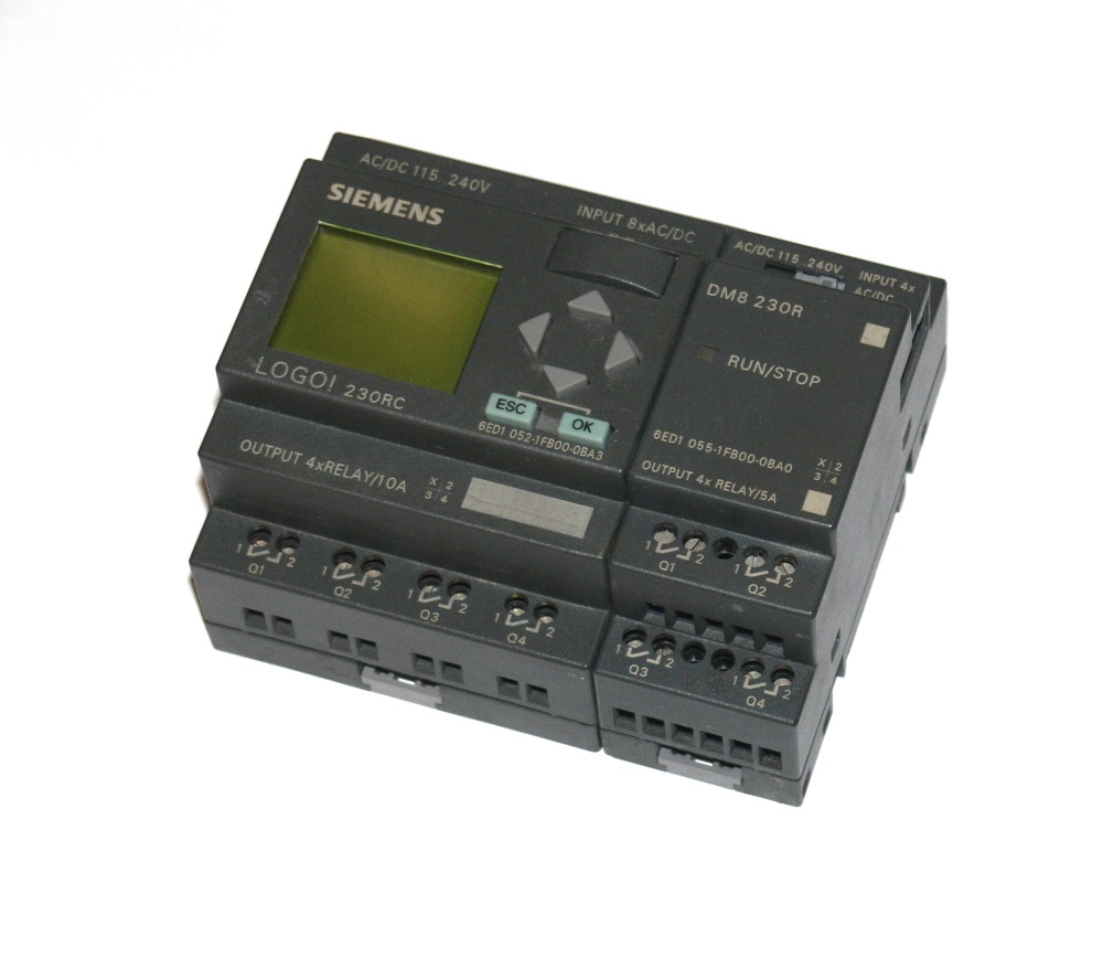
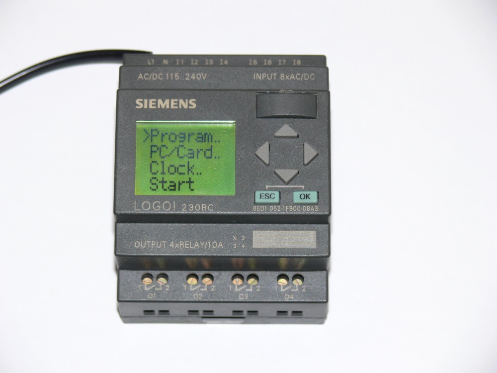
The module that I want to show you is equipped with a small monochrome LCD. It displays the menus needed when the program is loaded, messages may appear on it when the program is running, you can even, with a strong desire, program the controller without being connected to a computer. Blind modules (Pure) that do not have a screen are also produced, but if you are building systems on Siemens Logo !, you need to have at least one module with a screen in order to be able to copy memory modules. But this will be discussed below.
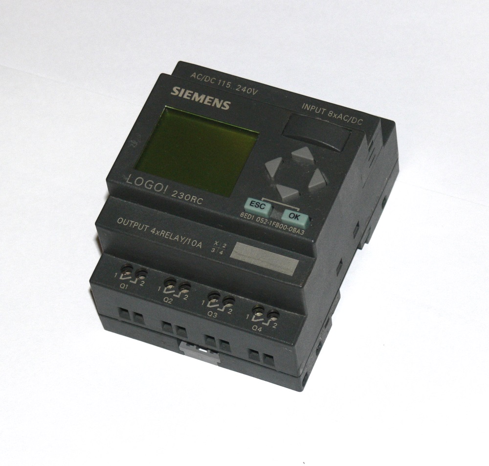
So, the processor module 0BA3 is powered by 220V, and has four discrete outputs (relays) and eight discrete inputs. The discrete output is a relay with a load capacity of up to 10A at a voltage of up to 240V, the discrete input allows the connection of 220V AC circuits.
The most interesting, of course, inside. So, the processor module disassembled:
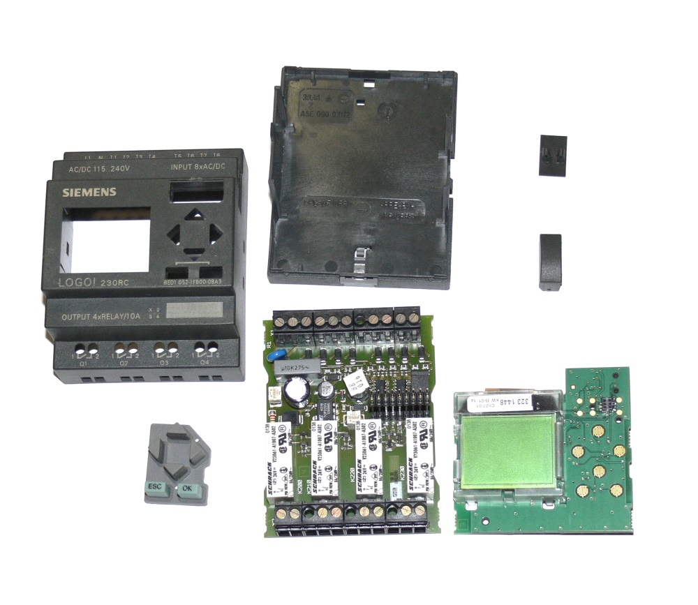
The module consists of two boards, the processor itself and the LCD are located on the top board, the power supply, relays and discrete inputs are on the bottom board.
Let's start with the top board.

Top board, top side.
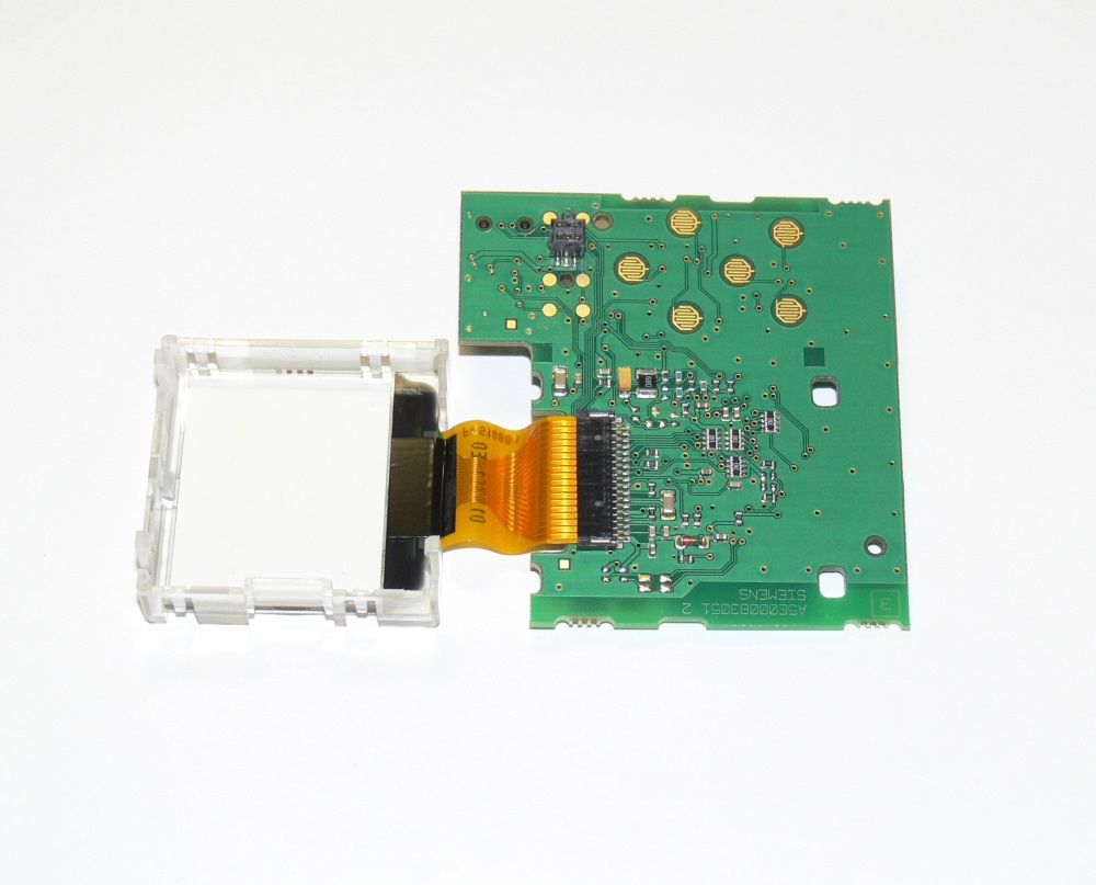
The same with the removed LCD.
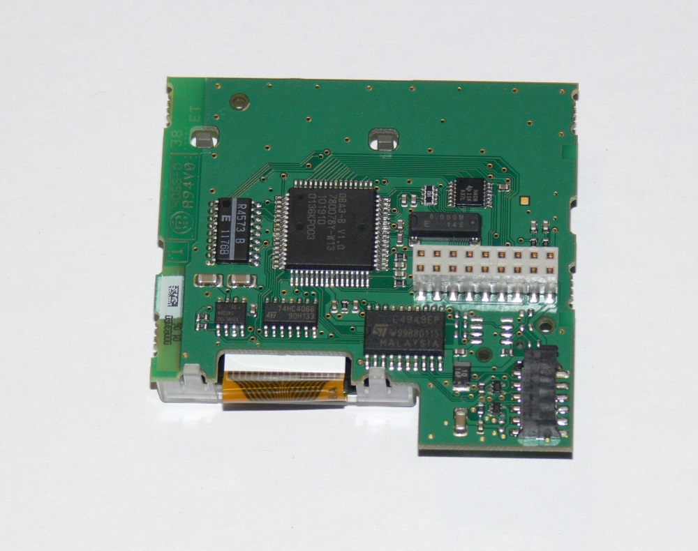
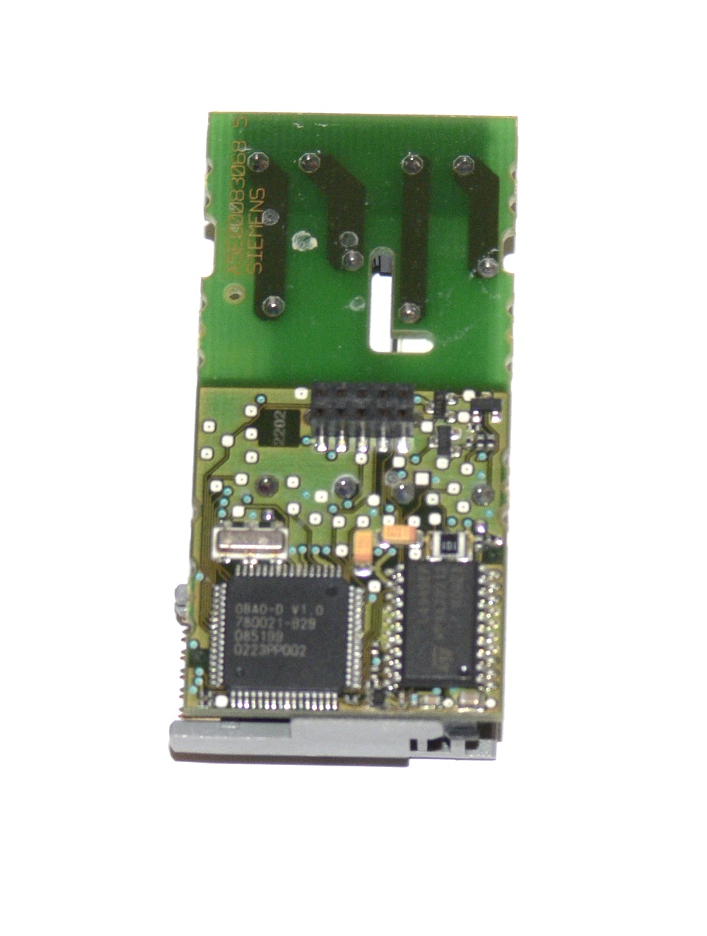
Top board, bottom side.
On the top board is the processor itself (ASIC, designed specifically for this product), LCD, L4949EP chip (5V voltage regulator, reset circuit and power supervisor), 8 MHz quartz, another chip of unknown purpose, Atmel 24C08 chip (8 kbit EEPROM ), microcircuits 74hc4066 (4 analog keys) and 74HC11 (?). Also on the top board are connectors for connecting the bottom board, expansion module and memory module.
As you can see, there is nothing particularly interesting on the top board. All main functionality consists in one specialized microcircuit.
On the bottom board, we see more interesting things. Here is the power supply on the TOP332G chip. The microcircuit itself (switching power supply controller) is very common, but here it is used in a somewhat unusual turn on, without a transformer. It turns out a simple step-down pulse voltage converter, lowering the voltage from the mains (85 - 240V) to 24V DC. The power supply does not isolate the device from the network! Digital "ground" and the common wire of discrete inputs are connected to the "zero" network directly, so when installing the controller it is important, for the sake of safety, to connect the network correctly, taking into account which wire is zero and which is phase.
The discrete outputs are a Schrack relay with 24V winding. By the way, the marking on the case of the relay states that the switching current is 8A, and Siemens declares 10A for this module. Disorder.
Discrete inputs are not electrically isolated. In fact, the mains voltage through the divider and the filter goes directly to the logic.

Discrete input circuit
Also on the bottom board are screw terminals, a connector for connecting to the top board, and a piezo squeaker.
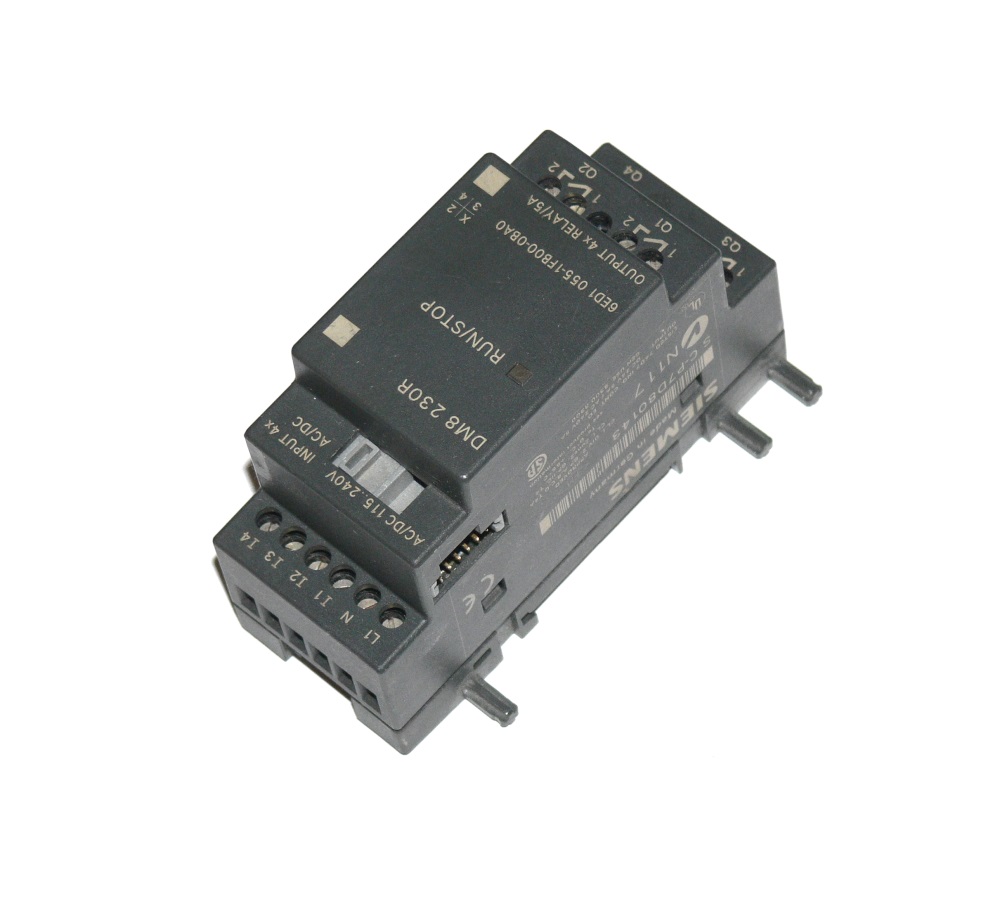
The discrete I / O module 0BA0 contains four discrete outputs (relays), four discrete inputs, and, like the other modules of this family, is attached to the processor module from the side.
Separately, it looks like this:
And disassembled:
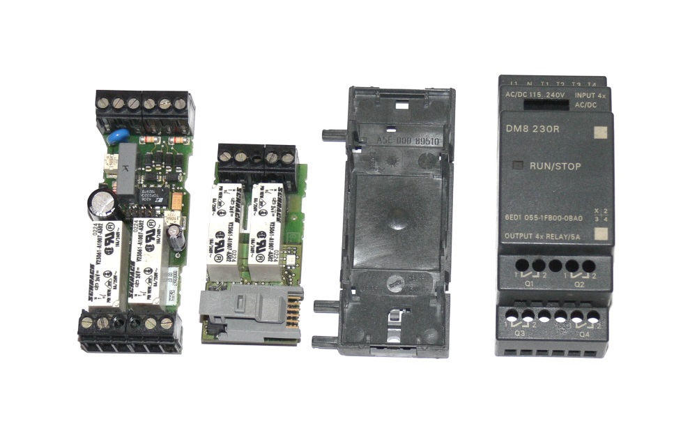
It also consists of two boards, top and bottom.

Top board, top view.
The same Schrack relays at 8A are used, but this time Siemens claims a maximum current of 5A. That is, in the case of the processor unit, they risk that the maximum permissible current through the relay contacts will be exceeded, and here they are reinsured.
Top board, bottom view.
Here again we see a specialized microcircuit and the power supply stabilizer L4949 already familiar to us.

The bottom board contains two more relays, a power source and four discrete inputs. All these nodes are similar to those used in the processor module.
The cable is designed to download programs through the RS-232 port. The cable is electrically isolated.

Let's see what's inside.
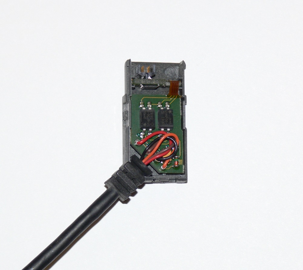
Inside flex-rigid PCB. On one side are two optocouplers.

Chip MAX3221 (RS232 port) and the buffer (74NS14 or some equivalent).
The little yellow thing in the photo is a memory module. Basically, Logo! it works without it, but the yellow module allows you to copy programs. After the program is poured into the controller via cable, it can be copied into the yellow module and inserted into another controller, say, located on the object. This is convenient because the installer does not need to take a laptop and cable with you. There are still red modules, they do not allow copying their contents into the internal memory of the controller (such as copy protection).
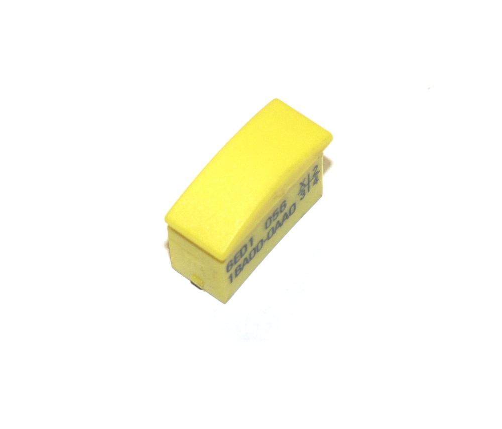
Inside there is an Atmel 24C08 EEPROM chip, the same as in the processor module.
So, we connect the power, turn on the controller, and see the following:
We write the program "flashing LED". LED in quotes, because in fact there is no indication of output triggering. We'll just hear the sound of the triggering relay. The word "write" can also be put in quotes, because the programs for Siemens Logo! not written, but drawn in a graphic environment Logo! Comfort.
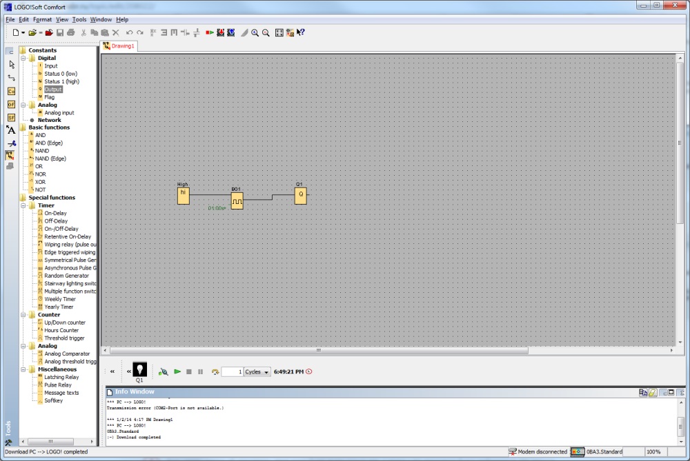
“Programs” in this environment are built of “cubes”, each of which is a logical element, time relay, input, output, etc.
In the same environment, you can run a simulation program. In our case, the program consists of one Symmetrical Pulse Generator block, one discrete output, and one constant (log. 1) allowing the generator to work. Everything is very simple.
The software allows you to program any generation of Logo! Controllers, both old (this, for example, the third model), and new (6th and 7th model). They differ in that the new features have much more, and much less restrictions. The third model, for example, will allow to use in the program only up to 56 blocks, in modern models of blocks there can be 200.
The advantage of this environment is that you can start work from scratch in it, without having experience programming logic controllers. The “learning curve” is minimal and can take one evening.
The software is well documented, there are examples of projects (for example, automation of stair lighting).
Now the fun part.
Of course, it is these models that have long been outdated and discontinued, so I’ll quote the prices of their modern incarnations.
Prices are in rubles and are approximate.
Processor Module - 4200 p.
Discrete I / O Module - 3000 p.
Cable - 3800 r.
Memory module - 650 p.
Impressive, isn't it? Especially on the cable (two chips and two optocouplers) and a memory module (one chip costing less than 10 p.)
That's all. Hope you enjoyed it. I will be glad to answer your questions.
There are many photos under the cut (geek porn)!
')
So what is Siemens Logo !? Siemens is positioning this device as an "intelligent relay" that allows you to build simple automation systems. Examples of such systems include, for example, garage doors, stair lighting, control of pumps that support the water level in the tank and other simple systems that include several sensors with discrete outputs, several actuators and controls (buttons and switches). Sensors with analog outputs are also supported, if there are special expansion modules.
1. Iron
Siemens Logo Family! includes many different modules, but the most important of them is the processor module.
1.1. Processor module
The module that I want to show you is equipped with a small monochrome LCD. It displays the menus needed when the program is loaded, messages may appear on it when the program is running, you can even, with a strong desire, program the controller without being connected to a computer. Blind modules (Pure) that do not have a screen are also produced, but if you are building systems on Siemens Logo !, you need to have at least one module with a screen in order to be able to copy memory modules. But this will be discussed below.
So, the processor module 0BA3 is powered by 220V, and has four discrete outputs (relays) and eight discrete inputs. The discrete output is a relay with a load capacity of up to 10A at a voltage of up to 240V, the discrete input allows the connection of 220V AC circuits.
The most interesting, of course, inside. So, the processor module disassembled:
The module consists of two boards, the processor itself and the LCD are located on the top board, the power supply, relays and discrete inputs are on the bottom board.
Let's start with the top board.
Top board, top side.
The same with the removed LCD.
Top board, bottom side.
On the top board is the processor itself (ASIC, designed specifically for this product), LCD, L4949EP chip (5V voltage regulator, reset circuit and power supervisor), 8 MHz quartz, another chip of unknown purpose, Atmel 24C08 chip (8 kbit EEPROM ), microcircuits 74hc4066 (4 analog keys) and 74HC11 (?). Also on the top board are connectors for connecting the bottom board, expansion module and memory module.
As you can see, there is nothing particularly interesting on the top board. All main functionality consists in one specialized microcircuit.
On the bottom board, we see more interesting things. Here is the power supply on the TOP332G chip. The microcircuit itself (switching power supply controller) is very common, but here it is used in a somewhat unusual turn on, without a transformer. It turns out a simple step-down pulse voltage converter, lowering the voltage from the mains (85 - 240V) to 24V DC. The power supply does not isolate the device from the network! Digital "ground" and the common wire of discrete inputs are connected to the "zero" network directly, so when installing the controller it is important, for the sake of safety, to connect the network correctly, taking into account which wire is zero and which is phase.
The discrete outputs are a Schrack relay with 24V winding. By the way, the marking on the case of the relay states that the switching current is 8A, and Siemens declares 10A for this module. Disorder.
Discrete inputs are not electrically isolated. In fact, the mains voltage through the divider and the filter goes directly to the logic.
Discrete input circuit
Also on the bottom board are screw terminals, a connector for connecting to the top board, and a piezo squeaker.
1.2. Discrete I / O Module
The discrete I / O module 0BA0 contains four discrete outputs (relays), four discrete inputs, and, like the other modules of this family, is attached to the processor module from the side.
Separately, it looks like this:
And disassembled:
It also consists of two boards, top and bottom.
Top board, top view.
The same Schrack relays at 8A are used, but this time Siemens claims a maximum current of 5A. That is, in the case of the processor unit, they risk that the maximum permissible current through the relay contacts will be exceeded, and here they are reinsured.
Top board, bottom view.
Here again we see a specialized microcircuit and the power supply stabilizer L4949 already familiar to us.
The bottom board contains two more relays, a power source and four discrete inputs. All these nodes are similar to those used in the processor module.
1.3. Boot cable
The cable is designed to download programs through the RS-232 port. The cable is electrically isolated.
Let's see what's inside.
Inside flex-rigid PCB. On one side are two optocouplers.
Chip MAX3221 (RS232 port) and the buffer (74NS14 or some equivalent).
1.4. Memory module
The little yellow thing in the photo is a memory module. Basically, Logo! it works without it, but the yellow module allows you to copy programs. After the program is poured into the controller via cable, it can be copied into the yellow module and inserted into another controller, say, located on the object. This is convenient because the installer does not need to take a laptop and cable with you. There are still red modules, they do not allow copying their contents into the internal memory of the controller (such as copy protection).
Inside there is an Atmel 24C08 EEPROM chip, the same as in the processor module.
2. We write the program
So, we connect the power, turn on the controller, and see the following:
We write the program "flashing LED". LED in quotes, because in fact there is no indication of output triggering. We'll just hear the sound of the triggering relay. The word "write" can also be put in quotes, because the programs for Siemens Logo! not written, but drawn in a graphic environment Logo! Comfort.
“Programs” in this environment are built of “cubes”, each of which is a logical element, time relay, input, output, etc.
In the same environment, you can run a simulation program. In our case, the program consists of one Symmetrical Pulse Generator block, one discrete output, and one constant (log. 1) allowing the generator to work. Everything is very simple.
The software allows you to program any generation of Logo! Controllers, both old (this, for example, the third model), and new (6th and 7th model). They differ in that the new features have much more, and much less restrictions. The third model, for example, will allow to use in the program only up to 56 blocks, in modern models of blocks there can be 200.
The advantage of this environment is that you can start work from scratch in it, without having experience programming logic controllers. The “learning curve” is minimal and can take one evening.
The software is well documented, there are examples of projects (for example, automation of stair lighting).
Now the fun part.
Prices.
Of course, it is these models that have long been outdated and discontinued, so I’ll quote the prices of their modern incarnations.
Prices are in rubles and are approximate.
Processor Module - 4200 p.
Discrete I / O Module - 3000 p.
Cable - 3800 r.
Memory module - 650 p.
Impressive, isn't it? Especially on the cable (two chips and two optocouplers) and a memory module (one chip costing less than 10 p.)
That's all. Hope you enjoyed it. I will be glad to answer your questions.
Source: https://habr.com/ru/post/208022/
All Articles