Measuring the current-voltage characteristics of the transistor using a Cypress microcontroller
Step 1: Source Materials
From the raw materials at home were:
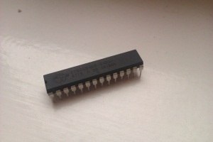
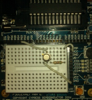
1. Cypress “CY8C29466 - 24PXI" microcontroller and “PSoCEVAL1 RevE” debug board

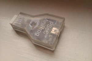
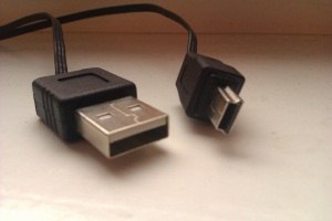
2. PSoC MiniProg programmer and USB-miniUSB wire for it
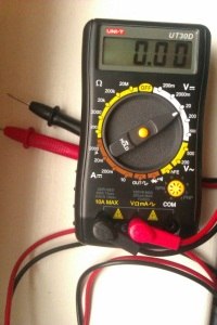
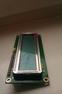
3. Multimeter and LCD display (very useful when debugging)
Step 2: Wiring Diagram
First of all it was necessary to estimate the switching circuit. I recall that the task is to measure the current-voltage characteristics of the field-effect transistor. Namely, the dependence of ICI (drain-source current) on the voltage UZ (at the gate). Since usually analog-digital converters are tied to voltage measurements, a circuit was needed to indirectly measure the current from a known voltage. And after a small discussion, the following scheme appeared.
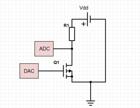 Where:
Vdd - supply voltage of the microcontroller and board
R1 - workload
Q1 - field effect transistor
DAC and ADC are digital-analog and analog-digital converters, respectively.
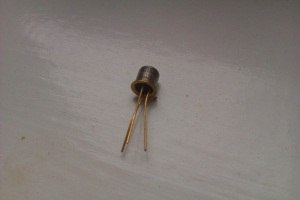
Step 3: Transistor Selection
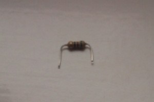
It was found in the manuals that the board voltage is Vdd = 5V, and the working range of the digital-to-analog converter ranges from about 0 to 5V. Based on this data, a transistor (Q1) and operating resistances (R1) were selected. The choice fell on the KP103M and a resistance of 50 Ohms.
Technical characteristics of the KP103M transistor:
• Transistor structure: with pn-junction and p-channel;
• max - Dissipated power drain-source: 120 mW;
• Uzi from - transistor cutoff voltage - voltage between the gate and the source: 2.8 ... 7 V;
• Usi max - Maximum drain-source voltage: 10 V;
• IC nach - Initial drain current: 3 ... 12 mA;
• S - The steepness of the characteristics: more than 1.3 ... 4.4 mA / V;
• 11 - Transistor input capacitance - capacitance between the gate and the source: 20 pF;
• 12 - Feedback capacitance in the circuit with a common source in case of a short circuit at the AC input: 8 pF;
• Ksh - Transistor noise figure: no more than 3 dB at 1 kHz.
')
Half a day on the market and the following things were bought.
1. Field-effect transistor KP103M and operating resistance 50 Ohm
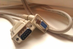
2. RS 232 cable, useful for transporting data to a computer (I wanted to buy RS232-USB but the price played its role, and even was afraid to work with virtual com ports)
Step 4: Programming the microcontroller.
0. Introduction
Programming in the PSoC Designer 5.3 environment is carried out at a sufficiently high level (although it is impossible to call it with programming, this is something between programming and modeling). The main environment working space is a chip layout. On which are the free blocks (and if you have already added something that is not free) to install the modules of the microcontroller. These can be various DACs, ADCs, display controllers, data transceivers, programmable amplifiers, timers, counters, temperature sensors (meaning built-in microchips), user blocks, and so on. Digital modules are located in the upper part of the workspace, analogue in the lower. The working area also includes tires, on which the inputs and outputs of analog and digital modules are hung, which in turn are connected to ports (the so-called microcontroller legs). By simply pulling and clicking the mouse, you can install any of the modules and tie it to the ports, provided that there is a free position for it.

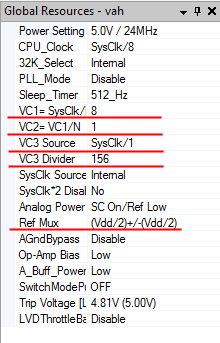
In the main working tab there is also an important panel “Global resources”. In which, the main performance characteristics of the chip are located, such as: operating frequency, power mode, some global variable frequency dividers, necessary for the operation of some digital and analog blocks.
Red highlighted the properties that have been changed in the course of the work. Ref Mux is the voltage range for analog chip units. VC are the system dividers of the clock frequency of the microcontroller processor; they are needed for synchronized operation of digital blocks and D / A converter blocks.
1. DAC
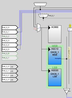
The first step was to install a DAC8 module on the microcontroller (which means 8bit Digital-to-Analog Converter), which means an 8-bit digital-to-analog converter. The bit width of 8m bits means that the smallest unit of voltage change will be (Vmax-Vmin) / 256, for our case 5V / 256. Accuracy to measure is more than enough. The output of the DAC was mapped to the AnalogOutBus_0 bus. And the bus itself is displayed on one of the free ports of the controller, my DAC is displayed on Port_0_3, alas, it is not visible in the screenshot, but check my word, it is there. Thus, it turned out about the following picture.
Next, it was necessary to write a small code to run the microcontroller and DAC'p. An important note is that the device supports C and Assembly.
#include <m8c.h> // part specific constants and macros #include "PSoCAPI.h" // PSoC API definitions for all User Modules void main(void) { DAC8_1_Start(DAC8_1_HIGHPOWER); M8C_EnableGInt ; // Uncomment this line to enable Global Interrupts while(1) { DAC8_1_WriteBlind(255);// 0 255 8 0 5 } } We collect fee in accordance with the scheme given in step 2.
We flash the microcontroller. Debug tester, with different values of the function DAC8_1_WriteBlind (); if the indicators are adequate and linearly dependent, go ahead and deal with the DAC unit.
2. ADC
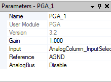
Not to say that DAC'om things went much easier. To implement it, it took as many as 3 microcontroller modules. First, it is a PGA (Programmable Gain Amplifier), a programmable opamp. It is needed not so much for amplification (to be honest, the gain in it is set to 1, and besides, it is not capable of delivering voltages higher than the supply voltage), but rather to increase the input resistance. Whatever the value of the current in the circuit does not affect the accuracy of the measurement. One entrance, which was plugged into the ground, and the second hung on port_0_1. The second module itself became the DAC itself, the full name of the element ADCINC12. The bit width, which is 12bit, is 4096 quantization steps on the input signal. One of the inputs of the DAC'pa was connected to the PGA output, the second is connected to the ground by default. It should also be noted that all these things (including DAC'ka) for synchronous work, should sit on a single clock generator, or to be more precise, a processor clock divider. Analog blocks are planted on the VC1 clock divider equal to SysClock / 8 (24 MHz / 8). All the above has approximately the following form.

The last module, about which they haven't said anything yet, is the LCD module, an interface for working with the display. And we need it to debug the work of ADC and PGA, since we cannot check the correctness of the operation of these modules from outside. Fortunately, it does not occupy space on the working scheme, and from the settings it has only one parameter, LCDPort, we need Port_2, which is already on our debug board.
In case I missed something, I’ll give screenshots of the settings of the above described blocks.


Modifying the code:
#include <m8c.h> // part specific constants and macros #include "PSoCAPI.h" // PSoC API definitions for all User Modules void main(void) { DAC8_1_Start(DAC8_1_HIGHPOWER); PGA_1_Start(PGA_1_HIGHPOWER); ADCINC12_1_Start(ADCINC12_1_HIGHPOWER); ADCINC12_1_GetSamples(0); // - LCD_Start(); LCD_Position(1,0); // M8C_EnableGInt ; // Uncomment this line to enable Global Interrupts while(1) { DAC8_1_WriteBlind(255);// 0 255 8 0 5 result = ADCINC12_1_iGetData() + 2048; ADCINC12_1_ClearFlag(); LCD_Position(1,0); LCD_PrHexInt(result); } } The screen has numbers in the range from 0 to 0x0FFF, depending on the applied voltage. Hurray! Everything is working fine. Moving on.

3. UART
UART is a data transfer protocol. Best known for RS232 interface. It was necessary to pull the UART block onto the circuit. The UART module occupies two digital blocks, one for the RX receiving line, the second for the TX, the transmitting line. The outputs of these units were connected to specific ports specifically designated for data transport. Port_2_7 for exit, Port_1_6 for login. The UART device should operate on the VC3 = SysClock / 156 clock generator, thereby allowing data to be transmitted with a bit rate of 19200. The UART_1_PutSHexInt () function will be used for transmission.
Finally, the final touch was a change from the infinite loop to the while (i <255). To be able to vary the values supplied to the DAC and each time remove the new voltage.
The final version of the code for the microcontroller looks like this:
The final version of the code
//---------------------------------------------------------------------------- // C main line //---------------------------------------------------------------------------- #include <m8c.h> // part specific constants and macros #include "PSoCAPI.h" // PSoC API definitions for all User Modules int result; int i; void main(void) { DAC8_1_Start(DAC8_1_HIGHPOWER); PGA_1_Start(PGA_1_HIGHPOWER); ADCINC12_1_Start(ADCINC12_1_HIGHPOWER); ADCINC12_1_GetSamples(0); LCD_Start(); LCD_Position(1,0); UART_1_Start(UART_PARITY_NONE); M8C_EnableGInt ; // Uncomment this line to enable Global Interrupts while(i<255) { DAC8_1_WriteBlind(i); if(ADCINC12_1_fIsDataAvailable() != 0) { result = ADCINC12_1_iGetData() + 2048; ADCINC12_1_ClearFlag(); LCD_Position(1,0); LCD_PrHexInt(result); UART_1_PutSHexInt(result); /* Print result to UART */ i++; } } } Step 5: Interception of the COM port

How to check whether data is actually coming to the computer? First you need to check whether the com-port is turned on and whether your computer is running. For windows 7 -> the right button My Computer -> Device Manager -> and we should see the picture to the right of the text. If this does not happen, the com port is most likely disabled, and it should be enabled in the BIOS.
Now you need to configure it.
We set the fields
Bit per second - 19200
Data bits - 8
Parity - None
Stop bits - 1
Flow control - none

Download the program HyperTerminal or something similar, maybe even have something standard. Run it. Choose our port COM1.
And we get crazy byte sequences.

The transmitter works.
Step 6: C # client
Run any VisualStudio C #. Create a console application. Add there two classes. One to work with Com is another with Excel (I called them that way). Add a library to work with Excel (right-click References -> Add Reference ... -> Extensions -> Microsoft.Office.Interop.Excel) to the project. All conversions from Hex to int and from int to current will be done in Program.cs.
Program.cs
class Program { public static List<double> ConvInToAmp(List<int> input) { List<double> converted = new List<double>(); double stap = 0.00116822; double Vdd = 4.8; double R = 50; for (int i = 0; i < 255; i++) { converted.Add(input[i] * stap); converted[i] = Vdd - converted[i]; converted[i] = converted[i] / R; //Console.WriteLine(converted[i]); } return converted; } public static List<double> CreateVolt() { List<double> volts = new List<double>(); double stap = 0.0188235294117647; for (int i = 0; i < 255; i++) { volts.Add(i*stap); } return volts; } static void Main(string[] args) { Com port = new Com(); port.Strart(); while (!port.Full()) ; port.Stop(); Console.WriteLine("Data transmission complite"); List<int> input = port.GetData(); List<double> converted = ConvInToAmp(input); Console.WriteLine("Conversin complite"); Excel exel = new Excel(CreateVolt(), converted); Console.Read(); } } Com.cs
class Com { private List<int> values = new List<int>(); private SerialPort port = new SerialPort("COM1", 19200, Parity.None, 8, StopBits.One); private void received(object sender, SerialDataReceivedEventArgs e) { string buf; buf = port.ReadExisting(); while (!String.IsNullOrEmpty(buf)) { string str = buf.Substring(0, 4); int v = Convert.ToInt32(str, 16); buf = buf.Remove(0, 4); Console.WriteLine(v); values.Add(v); } } public void Strart() { Console.WriteLine("Incoming data:"); port.DataReceived += new SerialDataReceivedEventHandler(received); port.Open(); } public void Stop() { port.Close(); } public bool Full() { if (values.Count == 255) return true; else return false; } public List<int> GetData() { return values; } }<source lang="cs"> Excel.cs
class Excel { private List<double> xScale; private List<double> yScale; private Application exApp = new Application(); private Sheets sheets; private Worksheet worksheet; private Range range; public Excel(List<double> x,List<double> y) { xScale = x; yScale = y; exApp.Visible = true; exApp.SheetsInNewWorkbook = 1; exApp.Workbooks.Add(Type.Missing); sheets = exApp.Worksheets; worksheet = (Worksheet)sheets.get_Item(1); for (int i = 1; i < 255; i++) { range = worksheet.get_Range("A" + Convert.ToString(i), "A" + Convert.ToString(i)); range.Value = xScale[i]; range = worksheet.get_Range("B" + Convert.ToString(i), "B" + Convert.ToString(i)); range.Value = yScale[i]; } ChartObjects chartObjs = (ChartObjects)worksheet.ChartObjects(); ChartObject chartObj = chartObjs.Add(150, 20, 700,500); Chart xlChart = chartObj.Chart; xlChart.ChartType = XlChartType.xlXYScatterLinesNoMarkers; //PlotArea. Range xValues = worksheet.Range["A1", "A254"]; Range values = worksheet.Range["B1", "B254"]; SeriesCollection seriesCollection = xlChart.SeriesCollection(); Series series1 = seriesCollection.NewSeries(); series1.MarkerSize = 3; series1.XValues = xValues; series1.Values = values; } } } If everything is correctly written and done, the client will write that he accepts the data and at the end will display the graph in Excel.

Source: https://habr.com/ru/post/208016/
All Articles