Bresenham algorithm in real-time applications - part two
Continuation of the post " Brezenham algorithm in real-time applications ."
Recall that we are writing an output program for laser scanners.

In my case, the laser scanner is used on the installation of the so-called laser stereolithography , where the drawing is a ray of ultraviolet laser on the surface of the liquid photopolymer. You cannot see ultraviolet with your eyes, but you can see harmonics (radiation of relatively low power in the visible range, which is generated in a laser at a wavelength not important to it), as well as fluorescence from a photopolymer or plain white coated paper.
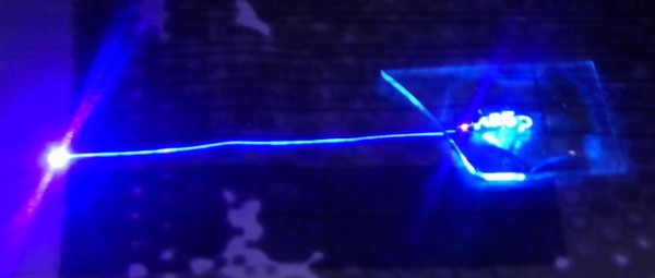
Here in the picture - coated paper, slightly soaked with photopolymer, on the cover glass is applied a layer of photopolymer about 1 mm thick, on which is drawn, as you can see, a favorite word on Habré. On the left is the “point of sludge” where the beam goes after drawing. The trace between the drawing and the sludge point is an idle transfer of the beam, which we see only due to the considerable afterglow of the fluorescence of the paper. In terms of the algorithm discussed earlier, this transfer can be represented as a sequential execution
We will not see any “zigzags” or “loops” in a good scanner. At least - by the eye.
')
Although if there is a source of electro-magnetic interference such as a mobile phone nearby, it could be
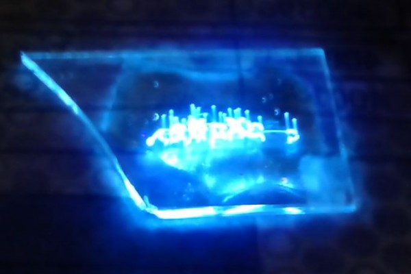
Without coated paper, we won't see any idle rolls.
We now return to our algorithm. In the comments to the first part, no one guessed what we will see as a result of the implementation of the proposed implementation of the Brezenham algorithm.
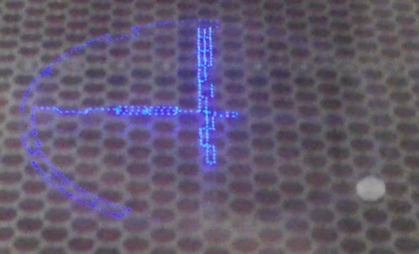
And we will see just such a thing
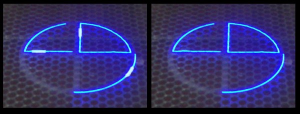
On the left, what we see (this is photoshop, the conscience did not allow the wrong program to be poured into the controller), on the right, what we expected to see.
Short bright lines indicate that the scanning speed sometimes decreases. How can it be reduced if we do not have any multitasking in the controller and the operating system in general? Very simple - we have interruptions! Even if the controller is not loaded with any other functions, except for issuing to DACs, we still have interruptions related to communication with the control computer. For example, through a UART (COM port) or Ethernet. It seems that not so much time is taken by interruptions and it seems that not so often we do a survey. Dashes can be shorter, turning into points, but it is impossible to get rid of them completely with such a realization of delay
Often delays in programming microcontrollers are done on a simple counter.
Cheap andangry wrong. In the case of an interruption, such a realization of the delay will never know that the program “went away” to another place and the required time has passed. Ideologically more correct latency uses hardware timer timer
In this case, the delay function automatically learns about the interruption that has occurred, although it does not guarantee the absolute accuracy of the processor. If the program spends most of the time in delays this could be limited, however, for the case of fast movements, the use of a hardware timer should be end-to-end
Note that in this variant, both different times for output to a DAC for one channel or two channels are automatically taken into account, as well as the spread of output time, if output is used until it is ready.
In this implementation, possible interrupts are taken into account inside the Line () function; outside this function, the effect of interruptions on the execution duration can still manifest itself. I hope that the reader will not be difficult to guess how to proceed in the general case.
And finally - if you find yourself with the program, you can see the most unexpected squiggles instead of the expected test circle and square.

In this case, “everything almost worked”, only incomprehensible teeth appeared. As it turned out, one line y + = sy; was replaced by x + = sx; . By the way, due to a randomly hit touchpad on a laptop.
Recall that we are writing an output program for laser scanners.
In my case, the laser scanner is used on the installation of the so-called laser stereolithography , where the drawing is a ray of ultraviolet laser on the surface of the liquid photopolymer. You cannot see ultraviolet with your eyes, but you can see harmonics (radiation of relatively low power in the visible range, which is generated in a laser at a wavelength not important to it), as well as fluorescence from a photopolymer or plain white coated paper.
Here in the picture - coated paper, slightly soaked with photopolymer, on the cover glass is applied a layer of photopolymer about 1 mm thick, on which is drawn, as you can see, a favorite word on Habré. On the left is the “point of sludge” where the beam goes after drawing. The trace between the drawing and the sludge point is an idle transfer of the beam, which we see only due to the considerable afterglow of the fluorescence of the paper. In terms of the algorithm discussed earlier, this transfer can be represented as a sequential execution
putXY(x,y, wait); // , x=32000, y=32000 putXY(x0,y0, wait); // y, x0=100, y0=100 - We will not see any “zigzags” or “loops” in a good scanner. At least - by the eye.
')
Although if there is a source of electro-magnetic interference such as a mobile phone nearby, it could be
Without coated paper, we won't see any idle rolls.
We now return to our algorithm. In the comments to the first part, no one guessed what we will see as a result of the implementation of the proposed implementation of the Brezenham algorithm.
And we will see just such a thing
On the left, what we see (this is photoshop, the conscience did not allow the wrong program to be poured into the controller), on the right, what we expected to see.
Short bright lines indicate that the scanning speed sometimes decreases. How can it be reduced if we do not have any multitasking in the controller and the operating system in general? Very simple - we have interruptions! Even if the controller is not loaded with any other functions, except for issuing to DACs, we still have interruptions related to communication with the control computer. For example, through a UART (COM port) or Ethernet. It seems that not so much time is taken by interruptions and it seems that not so often we do a survey. Dashes can be shorter, turning into points, but it is impossible to get rid of them completely with such a realization of delay
void putpixel(int x, int y, int wait)) { outPortX(x); // X x outPortY(y); // Y y delay(wait); // wait } Often delays in programming microcontrollers are done on a simple counter.
void delay(int wait) // wait "" { int i; for(i=0;i<wait; i++); } Cheap and
void delay(int wait) { unsigned int t0; t0 = /LPC_TIM1->TC //LPC_TIM1->TC - LPC 17xx while(LPC_TIM1->TC - t0 < wait); } In this case, the delay function automatically learns about the interruption that has occurred, although it does not guarantee the absolute accuracy of the processor. If the program spends most of the time in delays this could be limited, however, for the case of fast movements, the use of a hardware timer should be end-to-end
/* real time Bresenham alg. implementation */ void Line(int x1, int y1, int x2, int y2, int wait) { int x1,y1,dx,dy,sx,sy,d,d1,d2; unsigned int t0 = LPC_TIM1->TC; int i, x,y; if( x2 >= x1) { dx = x2 - x1; sx = 1; } else { dx = x1 - x2; sx = -1; } if( y2 >= y1) { dy = y2 - y1; sy = 1; } else { dy = y1 - y2; sy = -1; } /****************************/ if(dy <= dx) { d = (dy << 1) - dx; d1 = dy << 1; d2 = (dy - dx) << 1; for(x=x1+sx,y=y1,i=1; i <= dx ; i++,x+=sx) { if(d > 0) { d += d2; y += sy; putXY(x,y,wait,&t0); } else { d += d1; putX(x, wait, &t0); } } } else { d = (dx << 1) - dy; d1 = dx << 1; d2 = (dx - dy) << 1; for(x=x1,y=y1+sy,i=1;i <= dy ; i++,y += sy) { if(d > 0) { d += d2; x += sx; putXY(x,y,wait, &t0); } else { d += d1; putY(y, wait, &t0); } } } /* endif(dy <=dx) */ } void putXY(int x, int y, int wait, unsigned int *pT0) { outPortXY(x,y); // X Y x y // #define outPortXY(x,y) outPortX(x); outPortY(y); /* wait */ while(LPC_TIM1->TC - *pT0 < wait); *pT0 += wait; } void putX(int x, int wait, unsigned int *pT0) { outPortX(x); // X x /* wait */ while(LPC_TIM1->TC - *pT0 < wait); *pT0 += wait; } void putY(int y, int wait, unsigned int *pT0) { outPortY(y); // Y y /* wait */ while(LPC_TIM1->TC - *pT0 < wait); *pT0 += wait; } Note that in this variant, both different times for output to a DAC for one channel or two channels are automatically taken into account, as well as the spread of output time, if output is used until it is ready.
In this implementation, possible interrupts are taken into account inside the Line () function; outside this function, the effect of interruptions on the execution duration can still manifest itself. I hope that the reader will not be difficult to guess how to proceed in the general case.
And finally - if you find yourself with the program, you can see the most unexpected squiggles instead of the expected test circle and square.
In this case, “everything almost worked”, only incomprehensible teeth appeared. As it turned out, one line y + = sy; was replaced by x + = sx; . By the way, due to a randomly hit touchpad on a laptop.
Source: https://habr.com/ru/post/207740/
All Articles