Glowing snowballs, or decorating the New Year with “improvised materials”
Inspired by the article about LEDs in the snow , I wanted to try to do something similar in my own. In the comments to that article, I published ideas and a small handful of photos. Even in spite of the fact that now there is snow in Moscow region is a scarce thing, this did not diminish the enthusiasm, rather the opposite - to realize the idea as soon as possible, while there is still snow.
The first attempt was a flask with a statically shining LED, but a little later the board was finished with a small slice of speakers.
')
How it works and how to do something similar - look under the cut.
PS "Podruzhnost" materials, most likely, applies to radio amateurs.
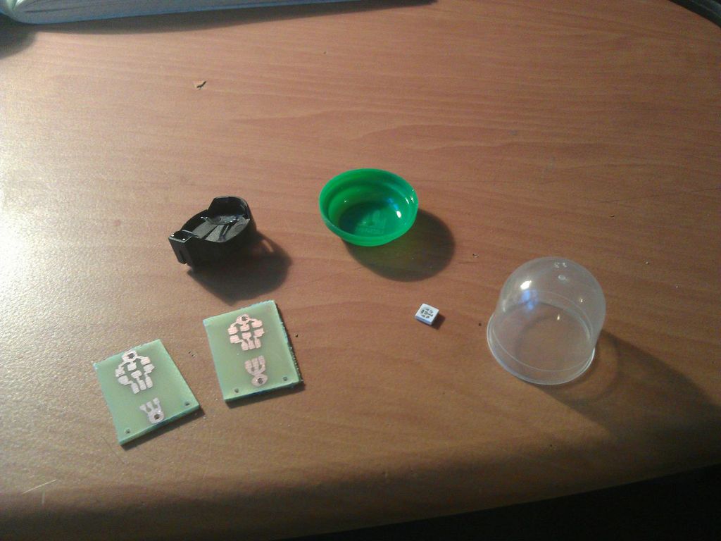
First we need:
The board is drawn elementary (I didn’t even bother to unscrew the printer, took out a marker for drawing on CDs and quickly scribbled it, and then immediately threw it into the solution, I didn’t have time to take a picture).
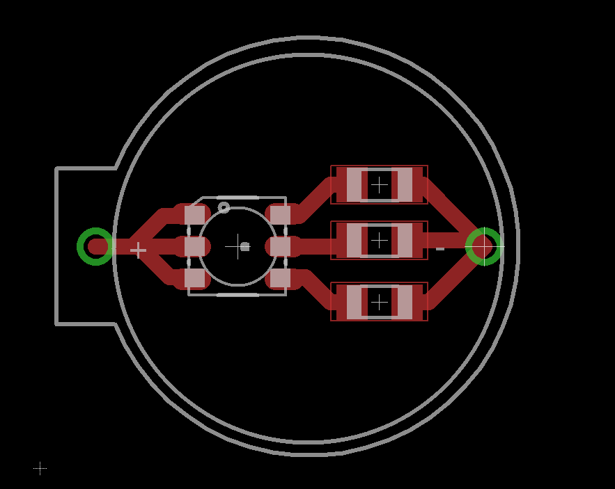
Here is the drawing board:
After etching, the board should be cut to the shape of a battery holder (the easiest way to do this is to pre-drill the holes and insert the holder at the back, then circle the holder with a marker. ATTENTION! Polarity matters! Watch the position of the holder’s ear!) And solder the LED, resistors and holder
Here is what comes out of it:

The board does not purposely solder one resistor, I wanted to get a purple glow, for this you need to turn on the red and blue channels by turning off the green one.
This is how the simplest lamp turns out. We cover the board with varnish (in fact, it is not necessary, but so the paths are less likely to darken), insert the battery, pack it in a flask and go to make snowballs!
As a programmer who breathes unevenly in the direction of any microcontroller technology, I decided to adapt a small chip to the business, which will bring a little more joy to this thing, causing the LED to glow beautifully in different colors.
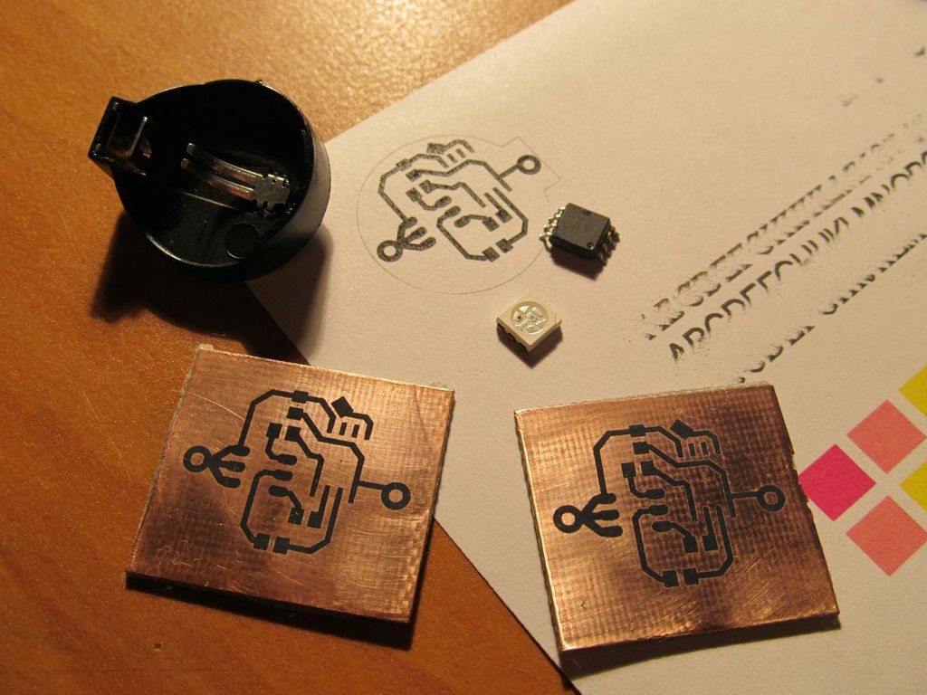
To do this, I took the Atmel ATtiny45 controller widely known in narrow circles (I wanted ATtiny13, but they were not suddenly in the box, the difference is only in the memory size. The program for this luminaire will fit in ATtiny13), I drew the board in Eagle and using laser-iron technology transferred the resulting picture to the foil textolite.
Compared with the previous version, a capacitor for a more stable power supply and the microcontroller appeared on the board. In terms of components, one has to manage with a little blood, since the space on the board is limited. I didn’t even provide a programming connector, I piped wires to the pins (especially for this, the LED channels were on the pins for programming, and I brought RESET to a separate platform). Resistors and capacitors on this board size 0805.
While the boards were being hounded, I started the program. In ATtiny45, the hardware output of the PWM signal is supported on PB0, PB1 legs and a few more. PB2 was not on this list. But the board is already drawn and etched, so I decided to make software PWM using the second timer (Timer1).
In order to make the luminaire more flexible in setting up, I applied such a mechanism. The chip has a ROM (EEPROM). In the first cell we will store the number that specifies the mode of operation. After each power up, we will increase this value by 1 and save it in the ROM. So, pulling the battery in the connector, you can switch modes of operation. In order not to miss the right one, I duplicated each mode (in fact, the next mode will turn on after two juggling of the battery).
Fuse bits can be counted here , I felt that 1 MHz is enough for me for comfortable PWM and for low power consumption. Generally speaking, fusion beats turned out to be standard for tiny45, so you can not change them.
I was already eager to try out a new craft in practice, because, having hurriedly sprinkled varnish from a can and letting it lie under the lamp for 5 minutes, I took it and ran out into the street with a camera (it was already quite late in the evening, just suitable conditions for testing).
And here is the result (the video does not differ from the one inserted above to attract attention):
Snowballs did not want to be molded at all, and yet I warmed up a handful of snow in my hands and everything turned out well!
For the idea of many thanks to Comrade. Kidar .
I posted all the materials on this project in Dropbox . When the time comes, I will prepare a separate makefile, and now after unpacking: make antares && make build, after which you can upload the images / antares.hex file to the chip in a convenient way.
Thanks for attention!
UPD: Updated archives with source files; Now, a complete PDF file for self-printing is included with the printed circuit board, and in the archive with the program is a hex file with ready-made firmware.
The first attempt was a flask with a statically shining LED, but a little later the board was finished with a small slice of speakers.
')
How it works and how to do something similar - look under the cut.
PS "Podruzhnost" materials, most likely, applies to radio amateurs.
How it all began
First we need:
- Transparent flask from the boot covers (can be taken at the nearest clinic)
- Holder for the battery type CR2032 (they are different, we need a clamp on the side)
- RGB LED (I used a planar, frame size 5050, dissipating)
- A few resistors (also planar, at 100 ohm - we will power from 3V - batteries)
- A piece of fiberglass with copper foil
- Copper sulfate or ferric chloride (or what else are you used to poison boards)
The board is drawn elementary (I didn’t even bother to unscrew the printer, took out a marker for drawing on CDs and quickly scribbled it, and then immediately threw it into the solution, I didn’t have time to take a picture).
Here is the drawing board:
After etching, the board should be cut to the shape of a battery holder (the easiest way to do this is to pre-drill the holes and insert the holder at the back, then circle the holder with a marker. ATTENTION! Polarity matters! Watch the position of the holder’s ear!) And solder the LED, resistors and holder
Here is what comes out of it:
The board does not purposely solder one resistor, I wanted to get a purple glow, for this you need to turn on the red and blue channels by turning off the green one.
This is how the simplest lamp turns out. We cover the board with varnish (in fact, it is not necessary, but so the paths are less likely to darken), insert the battery, pack it in a flask and go to make snowballs!
And then Ostap suffered
As a programmer who breathes unevenly in the direction of any microcontroller technology, I decided to adapt a small chip to the business, which will bring a little more joy to this thing, causing the LED to glow beautifully in different colors.
To do this, I took the Atmel ATtiny45 controller widely known in narrow circles (I wanted ATtiny13, but they were not suddenly in the box, the difference is only in the memory size. The program for this luminaire will fit in ATtiny13), I drew the board in Eagle and using laser-iron technology transferred the resulting picture to the foil textolite.
Compared with the previous version, a capacitor for a more stable power supply and the microcontroller appeared on the board. In terms of components, one has to manage with a little blood, since the space on the board is limited. I didn’t even provide a programming connector, I piped wires to the pins (especially for this, the LED channels were on the pins for programming, and I brought RESET to a separate platform). Resistors and capacitors on this board size 0805.
While the boards were being hounded, I started the program. In ATtiny45, the hardware output of the PWM signal is supported on PB0, PB1 legs and a few more. PB2 was not on this list. But the board is already drawn and etched, so I decided to make software PWM using the second timer (Timer1).
In order to make the luminaire more flexible in setting up, I applied such a mechanism. The chip has a ROM (EEPROM). In the first cell we will store the number that specifies the mode of operation. After each power up, we will increase this value by 1 and save it in the ROM. So, pulling the battery in the connector, you can switch modes of operation. In order not to miss the right one, I duplicated each mode (in fact, the next mode will turn on after two juggling of the battery).
All C code (for AVR-GCC compiler)
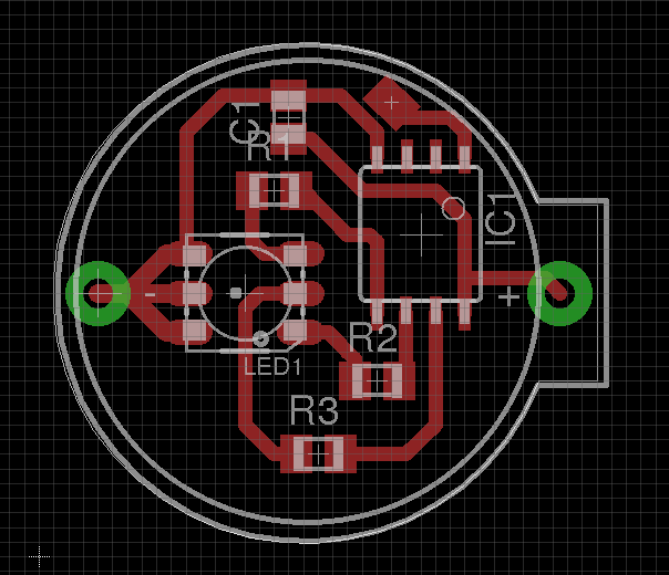
#include <avr/io.h> #include <avr/eeprom.h> #include <util/delay.h> #include <avr/interrupt.h> #define r_pwm(pwm) OCR0A = pwm #define b_pwm(pwm) OCR0B = pwm #define g_pwm(pwm) OCR1A = pwm #define NUM_MODES 16 int main(void) { /* Init LED GPIO pins */ DDRB = 7; /* pins 0, 1, 2 */ /* Init PWM timers */ /* Timer0 is for R and G channels */ TCCR0A = (1<<COM0A1)|(1<<COM0B1)|(WGM01)|(WGM00); TCCR0B = (1<<CS00); /* divide by 1 */ /* Timer 1 is for B channel; enable interrupts */ TIMSK = (1<<OCIE1A)|(1<<TOIE1); TCCR1 = (1<<CS10); /* divide by 1 */ sei(); /* Get mode value from the EEPROM and update it */ uint8_t mode = eeprom_read_byte((uint8_t *) 1); mode++; if (mode >= NUM_MODES) mode = 0; eeprom_write_byte((uint8_t *) 1, mode); uint8_t i; while(1) { switch(mode >> 1) { case 0: r_pwm(255); break; case 1: g_pwm(255); break; case 2: b_pwm(255); break; case 3: r_pwm(255); g_pwm(255); break; case 4: g_pwm(255); b_pwm(255); break; case 5: r_pwm(255); b_pwm(255); break; case 6: r_pwm(255); g_pwm(255); b_pwm(255); break; case 7: for (i=0; i < 255; i++) { r_pwm(255-i); g_pwm(i); _delay_ms(20); } for (i=0; i < 255; i++) { g_pwm(255-i); b_pwm(i); _delay_ms(20); } for (i=0; i < 255; i++) { b_pwm(255-i); r_pwm(i); _delay_ms(20); } } } return 0; } ISR(TIM1_OVF_vect) { if (OCR1A != 0) PORTB |= (1<<2); } ISR(TIM1_COMPA_vect) { PORTB &= ~(1<<2); } Circuit diagram and PCB layout (from Eagle CAD)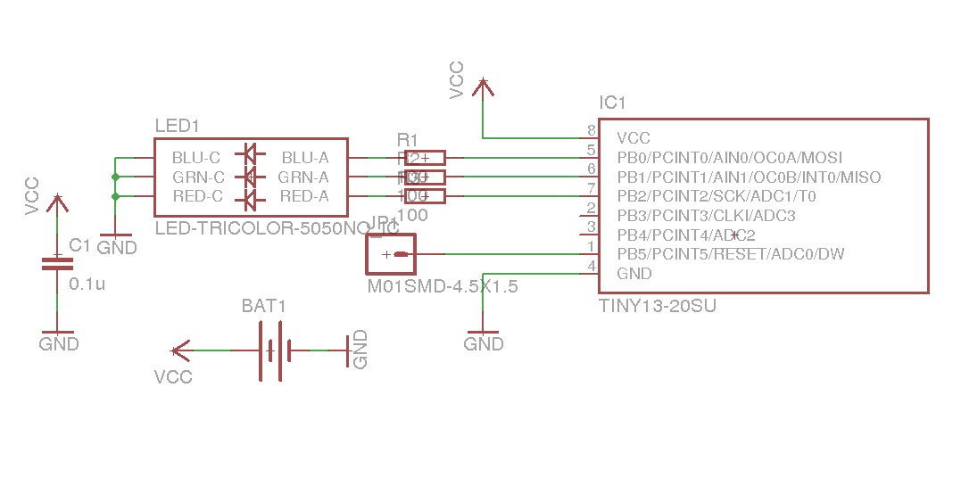
Fuse bits can be counted here , I felt that 1 MHz is enough for me for comfortable PWM and for low power consumption. Generally speaking, fusion beats turned out to be standard for tiny45, so you can not change them.
I was already eager to try out a new craft in practice, because, having hurriedly sprinkled varnish from a can and letting it lie under the lamp for 5 minutes, I took it and ran out into the street with a camera (it was already quite late in the evening, just suitable conditions for testing).
And here is the result (the video does not differ from the one inserted above to attract attention):
Snowballs did not want to be molded at all, and yet I warmed up a handful of snow in my hands and everything turned out well!
Important
For the idea of many thanks to Comrade. Kidar .
I posted all the materials on this project in Dropbox . When the time comes, I will prepare a separate makefile, and now after unpacking: make antares && make build, after which you can upload the images / antares.hex file to the chip in a convenient way.
Thanks for attention!
UPD: Updated archives with source files; Now, a complete PDF file for self-printing is included with the printed circuit board, and in the archive with the program is a hex file with ready-made firmware.
Source: https://habr.com/ru/post/207602/
All Articles