Do-it-yourself balancing stand on the SiLabs C8051F120-TB debug board
If you want to balance something rotating, be it a wheel, a propeller or a flying saucer. Or you are interested in the story of how a programmer’s working days are going. A fascinating story of creating a balancing stand ...
Preface.
I express my gratitude to my head, Dmitriev, Ivan Alekseevich, engineer, designer Arapov, Andrey, and electronics engineers, Turaev, Alexander, and Gidal Grigorievich. This stand is the result of the work of the team.
I'll start with the pre story: I work as a programmer in the organization
Not at all secret, but not relevant, I can only say that we are engaged in UAVwhere many different interesting tasks periodically appear, and we have a need to balance the high precision of the propeller of the aircraft. Equipment for such a balancing as it turned out you can buy, but it will be very expensive, they decided to do it themselves.
')
I will tell you a little why it was needed. Our aircraft, with this propeller, badly sausage at idle (800 rev / min). Usually balance such things, statically and dynamically. Static balancing consists in balancing relative to the center of rotation, without rotation, and dynamic balancing is during rotation.
As for static balancing, then everything is clearly screw just balanced around the center of rotation, but what to do with dynamic balancing, when the screw starts to create a vibration during rotation.
For such a task was built
simple device
which can measure the acceleration of the frame with the body of rotation, and give a signal about the passage through 0 degrees of the shaft, which rotates the balanced screw.consisting of a frame attached on springs to a massive base.
An electric motor is mounted on a massive base, and through a pulley it rotates an axis on which a balanced screw is mounted. Accelerometers are also installed on the frame, and a hall sensor on the axis with a screw. The electric motor is connected to the frequency changer, which controls the frequency of its rotation.
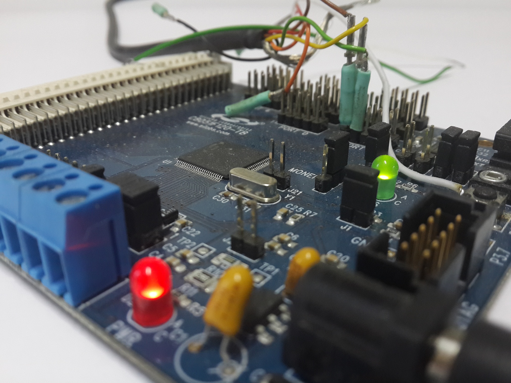
An accelerometer on two axes was used as a deflection meter, through an amplifier connected to the ADC of the SiLabs C8051F120-TB debug board. In order to catch the moment of the rotation of the rotating body through 0 degrees, a hall sensor was set, the signal from which was fed to another leg of the debug board.
So we got a simple unit
An electric motor is mounted on a massive base, and through a pulley it rotates an axis on which a balanced screw is mounted. Accelerometers are also installed on the frame, and a hall sensor on the axis with a screw. The electric motor is connected to the frequency changer, which controls the frequency of its rotation.
An accelerometer on two axes was used as a deflection meter, through an amplifier connected to the ADC of the SiLabs C8051F120-TB debug board. In order to catch the moment of the rotation of the rotating body through 0 degrees, a hall sensor was set, the signal from which was fed to another leg of the debug board.
So we got a simple unit
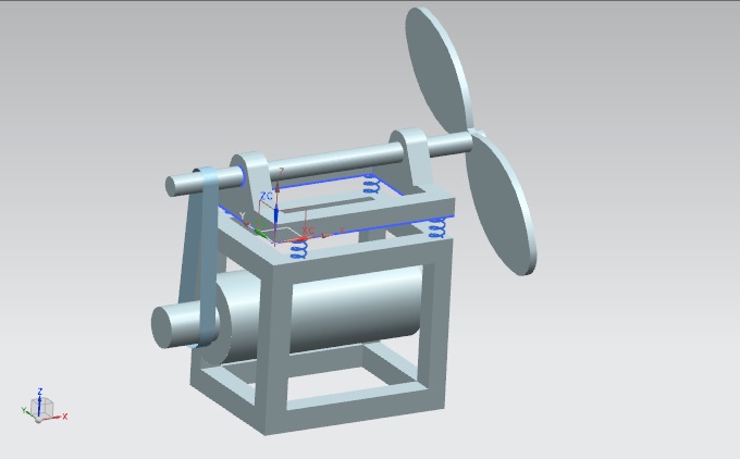
/ appearance of a simple device /
I was given this construction, and they set the task programmatically to find out what quantity of
And I started an exciting job.

At first, I thought that I would manage in one day, and the task is very simple. But when taking a signal with an oscilloscope, it was found that the vibration of the entire installation, interference from the mains, and other noise, turn the captured signal from the ADC into a uniform incomprehensible noise. Although if you take a closer look, then there is a clear periodic maximum and minimum. It took about a week to debug the software and hardware, or even a little more, but then the accuracy of the device began to please the eye.
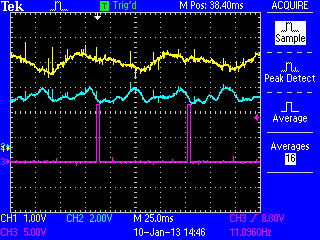
/ Oscilloscope testimony /
I wrote a program on the debug board that takes readings and sends them to the COM port.
defines
We configure the controller, we define the main variables, we select arrays and constants. We are preparing a debug board for programming.
#include "c8051f120.h" #define SYSCLK 98000000 // #define BAUDRATEU0 57600 // Uart0 RS232 COM #define SAMPLE_RATE 24500000 // Sample frequency in Hz #define INT_DEC 256 #define SAR_CLK 12250000 // #define FREQT0 (748*2) // 0 #define BUFADCSIZE 512 //BUFADC sfr16 ADC0 = 0xbe; // ADC0 data sfr16 RCAP2 = 0xca; // Timer2 capture/reload sfr16 RCAP3 = 0xca; // Timer3 capture/reload sfr16 TMR2 = 0xcc; // Timer2 sfr16 TMR3 = 0xcc; // Timer3 bit ProcessFlag = 0, ADCFlag = 0, flFree = 1, flNewADC = 0; // xdata unsigned int BufADC[BUFADCSIZE], ADCcount = 0, RTC = 0, RTCP = 0, int_dec = INT_DEC, tmpA = 0, lastTmp = 0; xdata float Propeller = 0.0, tmp_float; xdata long accumulator = 0L; #define RESETTICK (1496) sbit LED = P1^6; // sbit BUTTON = P3^7; // //UART0 #define NBFM 50 xdata unsigned char BuferFromModem [NBFM]; xdata unsigned char wBFM, rBFM, marBFM; #define SIZE_BUFFER0 50 xdata char BufferInModem[SIZE_BUFFER0]; xdata int r0, rk; bit flTransmiter; //----- void OutModem1(unsigned char Data, char i) { BufferInModem[i] = Data | 0x80; } //------------------------------------------------------------------------------ void OutModem2(unsigned int Data, char i) { BufferInModem[i] = (Data & 0x007f)| 0x80; BufferInModem[i+1] = ((Data & 0x3f80) >> 7)| 0x80; } //------------------------------------------------------------------------------ void OutModem4(unsigned long int Data, char i) { BufferInModem[i] = (Data & 0x0000007f)| 0x80; BufferInModem[i+1] = ((Data & 0x3f80) >> 7) | 0x80; BufferInModem[i+2] = ((Data & 0x1fc000) >> 14) | 0x80; BufferInModem[i+3] = ((Data & 0xfe00000)>> 21) | 0x80; } //---- void OSCILLATOR_Init (void) { int loop; char SFRPAGE_SAVE = SFRPAGE; SFRPAGE = CONFIG_PAGE; OSCICN = 0x83; CLKSEL = 0x00; SFRPAGE = CONFIG_PAGE; PLL0CN = 0x00; SFRPAGE = LEGACY_PAGE; FLSCL = 0x10; SFRPAGE = CONFIG_PAGE; PLL0CN |= 0x01; PLL0DIV = 0x01; PLL0FLT = 0x01; PLL0MUL = 0x04; for (loop=0; loop<256; loop++); PLL0CN |= 0x02; while(!(PLL0CN & 0x10)); CLKSEL = 0x02; SFRPAGE = SFRPAGE_SAVE; } /*Init*/ void Init() { // SFRPAGE = TIMER01_PAGE; TCON = 0x51; TMOD = 0x11; CKCON = 0x18; SFRPAGE = TMR3_PAGE; TMR3CN = 0x04; TMR3CF = 0x08; RCAP3 = -SYSCLK/SAMPLE_RATE; TMR3 = RCAP3; EIE2 &= ~0x01; TR3 = 1; // Uart SFRPAGE = TMR2_PAGE; TMR2CF = 0x08; // Timer 2 Configuration RCAP2 = - ((long) SYSCLK/BAUDRATEU0/16); TMR2L = 0x00; // Timer 2 Low Byte TMR2H = 0x00; // Timer 2 High Byte TMR2CN = 0x04; // Timer 2 CONTROL TR2 = 1; SFRPAGE = UART0_PAGE; SCON0 = 0x50; SSTA0 = 0x05; ES0 = 1; // ADC() SFRPAGE = ADC0_PAGE; AMX0SL = 0x01; ADC0CN = 0x80; SFRPAGE = ADC0_PAGE; ADC0CN = 0x04; REF0CN = 0x07; AMX0CF = 0x00; AMX0SL = 0x01; ADC0CF = (SYSCLK/SAR_CLK) << 3; ADC0CF |= 0x00; // PGA gain => 00 = 1 (default), 01 =2, 02 = 4, 03 = 8 EIE2 |= 0x02; // enable ADC interrupts SFRPAGE = ADC0_PAGE; ADC0CN = 0x84; // SFRPAGE = CONFIG_PAGE; P0MDOUT = 0xFF; P1MDOUT = 0xFF; P2MDOUT = 0xFF; P3MDOUT = 0xFF;*/ XBR0 = 0x44; XBR1 = 0x04; XBR2 = 0x40; // OSCILLATOR_Init(); // IE = 0x9B; EIE2 |= 0x02; // IP = 0x13; EIP2 = 0x02; // } Main function
Here we are constantly spinning in an infinite loop, and send the received measurements of the ADC
//------------------------------------------------------------------- void main(void) { xdata unsigned int i=0, tmpint; WDTCN = 0xde; // , WDTCN = 0xad; // , , EA=0; // Init(); // i = 0; while(i++ < BUFADCSIZE) { BufADC[i]=0; } EA=1; while(1) { if(RTC>(7*FREQT0)) { IE0=1; } if(ProcessFlag == 1) { ADCFlag = 0; flFree = 0; EIE2 &= ~0x02; // // tmpint = ADCcount; ADCcount = 1; while(ADCcount < tmpint) { //Write to UART0-------------------------------------- BufferInModem[0] = 40 | 0x40; BufferInModem[0] &= ~0x80; OutModem2((int)Propeller, 1); OutModem2((int)ADCcount, 3); OutModem2((int)BufADC[ADCcount++],5); OutModem2((int)tmpint, 7); r0 = 0; rk = 9; BufferInModem[rk] = 0; for (i = r0; i < rk; i++ ) BufferInModem[rk] = BufferInModem[rk] ^ BufferInModem[i]; BufferInModem[rk] = BufferInModem[rk] | 0x80; rk++; flTransmiter = 1; SFRPAGE = 0x00; TI0 = 1; RTC=0; while(flTransmiter) { if(RTC>(RESETTICK)) { RTC=0; break; } } RTC=0; LED=0; } i = 0; while(i++ < BUFADCSIZE) { BufADC[i]=0; } ADCcount = 0; ProcessFlag = 0; flFree = 1; } } } Create an interrupt event from the leg to which the hall sensor is connected.
Interruptions
Here we monitor interrupts from the Hall sensor.
void INT0 (void) interrupt 0 // { if(LED!=1) { LED=1; // } else if(RTC > RTCP) // ( 0 - 60000 /) { Propeller = Propeller+((60.0*FREQT0/(RTC - RTCP))-Propeller)*1.0; RTCP = RTC; } RTCP=0; RTC=0; if((flFree == 1)&& (ADCFlag == 1)) { ProcessFlag = 1; } else if(!ProcessFlag) EIE2 |= 0x02; // return; } To know exactly how much time has passed, we start the timer, and count the time in it
Timer
void TIMER_ISR0 (void) interrupt 1 // FREQT0 = SYSCLK/65535 { RTC++; return; } A separate event, this is an operation with an input / output port.
void UART0_isr(void) interrupt 4 // , { xdata char SFRPAGE_SAVE = SFRPAGE; SFRPAGE = UART0_PAGE; if (RI0) { BuferFromModem [wBFM++] = SBUF0; // if(wBFM >= NBFM) { wBFM = 0; marBFM = 1; } RI0 = 0; } if (TI0) { if(r0 < rk) { SBUF0 = BufferInModem[r0++]; // } else { flTransmiter = 0; } TI0 = 0; } SFRPAGE = SFRPAGE_SAVE; return; } All data removed from the ADC is written to the buffer in order to transfer the whole pack in one turn. This method allowed not to spend time on the transfer during the removal of information, as a result, works faster and removes more points.
ADC interrupts
Here we write to the buffer the measurement of the ADC
void ADC0_ISR (void) interrupt 15 // { xdata char SFRPAGE_SAVE = SFRPAGE; SFRPAGE = ADC0_PAGE; // , AD0INT = 0; accumulator += ADC0; int_dec--; if (int_dec == 0) { int_dec = INT_DEC; BufADC[ADCcount] = accumulator >> 8; AMX0SL = 0x00; ADCcount++; ADCFlag = 1; if(ADCcount>BUFADCSIZE) { ADCcount=BUFADCSIZE; ProcessFlag=1; EIE2 &= ~0x02; // } accumulator = 0L; } SFRPAGE = SFRPAGE_SAVE; return; } In order to somehow separate the necessary deviations, on the desktop application, I decided to apply the Fourier transform, which I had previously used to process the images, after tweaking a bit with the tambourine, it turned out to select the necessary frequencies.
I used C ++ Builder 6.0 to develop the interface
Header plug-in libraries, variables, constants
//--------------------------------------------------------------------------- #include <vcl.h> #pragma hdrstop #include "balansCom4.h" #include <windows.h> #include <vector.h> #include "fstream.h" #include "math.h" //--------------------------------------------------------------------------- #define assert(ignore)((void)0) #define BUFSIZE 4096 //--------------------------------------------------------------------------- #pragma package(smart_init) #pragma link "CPort" #pragma link "PERFGRAP" #pragma resource "*.dfm" TForm1 *Form1; int N=1024,k=10; ShortComplex arr[4096]; double Amp_F[4096]; double Phase_F[4096]; double Amp_max=0, Phase_max=0; float r=0,rmax=0, fi=0, xx=0, yy=0; float K_flt = 0.00005; float Krmax = 0.05; float kAmp = 0.1; float a=1, b=0; //--------------------------------------------------------------------------- bool perekl=false; struct hComException{}; String tmptxt; float RadMass[365], RadMassMax, j_max; int fiMax, WACHDOG; long data_i=0; long bad = 0; int V, Xlast, A, Alast, Vlast; #define COM "Com5" #define BodRate CBR_57600 #define TIMEOUT 3000 //--------------------------------------------------------------------------- For the selection of the desired frequency from the received signal, the direct and inverse Fourier transform turned out to be very useful. The data flows in a continuous stream, and in order to process them, I applied an optimized version, the so-called FFT . This is not a panacea, and it is better to parallelize and use the GPU for video stream processing, but for this task it is quite applicable.
FFT function
static unsigned char reverse256[]= { 0x00, 0x80, 0x40, 0xC0, 0x20, 0xA0, 0x60, 0xE0, 0x10, 0x90, 0x50, 0xD0, 0x30, 0xB0, 0x70, 0xF0, 0x08, 0x88, 0x48, 0xC8, 0x28, 0xA8, 0x68, 0xE8, 0x18, 0x98, 0x58, 0xD8, 0x38, 0xB8, 0x78, 0xF8, 0x04, 0x84, 0x44, 0xC4, 0x24, 0xA4, 0x64, 0xE4, 0x14, 0x94, 0x54, 0xD4, 0x34, 0xB4, 0x74, 0xF4, 0x0C, 0x8C, 0x4C, 0xCC, 0x2C, 0xAC, 0x6C, 0xEC, 0x1C, 0x9C, 0x5C, 0xDC, 0x3C, 0xBC, 0x7C, 0xFC, 0x02, 0x82, 0x42, 0xC2, 0x22, 0xA2, 0x62, 0xE2, 0x12, 0x92, 0x52, 0xD2, 0x32, 0xB2, 0x72, 0xF2, 0x0A, 0x8A, 0x4A, 0xCA, 0x2A, 0xAA, 0x6A, 0xEA, 0x1A, 0x9A, 0x5A, 0xDA, 0x3A, 0xBA, 0x7A, 0xFA, 0x06, 0x86, 0x46, 0xC6, 0x26, 0xA6, 0x66, 0xE6, 0x16, 0x96, 0x56, 0xD6, 0x36, 0xB6, 0x76, 0xF6, 0x0E, 0x8E, 0x4E, 0xCE, 0x2E, 0xAE, 0x6E, 0xEE, 0x1E, 0x9E, 0x5E, 0xDE, 0x3E, 0xBE, 0x7E, 0xFE, 0x01, 0x81, 0x41, 0xC1, 0x21, 0xA1, 0x61, 0xE1, 0x11, 0x91, 0x51, 0xD1, 0x31, 0xB1, 0x71, 0xF1, 0x09, 0x89, 0x49, 0xC9, 0x29, 0xA9, 0x69, 0xE9, 0x19, 0x99, 0x59, 0xD9, 0x39, 0xB9, 0x79, 0xF9, 0x05, 0x85, 0x45, 0xC5, 0x25, 0xA5, 0x65, 0xE5, 0x15, 0x95, 0x55, 0xD5, 0x35, 0xB5, 0x75, 0xF5, 0x0D, 0x8D, 0x4D, 0xCD, 0x2D, 0xAD, 0x6D, 0xED, 0x1D, 0x9D, 0x5D, 0xDD, 0x3D, 0xBD, 0x7D, 0xFD, 0x03, 0x83, 0x43, 0xC3, 0x23, 0xA3, 0x63, 0xE3, 0x13, 0x93, 0x53, 0xD3, 0x33, 0xB3, 0x73, 0xF3, 0x0B, 0x8B, 0x4B, 0xCB, 0x2B, 0xAB, 0x6B, 0xEB, 0x1B, 0x9B, 0x5B, 0xDB, 0x3B, 0xBB, 0x7B, 0xFB, 0x07, 0x87, 0x47, 0xC7, 0x27, 0xA7, 0x67, 0xE7, 0x17, 0x97, 0x57, 0xD7, 0x37, 0xB7, 0x77, 0xF7, 0x0F, 0x8F, 0x4F, 0xCF, 0x2F, 0xAF, 0x6F, 0xEF, 0x1F, 0x9F, 0x5F, 0xDF, 0x3F, 0xBF, 0x7F, 0xFF, }; static long double temp; inline void operator+=(ShortComplex &x, const Complex &y) { x.re += (double)y.re; x.im += (double)y.im; } inline void operator-=(ShortComplex &x, const Complex &y) { x.re -= (double)y.re; x.im -= (double)y.im; } inline void operator*=(Complex &x, const Complex &y) { temp = x.re; x.re = temp * y.re - x.im * y.im; x.im = temp * y.im + x.im * y.re; } inline void operator*=(Complex &x, const ShortComplex &y) { temp = x.re; x.re = temp * y.re - x.im * y.im; x.im = temp * y.im + x.im * y.re; } inline void operator/=(ShortComplex &x, double div) { x.re /= div; x.im /= div; } //array exp(-2*pi*j/2^n) for n= 1,...,32 //exp(-2*pi*j/2^n) = Complex( cos(2*pi/2^n), -sin(2*pi/2^n) ) static Complex W2n[32]={ {-1.00000000000000000000000000000000, 0.00000000000000000000000000000000}, // W2 calculator (copy/paste) : po, ps { 0.00000000000000000000000000000000, -1.00000000000000000000000000000000}, // W4: p/2=o, p/2=s { 0.70710678118654752440084436210485, -0.70710678118654752440084436210485}, // W8: p/4=o, p/4=s { 0.92387953251128675612818318939679, -0.38268343236508977172845998403040}, // p/8=o, p/8=s { 0.98078528040323044912618223613424, -0.19509032201612826784828486847702}, // p/16= { 0.99518472667219688624483695310948, -9.80171403295606019941955638886e-2}, // p/32= { 0.99879545620517239271477160475910, -4.90676743274180142549549769426e-2}, // p/64= { 0.99969881869620422011576564966617, -2.45412285229122880317345294592e-2}, // p/128= { 0.99992470183914454092164649119638, -1.22715382857199260794082619510e-2}, // p/256= { 0.99998117528260114265699043772857, -6.13588464915447535964023459037e-3}, // p/(2y9)= { 0.99999529380957617151158012570012, -3.06795676296597627014536549091e-3}, // p/(2y10)= { 0.99999882345170190992902571017153, -1.53398018628476561230369715026e-3}, // p/(2y11)= { 0.99999970586288221916022821773877, -7.66990318742704526938568357948e-4}, // p/(2y12)= { 0.99999992646571785114473148070739, -3.83495187571395589072461681181e-4}, // p/(2y13)= { 0.99999998161642929380834691540291, -1.91747597310703307439909561989e-4}, // p/(2y14)= { 0.99999999540410731289097193313961, -9.58737990959773458705172109764e-5}, // p/(2y15)= { 0.99999999885102682756267330779455, -4.79368996030668845490039904946e-5}, // p/(2y16)= { 0.99999999971275670684941397221864, -2.39684498084182187291865771650e-5}, // p/(2y17)= { 0.99999999992818917670977509588385, -1.19842249050697064215215615969e-5}, // p/(2y18)= { 0.99999999998204729417728262414778, -5.99211245264242784287971180889e-6}, // p/(2y19)= { 0.99999999999551182354431058417300, -2.99605622633466075045481280835e-6}, // p/(2y20)= { 0.99999999999887795588607701655175, -1.49802811316901122885427884615e-6}, // p/(2y21)= { 0.99999999999971948897151921479472, -7.49014056584715721130498566730e-7}, // p/(2y22)= { 0.99999999999992987224287980123973, -3.74507028292384123903169179084e-7}, // p/(2y23)= { 0.99999999999998246806071995015625, -1.87253514146195344868824576593e-7}, // p/(2y24)= { 0.99999999999999561701517998752946, -9.36267570730980827990672866808e-8}, // p/(2y25)= { 0.99999999999999890425379499688176, -4.68133785365490926951155181385e-8}, // p/(2y26)= { 0.99999999999999972606344874922040, -2.34066892682745527595054934190e-8}, // p/(2y27)= { 0.99999999999999993151586218730510, -1.17033446341372771812462135032e-8}, // p/(2y28)= { 0.99999999999999998287896554682627, -5.85167231706863869080979010083e-9}, // p/(2y29)= { 0.99999999999999999571974138670657, -2.92583615853431935792823046906e-9}, // p/(2y30)= { 0.99999999999999999892993534667664, -1.46291807926715968052953216186e-9}, // p/(2y31)= }; void fft(ShortComplex *x, int T, bool complement) { unsigned int I, J, Nmax, N, Nd2, k, m, mpNd2, Skew; unsigned char *Ic = (unsigned char*) &I; unsigned char *Jc = (unsigned char*) &J; ShortComplex S; ShortComplex *Wstore, *Warray; Complex WN, W, Temp, *pWN; Nmax = 1 << T; //first interchanging for(I = 1; I < Nmax - 1; I++) { Jc[0] = reverse256[Ic[3]]; Jc[1] = reverse256[Ic[2]]; Jc[2] = reverse256[Ic[1]]; Jc[3] = reverse256[Ic[0]]; J >>= (32 - T); if (I < J) { S = x[I]; x[I] = x[J]; x[J] = S; } } //rotation multiplier array allocation Wstore = new ShortComplex[Nmax / 2]; Wstore[0].re = 1.0; Wstore[0].im = 0.0; //main loop for(N = 2, Nd2 = 1, pWN = W2n, Skew = Nmax >> 1; N <= Nmax; Nd2 = N, N += N, pWN++, Skew >>= 1) { //WN = W(1, N) = exp(-2*pi*j/N) WN= *pWN; if (complement) WN.im = -WN.im; for(Warray = Wstore, k = 0; k < Nd2; k++, Warray += Skew) { if (k & 1) { W *= WN; *Warray = W; } else W = *Warray; for(m = k; m < Nmax; m += N) { mpNd2 = m + Nd2; Temp = W; Temp *= x[mpNd2]; x[mpNd2] = x[m]; x[mpNd2] -= Temp; x[m] += Temp; } } } delete [] Wstore; if (complement) { for( I = 0; I < Nmax; I++ ) x[I] /= Nmax; } } Prepare a GUI , and configure the COM port for reception.
Options at startup and shutdown
__fastcall TForm1::TForm1(TComponent* Owner) : TForm(Owner) { for(int i=0; i<362; i++) RadMass[i]=0; RadMassMax=0; Image1->Canvas->Rectangle(0,0,Image1->Width, Image1->Height); int i=0; float r, fi=0; float xx, yy; while(i<100) { Image1->Canvas->Pen->Color=clGreen; i=i+10; r=i; fi=0; while(fi<360) { fi=fi+1; xx = r*cos(fi) + Image1->Width/2; yy = r*sin(fi) + Image1->Height/2; Image1->Canvas->Ellipse((int)xx,(int)yy, (int)xx+2,(int)yy+2); } } Image1->Canvas->Pen->Color=clBlack; Button2Click(Owner); flEdit=0; hCom = CreateFile(COM,GENERIC_READ | GENERIC_WRITE,0,NULL, OPEN_EXISTING, FILE_FLAG_OVERLAPPED, NULL); if( hCom == INVALID_HANDLE_VALUE ) { ShowMessage("Com port error"); CloseHandle(hCom); Stat->SimpleText="Com port error"; } else { SetCommMask(hCom, EV_RXCHAR); SetupComm(hCom, 1500, 1500); CommTimeOuts.ReadIntervalTimeout = MAXDWORD; CommTimeOuts.ReadTotalTimeoutMultiplier = TIMEOUT; CommTimeOuts.ReadTotalTimeoutConstant = TIMEOUT; CommTimeOuts.WriteTotalTimeoutMultiplier = TIMEOUT; CommTimeOuts.WriteTotalTimeoutConstant = TIMEOUT; if(!SetCommTimeouts(hCom, &CommTimeOuts)) { hCom = 0; throw hComException(); } memset(&dcb, 0, sizeof(dcb)); dcb.DCBlength = sizeof(DCB); GetCommState(hCom, &dcb); dcb.BaudRate = BodRate; dcb.fParity = 0; dcb.ByteSize = 8; dcb.Parity = NOPARITY; dcb.StopBits = ONESTOPBIT; dcb.fAbortOnError = FALSE; dcb.fDtrControl = DTR_CONTROL_DISABLE; dcb.fRtsControl = RTS_CONTROL_DISABLE; dcb.fBinary = TRUE; dcb.fParity = FALSE; dcb.fInX = FALSE; dcb.fOutX = FALSE; dcb.XonChar = 0; dcb.XoffChar = (unsigned char)0xFF; dcb.fErrorChar = FALSE; dcb.fNull = FALSE; dcb.fOutxCtsFlow = FALSE; dcb.fOutxDsrFlow = FALSE; dcb.XonLim = 128; dcb.XoffLim = 128; SetCommState(hCom,&dcb); PurgeComm(hCom, PURGE_RXCLEAR); begin = GetTickCount(); tmptxt = COM; tmptxt += " br"; tmptxt += dcb.BaudRate; tmptxt += " p"; tmptxt += dcb.Parity; tmptxt += " By"; tmptxt += dcb.ByteSize; tmptxt += " sb"; tmptxt += dcb.StopBits; Stat->SimpleText= tmptxt; overlapped.hEvent = CreateEvent(NULL, true, true, NULL); } } void __fastcall TForm1::FormClose(TObject *Sender, TCloseAction &Action) { CloseHandle(hCom); } I decided to attach the functions of saving and loading, so that you can somehow raise the data if necessary, although it is not necessary for the stand. Although the data was saved, they were never used in the future, so you can not do it.
Save and Load Functions
void TForm1::SaveToFile(String FileName) { fstream file_; file_.open(FileName.c_str(), ios::out); if (!file_) { file_.close(); return; } int count_ = 0, tmp_count; tmp_count = Series1->XValues->MaxValue-1; if(tmp_count>(Series2->XValues->MaxValue-1)) tmp_count = Series2->XValues->MaxValue-1; if(tmp_count>(Series6->XValues->MaxValue-1)) tmp_count = Series6->XValues->MaxValue-1; while(count_++ < tmp_count) { int a1Propeller = Series1->YValue[count_]; int a2X1 = Series2->YValue[count_]; int a6Ugol = Series6->YValue[count_]; file_ << a1Propeller << " " << a2X1 << " " << a6Ugol << " " ; } file_.close(); } void TForm1::LoadFromFile(String FileName) { fstream file; file.open(FileName.c_str()); if (!file) { file.close(); return; } float a1Propeller = 0, a2X1 = 0, a6Ugol = 0; Series1->Clear(); Series2->Clear(); Series6->Clear(); long file_i=0; file_i=0; while(!file.eof()) { file >> a1Propeller >> a2X1 >> a6Ugol; Application->ProcessMessages(); Series1->Add(a1Propeller); Series2->Add(a2X1); Series6->Add(a6Ugol); Dannye->Cells[0][0]="Propeller"; Dannye->Cells[1][0]=a1Propeller; Dannye->Cells[0][1]="X1"; Dannye->Cells[1][1]=a2X1; float r, fi, xx, yy; r = (Image1->Height/2)*(a*a2X1-b)/4095; fi = a6Ugol; RadMass[(int)fi]=RadMass[(int)fi] + (r-RadMass[(int)fi])*Krmax; if(RadMass[(int)fi]>RadMassMax) { float lastRadMax; int lastfiMax; lastfiMax = fiMax; lastRadMax = RadMass[lastfiMax]; Image1->Canvas->Pen->Color=clWhite; Image1->Canvas->MoveTo(Image1->Width/2, Image1->Height/2); xx= lastRadMax*cos(lastfiMax) + Image1->Width/2; yy= lastRadMax*sin(lastfiMax) + Image1->Height/2; Image1->Canvas->LineTo(xx, yy); Image1->Canvas->MoveTo(xx, yy+1); Image1->Canvas->LineTo(Image1->Width/2, Image1->Height/2+1); Image1->Canvas->MoveTo(xx, yy-1); Image1->Canvas->LineTo(Image1->Width/2, Image1->Height/2-1); Image1->Canvas->MoveTo(xx+1, yy); Image1->Canvas->LineTo(Image1->Width/2+1, Image1->Height/2); Image1->Canvas->MoveTo(xx-1, yy); Image1->Canvas->LineTo(Image1->Width/2-1, Image1->Height/2); RadMassMax = RadMass[(int)fi]; fiMax = fi; lastRadMax = RadMassMax; lastfiMax = fiMax; Image1->Canvas->Pen->Color=clRed; Image1->Canvas->MoveTo(Image1->Width/2, Image1->Height/2); xx= RadMassMax*cos(2*M_PI*fiMax/360)+Image1->Width/2; yy= RadMassMax*sin(2*M_PI*fiMax/360) + Image1->Height/2; Image1->Canvas->LineTo(xx, yy); Image1->Canvas->MoveTo(xx, yy+1); Image1->Canvas->LineTo(Image1->Width/2, Image1->Height/2+1); Image1->Canvas->MoveTo(xx, yy-1); Image1->Canvas->LineTo(Image1->Width/2, Image1->Height/2-1); Image1->Canvas->MoveTo(xx+1, yy); Image1->Canvas->LineTo(Image1->Width/2+1, Image1->Height/2); Image1->Canvas->MoveTo(xx-1, yy); Image1->Canvas->LineTo(Image1->Width/2-1, Image1->Height/2); Image1->Canvas->Pen->Color=clBlack; Dannye->Cells[0][3]=""; Dannye->Cells[1][3]= (int)RadMassMax; } xx = r*cos(2*M_PI*fi/360) + Image1->Width/2; yy = r*sin(2*M_PI*fi/360) + Image1->Height/2; Image1->Canvas->Ellipse((int)xx,(int)yy, (int)xx+2,(int)yy+2); if (file_i > (N+1)) { int count_= 0; while(count_ < N) { arr[count_].re= Series2->YValue[count_+file_i-N]; arr[count_++].im= 0.0; } Series7->Clear(); Series8->Clear(); fft(arr, k, false); int i=0; double nSamplesPerSec; int Nmax= (N + 1) / 2; double *freq= new double[Nmax]; double *amp= new double[Nmax]; double *phase= new double[Nmax]; int j= 0; double limit= 0.001; double abs2min= limit * limit * N * N; double abs2max= 10E150; if (arr[i].re >= limit) { amp[j]= arr[i].re / N; freq[j]= 0.0; phase[j]= 0.0; ++j; } ++i; for(i= 1; i < Nmax; ++i) { double re= arr[i].re; double im= arr[i].im; long double abs2; abs2 = re * re + im * im; if (abs2 < abs2min) continue; if (abs2 > abs2max) abs2=abs2max; amp[j]= 2.0 * sqrt((double)abs2) / N; Amp_F[j] = Amp_F[j]+(amp[j]-Amp_F[j])*K_flt; Series7->Add(Amp_F[j]); phase[j]= atan2(im, re); phase[j]+= M_PI_2; if (phase[j] > M_PI) phase[j]-= 2*M_PI; phase[j]= phase[j] * M_PI / 180.0; Phase_F[j] = Phase_F[j] + (phase[j] - Phase_F[j])*K_flt; Series8->Add(Phase_F[j]); freq[j]= (nSamplesPerSec * i) / N; ++j; } delete[] amp; delete[] freq; delete[] phase; } file_i++; } file.close(); return; } //--------------------------------------------------------------------------- void __fastcall TForm1::Button1Click(TObject *Sender) { String FileName_; FileName_ = ExtractFilePath(Application->ExeName); FileName_ += "Data\\"; FileName_ += FormatDateTime("dd_mmm_yyy'-'hh_nn'",Now()); SaveDialog1->FileName = FileName_; if(SaveDialog1->Execute()) { SaveToFile(SaveDialog1->FileName); flEdit=0; } } //--------------------------------------------------------------------------- void __fastcall TForm1::Button3Click(TObject *Sender) { if(OpenDialog1->Execute()) { LoadFromFile(OpenDialog1->FileName); } } To receive and decrypt the buffer automatically, I made it possible to do this on a timer, not quite a good idea, now I would do it differently, I would collect data on the arrival in a separate stream, and transmit to the output, so as not to interfere with the input interface and others applications. However, this option was viable, and coped with its task quite successfully.
Timer with processing
void __fastcall TForm1::Timer1Timer(TObject *Sender) { if(CheckBox1->Checked) { flEdit=1; int Propeller, X1, ADCcount, ADCcountMax, Amax; unsigned char tmp40; int attempts = 3, nLetter40 = 11; int rBUF=0, wBUF=0, marBUF=0; feedback = 0; BYTE data1[BUFSIZE]; vector<unsigned char> data(data1, data1+BUFSIZE); unsigned char* buf = &data[0]; ADCcountMax=0; WaitCommEvent(hCom, &mask, &overlapped); signal = WaitForSingleObject(overlapped.hEvent, 7000); if(signal == WAIT_OBJECT_0) { if(GetOverlappedResult(hCom, &overlapped, &feedback, true)) if((mask & EV_RXCHAR)!=0) { ClearCommError(hCom, &feedback, &comstat); btr = comstat.cbInQue; if(btr) { ReadFile(hCom, buf, btr, &feedback, &overlapped); wBUF+=btr;//(DWORD)data.size(); if(wBUF >= BUFSIZE) { wBUF = 0; marBUF = 1; } } while(rBUF < (wBUF + (marBUF*BUFSIZE))) { unsigned char tmpBuf = data[rBUF]; tmpBuf = tmpBuf&~0x80; if(tmpBuf==(0x40 | 40)) { nLetter40=0; tmp40 = 0; tmp40 = tmp40 ^ data[rBUF]; } else if(nLetter40==0 && (data[rBUF]>>7)==1) { nLetter40++; Propeller = data[rBUF]&~0x80; tmp40 = tmp40 ^ data[rBUF]; } else if(nLetter40==1 && (data[rBUF]>>7)==1) { nLetter40++; Propeller |= ((int)(data[rBUF]&~0x80)<<7); tmp40 = tmp40 ^ data[rBUF]; } else if(nLetter40==2 && (data[rBUF]>>7)==1) { nLetter40++; ADCcount = data[rBUF]&~0x80; tmp40 = tmp40 ^ data[rBUF]; } else if(nLetter40==3 && (data[rBUF]>>7)==1) { nLetter40++; ADCcount |= ((int)(data[rBUF]&~0x80)<<7); tmp40 = tmp40 ^ data[rBUF]; } else if(nLetter40==4 && (data[rBUF]>>7)==1) { nLetter40++; X1 = data[rBUF]&~0x80; tmp40 = tmp40 ^ data[rBUF]; } else if(nLetter40==5 && (data[rBUF]>>7)==1) { nLetter40++; X1 |= ((int)(data[rBUF]&~0x80)<<7); tmp40 = tmp40 ^ data[rBUF]; } else if(nLetter40==6 && (data[rBUF]>>7)==1) { nLetter40++; Amax = data[rBUF]&~0x80; tmp40 = tmp40 ^ data[rBUF]; } else if(nLetter40==7 && (data[rBUF]>>7)==1) { nLetter40++; Amax |= ((int)(data[rBUF]&~0x80)<<7); tmp40 = tmp40 ^ data[rBUF++]; tmp40 = tmp40 | 0x80; float Angle=400; if(Amax>0) Angle = 360*ADCcount/Amax; if(tmp40 != 0x80 && tmp40 == data[rBUF] && ADCcount>0 && X1<4096 && X1>0 && Amax>0 && Propeller<1000 && Propeller>100 && Angle>=0 && Angle<=360) { //Chart1->BottomAxis->Scroll(1, false); Dannye->Cells[0][0]=""; Dannye->Cells[1][0]=Propeller; Series1->Add(Propeller); Dannye->Cells[0][1]="X1"; Dannye->Cells[1][1]=X1; V=Xlast-X1; A=Vlast-V; Vlast=V; Alast=A; Series2->Add(X1); Series6->Add(360*ADCcount/Amax); if (data_i > (N+1)) { int count_= 0; while(count_ < N) { arr[count_].re= Series2->YValue[count_+data_i-N]; arr[count_++].im= 0.0; } Series7->Clear(); Series8->Clear(); fft(arr, k, false); int i=0; double nSamplesPerSec; int Nmax= (N + 1) / 2; double *freq= new double[Nmax]; double *amp= new double[Nmax]; double *phase= new double[Nmax]; int j= 0; double limit= 0.001; double abs2min= limit * limit * N * N; double abs2max= 10E150; if (arr[i].re >= limit) { amp[j]= arr[i].re / N; freq[j]= 0.0; phase[j]= 0.0; ++j; } ++i; for(i= 1; i < Nmax; ++i) { double re= arr[i].re; double im= arr[i].im; long double abs2; abs2 = re * re + im * im; if (abs2 < abs2min) continue; if (abs2 > abs2max) abs2=abs2max; amp[j]= 2.0 * sqrt((double)abs2) / N; //Series7->Add(amp[j]); Amp_F[j] = Amp_F[j]+(amp[j]-Amp_F[j])*K_flt; Series7->Add(Amp_F[j]); phase[j]= atan2(im, re); phase[j]+= M_PI_2; if (phase[j] > M_PI) phase[j]-= 2*M_PI; phase[j]= phase[j] * M_PI / 180.0; //Series8->Add(phase[j]); Phase_F[j] = Phase_F[j] + (phase[j] - Phase_F[j])*K_flt; Series8->Add(Phase_F[j]); freq[j]= (nSamplesPerSec * i) / N; ++j; } delete[] amp; delete[] freq; delete[] phase; for(i= 0; i<Nmax; i++) { if(i>(j_max+1)) arr[i].re = 0; arr[i].im = 0; } fft(arr, k, true); /* count_= 0; while(count_ < N) { Series4->Add(arr[count_++].re); } */ Series4->Add(arr[(N-1)].re); float r, fi, xx, yy; r = (Image1->Height/2)*(a*arr[(N-1)].re-b)/4095; //X1=arr[1023].re; ///!!!!!!!!!! fi = 360*(ADCcount)/Amax; xx= r*cos(2*M_PI*fi/360)+Image1->Width/2; yy= r*sin(2*M_PI*fi/360) + Image1->Height/2; Image1->Canvas->Pen->Color = clYellow; Image1->Canvas->Ellipse((int)xx,(int)yy, (int)xx+2,(int)yy+2); } else { Series4->Add(X1); } Image1->Canvas->Pen->Color = clBlack; data_i++; Dannye->Cells[0][2]=" "; Dannye->Cells[1][2]=Amax; float r, fi, xx, yy; r = (Image1->Height/2)*(a*X1-b)/4095; fi = 360*(ADCcount)/Amax; if(X1>0 && X1<4095 && fi<361 && fi >0) { // xx = r*cos(2*M_PI*fi/360) + Image1->Width/2; yy = r*sin(2*M_PI*fi/360) + Image1->Height/2; Image1->Canvas->Ellipse((int)xx,(int)yy, (int)xx+2,(int)yy+2); X1=arr[(N-1)].re; ///!!!!!!!!!! r = (Image1->Height/2)*(a*X1-b)/4095; RadMass[(int)fi]=RadMass[(int)fi] + (r-RadMass[(int)fi])*Krmax; // xx= RadMass[(int)fi]*cos(2*M_PI*fi/360)+Image1->Width/2; yy= RadMass[(int)fi]*sin(2*M_PI*fi/360) + Image1->Height/2; Image1->Canvas->Pen->Color = clYellow; Image1->Canvas->Ellipse((int)xx,(int)yy, (int)xx+2,(int)yy+2); Image1->Canvas->Pen->Color = clBlack; if(RadMass[(int)fi]>RadMassMax) { Image1->Canvas->Pen->Color=clWhite; Image1->Canvas->MoveTo(Image1->Width/2, Image1->Height/2); xx= RadMassMax*cos(2*M_PI*fiMax/360)+Image1->Width/2; yy= RadMassMax*sin(2*M_PI*fiMax/360) + Image1->Height/2; Image1->Canvas->LineTo(xx, yy); Image1->Canvas->MoveTo(xx, yy+1); Image1->Canvas->LineTo(Image1->Width/2, Image1->Height/2+1); Image1->Canvas->MoveTo(xx, yy-1); Image1->Canvas->LineTo(Image1->Width/2, Image1->Height/2-1); Image1->Canvas->MoveTo(xx+1, yy); Image1->Canvas->LineTo(Image1->Width/2+1, Image1->Height/2); Image1->Canvas->MoveTo(xx-1, yy); Image1->Canvas->LineTo(Image1->Width/2-1, Image1->Height/2); RadMassMax = RadMass[(int)fi]; fiMax = (int)fi; Image1->Canvas->Pen->Color=clRed; Image1->Canvas->MoveTo(Image1->Width/2, Image1->Height/2); xx= RadMassMax*cos(2*M_PI*fiMax/360)+Image1->Width/2; yy= RadMassMax*sin(2*M_PI*fiMax/360) + Image1->Height/2; Image1->Canvas->LineTo(xx, yy); Image1->Canvas->MoveTo(xx, yy+1); Image1->Canvas->LineTo(Image1->Width/2, Image1->Height/2+1); Image1->Canvas->MoveTo(xx, yy-1); Image1->Canvas->LineTo(Image1->Width/2, Image1->Height/2-1); Image1->Canvas->MoveTo(xx+1, yy); Image1->Canvas->LineTo(Image1->Width/2+1, Image1->Height/2); Image1->Canvas->MoveTo(xx-1, yy); Image1->Canvas->LineTo(Image1->Width/2-1, Image1->Height/2); Image1->Canvas->Pen->Color=clBlack; Dannye->Cells[0][6]=""; Dannye->Cells[1][6]= (int)RadMassMax; Dannye->Cells[0][7] =""; Dannye->Cells[1][7] =(int)fiMax; } RadMassMax = RadMass[(int)fiMax]; } } else { bad++; } String tmp_txt; if(Amax>0) j_max = (int)((float)N/(float)Amax); Amp_max = Amp_max + ((Amp_F[(int)j_max]+Amp_F[(int)j_max-1]+Amp_F[(int)j_max+1])/3. - Amp_max)*kAmp; Phase_max = Phase_F[(int)j_max]; Dannye->Cells[0][3]=""; Dannye->Cells[1][3]=(int)Amp_max; Dannye->Cells[0][4]=" "; tmp_txt = j_max; tmp_txt += " |"; tmp_txt +=Phase_max; Dannye->Cells[1][4]=tmp_txt; Dannye->Cells[0][5]=" "; if(data_i>0) { tmp_txt = (int)(100*bad/(data_i+bad)); tmp_txt +=" %"; } else { tmp_txt = "100%"; } Dannye->Cells[1][5]=tmp_txt.c_str(); } if(rBUF++ >= BUFSIZE) { rBUF = 0; marBUF = 0; } } memset(buf, 0, BUFSIZE); } } else { CheckBox1->Checked = false; } delete[] buf; } } So that you can clear everything and start over, you made a clear button and a function that cleans and redraws the field with the accumulated data.
Cleaning function
void __fastcall TForm1::Button2Click(TObject *Sender) { Series1->Clear(); Series2->Clear(); Series3->Clear(); Series4->Clear(); Series5->Clear(); Series6->Clear(); Series7->Clear(); Series8->Clear(); r=0; rmax=0; fi=0; xx=0; yy=0; data_i = 0; bad=0; Image1->Canvas->Rectangle(0,0,Image1->Width, Image1->Height); rmax = 0.3*sqrt(Image1->Width*Image1->Width+Image1->Height*Image1->Height); Image1->Canvas->Pen->Color=clBlue; r = rmax; while(fi<360) { if(fi>1) { Image1->Canvas->Pen->Color=clGreen; } xx = r*cos(2*M_PI*fi/360) + Image1->Width/2; yy = r*sin(2*M_PI*fi/360) + Image1->Height/2; Image1->Canvas->MoveTo(Image1->Width/2, Image1->Height/2); Image1->Canvas->LineTo(xx, yy); if(fi<=1){ Image1->Canvas->MoveTo(xx, yy+1); Image1->Canvas->LineTo(Image1->Width/2, Image1->Height/2+1); Image1->Canvas->MoveTo(xx, yy-1); Image1->Canvas->LineTo(Image1->Width/2, Image1->Height/2-1); Image1->Canvas->MoveTo(xx+1, yy); Image1->Canvas->LineTo(Image1->Width/2+1, Image1->Height/2); Image1->Canvas->MoveTo(xx-1, yy); Image1->Canvas->LineTo(Image1->Width/2-1, Image1->Height/2); } fi=fi+30; } r=0; do { r=r+15; fi=0; while(fi<360) { fi=fi+1; xx = r*cos(2*M_PI*fi/360) + Image1->Width/2; yy = r*sin(2*M_PI*fi/360) + Image1->Height/2; Image1->Canvas->Ellipse((int)xx,(int)yy, (int)xx+2,(int)yy+2); } }while(r<rmax); Image1->Canvas->Pen->Color=clRed; fi=0; while(fi<360) { fi=fi+1; r=RadMass[(int)fi]; xx = r*cos(2*M_PI*fi/360) + Image1->Width/2; yy = r*sin(2*M_PI*fi/360) + Image1->Height/2; //Image1->Canvas->LineTo(xx, yy); Image1->Canvas->Ellipse((int)xx,(int)yy, (int)xx+2,(int)yy+2); } Image1->Canvas->Pen->Color=clRed; for(int i=0; i<4; i++) { Image1->Canvas->MoveTo(Image1->Width/2+i, Image1->Height/2+i); Image1->Canvas->LineTo(RadMassMax*cos(2*M_PI*fiMax/360)+Image1->Width/2+i, RadMassMax*sin(2*M_PI*fiMax/360) + Image1->Height/2+i); } for(int i=0; i<362; i++) RadMass[i]=0; RadMassMax=0; for(int i=0; i<4095; i++) { Amp_F[i]=0; Phase_F[i]=0; arr[i].re=0; arr[i].im=0; } Image1->Canvas->Pen->Color=clBlack; } To be able to gradually increase the sensitivity on the graphic field of balance deviation, added the sensitivity switch.
Scale switches
void __fastcall TForm1::RadioButton1Click(TObject *Sender) { a=1; b=0; } //--------------------------------------------------------------------------- void __fastcall TForm1::RadioButton2Click(TObject *Sender) { a=2; b=2550; } //--------------------------------------------------------------------------- void __fastcall TForm1::RadioButton3Click(TObject *Sender) { a=3; b=5500; } //--------------------------------------------------------------------------- void __fastcall TForm1::RadioButton4Click(TObject *Sender) { a=4; b=8000; } The result was a fairly handy program that shows the direction in which the imbalance exists, and, adapting to sticking pieces of arakala at 0.15g, we managed to balance the screw fairly accurately.
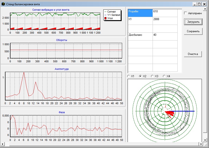
/ The program itself is at work /
If you look at the peaks in frequency, then you can see that two amplitudes are pronounced, as it turned out, one is responsible for the screw's vibration, and the second is created by an electric motor, as it is connected through the belt and spin faster. Thus, balancing the screw, we minimize the first peak, attaching a weight commensurate with the deviation of the circle on the opposite side.
Source: https://habr.com/ru/post/207478/
All Articles