Types of digital generators
In this article, I want to make a brief overview of the different methods of frequency generation, but first I will tell a few words about myself. This is my first article. I am a graduate student of the Moscow Energy Institute. He studied in the specialty "Metrology standardization and certification." This article was written primarily for myself, in order to find out what are the available methods for generating a signal, and since I did not find the squeeze of information in one place, I decided to make it myself and publish it here. All this is done for self-educational purposes. I will gladly accept comments on the text, in essence and style, in my personal mail, and will answer all your questions in the comments. I tried to write the article in the most accessible and simple language. So the types, and rather even the methods of generating a sinusoidal (and generally analog) signal. The first of these is called direct digital synthesis, or Direct Digital Synthesis.

A sinusoidal signal is, in fact, a solution to the equation Y = Sin (X), with a linearly varying argument X. To obtain a digital signal from a microcontroller, we need to apply the function values to a digital-to-analog converter (DAC). This means that in order to obtain a sinusoidal signal, we need to know the values of the function Y for each value of the argument X (in fact, X determines the value of the phase of the signal). You can calculate all the function values directly in the microcontroller, but to ensure high accuracy of the calculated values, a high-performance processor or a floating-point module is required. The calculation of the values in the microcontroller may take a long time, therefore, to ensure the speed of the calculations, they take ready-made values of the function and load them into memory. To ensure the smoothness of the output signal, to reduce the error associated with the nonlinearity characteristics of the digital-to-analog converter, as many sine values as possible are necessary. Thus, in memory there will be ready sine counts. In order for these counts to turn into a sine, they need to be somehow stretched in time so that each readout is fed to the DAC after a certain period of time after the previous one. This requires a reference frequency generator. Such a generator will produce pulses of constant duty cycle. These pulses, in the simplest case, arrive at the counter, and the counter, in turn, outputs a sequence of increasing codes. The code at the output of the counter will point to the next memory reference (ROM). ROM, in accordance with the codes, produces at its output the function values contained in the memory at these addresses, which are transmitted to the DAC and at the DAC output will be a sine with an ideal frequency. The frequency of the sine will correspond to the frequency of the clock generator. To ensure frequency tuning, the frequency of the reference oscillator must be regulated in some way. In the simplest case, a frequency divider is placed between the counter and the generator. Such a divider allows you to set the frequency within certain limits. The limit of tuning depends on the digit capacity of the adder and the frequency of the reference oscillator. The restructuring in this case will be possible only by certain values, since division is possible only by numbers that are multiples of 2.
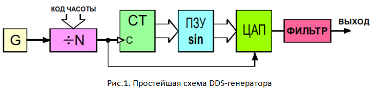
The simplest scheme of such a generator is shown in Figure 1. It includes a reference frequency generator (G). Divider into which the code of frequency (division factor), the counter (ST), ROM, a digital-to-analog converter and the filter is loaded. The filter in this case is necessary in order to smooth the digital signal at the output. A digital-to-analog converter is a digital device that provides only a certain level of signal. The lower the sampling rate, the more pronounced the step response of the output signal. In order to remove the error introduced by the sampling frequency, a signal filter is applied at the output. In the simplest case, this is a simple RC-chain, but it is necessary to take into account the speed characteristics of the DAC, since at high frequencies the useful signal can be filtered out.
Here is the simplest DDS scheme. Many elements in it can be replaced and refined. For example, if you replace the counter with a more complex device, the so-called battery phase, then we will have more opportunities, such as frequency tuning without phase shift or, for example, the ability to use a quarter of the period of sine values, instead of the full period, but in the framework of this article such complications will not be considered.
')
Now DDS are executed as separate chips. In such a chip, it is enough to load the parameters of the desired signal and connect the reference frequency generator, and at the output we will receive a digital sine wave, which you just need to filter with the specified parameters. Such generators can receive a frequency of up to 1.4 GHz. They, in turn, have one drawback. Direct digital synthesis generators are most often used precisely as frequency generators, so the amplitude of the output signal is not stable.
Another method of generating a sine wave signal using a controller is the PWM + passive RC filter method. PWM - pulse width modulation. It allows, by adjusting the pulse duty cycle, to obtain the desired constant amplitude of the signal. The wider the pulse, the higher the output voltage on the filter. Voltage can be changed from zero to supply voltage.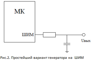 Thus, if you set a specific program for controlling the pulse duty cycle, then at the output you can receive a signal of any shape, including a sinusoidal signal. In the simplest case, the scheme is shown in Figure 2.
Such a generator is a cheap, and most importantly, the most easily implemented method of converting a digital signal into an analog signal using a microcontroller. It does not require special microcircuits or any complex circuit solutions. The only thing that is needed when creating such a generator is to calculate the output filter at a given cutoff frequency so that it does not cut off the useful signal. However, it is impossible to achieve high metrological characteristics on such a generator, since it is difficult to achieve a low harmonic distortion coefficient. A low level of harmonic distortion can be achieved using another version of the generator.
The third variant of the generator is based on a scheme called the “Wine Bridge”. The essence of this scheme is that an amplifier is used with two RC circuits in feedback. One serial and one parallel. The scheme of such a generator is shown in Figure 3.
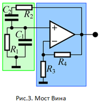
For this scheme, it is necessary to take into account the fact that the elements in the RC-chain must be strictly identical. Otherwise, the scheme will not be stable. Various tricks are used to reduce these effects, such as automatic gain control and other tricks. In the simplest case, the automatic control is carried out by some non-linear element, for example, a light bulb. But the restructuring of such a generator in frequency is difficult. It is necessary to use variable capacitors, which complicates the circuit by an order of magnitude. This method is good, but mainly for generating a specific frequency, or a frequency with a small adjustment range.
There are various options and modifications of the above schemes. In addition to these schemes, there are analog solutions that were not described here because of inconsistencies with the topic of the article. In conclusion, I want to say that each scheme should be chosen and worked out its possible implementation depending on the task that needs to be performed. My task is to create a precision sinusoidal signal generator, which can simultaneously produce a highly stable sinusoidal signal and add higher order harmonics to the signal. To perform this task, the best solution is to calculate the values of the sine function directly in the microcontroller with the transfer of values to the DAC. Such an implementation will allow me to take into account the shortcomings of each scheme and work out the technical implementation necessary specifically for my task. You can simultaneously make a stable amplitude, remove the harmonic distortion introduced by the feature of the circuit and get a fairly stable oscillator. And the final errors will depend only on what elements will be selected, and what degree of simplification of the algorithm is taken. Thus, with the immutability of the main structure, you can get a flexible solution to a certain class of problems.
If you are interested in any material on a similar topic, or in general something from the sphere of measuring devices and their design, then I could try to write some material to illuminate your question in a more simple and understandable way.
Sources:
1. DDS: direct digital synthesis frequency. Author: Ridiko L.I. [Electronic resource]: Article - http://www.digit-el.com/files/articles/dds.pdf - 12/25/2013
2. Test signal generator with a low level of harmonics on the Wien Bridge [Electronic resource]: Article - http://myelectrons.ru/wien-bridge-oscillator-low-thd/ - December 26, 2013
A sinusoidal signal is, in fact, a solution to the equation Y = Sin (X), with a linearly varying argument X. To obtain a digital signal from a microcontroller, we need to apply the function values to a digital-to-analog converter (DAC). This means that in order to obtain a sinusoidal signal, we need to know the values of the function Y for each value of the argument X (in fact, X determines the value of the phase of the signal). You can calculate all the function values directly in the microcontroller, but to ensure high accuracy of the calculated values, a high-performance processor or a floating-point module is required. The calculation of the values in the microcontroller may take a long time, therefore, to ensure the speed of the calculations, they take ready-made values of the function and load them into memory. To ensure the smoothness of the output signal, to reduce the error associated with the nonlinearity characteristics of the digital-to-analog converter, as many sine values as possible are necessary. Thus, in memory there will be ready sine counts. In order for these counts to turn into a sine, they need to be somehow stretched in time so that each readout is fed to the DAC after a certain period of time after the previous one. This requires a reference frequency generator. Such a generator will produce pulses of constant duty cycle. These pulses, in the simplest case, arrive at the counter, and the counter, in turn, outputs a sequence of increasing codes. The code at the output of the counter will point to the next memory reference (ROM). ROM, in accordance with the codes, produces at its output the function values contained in the memory at these addresses, which are transmitted to the DAC and at the DAC output will be a sine with an ideal frequency. The frequency of the sine will correspond to the frequency of the clock generator. To ensure frequency tuning, the frequency of the reference oscillator must be regulated in some way. In the simplest case, a frequency divider is placed between the counter and the generator. Such a divider allows you to set the frequency within certain limits. The limit of tuning depends on the digit capacity of the adder and the frequency of the reference oscillator. The restructuring in this case will be possible only by certain values, since division is possible only by numbers that are multiples of 2.
The simplest scheme of such a generator is shown in Figure 1. It includes a reference frequency generator (G). Divider into which the code of frequency (division factor), the counter (ST), ROM, a digital-to-analog converter and the filter is loaded. The filter in this case is necessary in order to smooth the digital signal at the output. A digital-to-analog converter is a digital device that provides only a certain level of signal. The lower the sampling rate, the more pronounced the step response of the output signal. In order to remove the error introduced by the sampling frequency, a signal filter is applied at the output. In the simplest case, this is a simple RC-chain, but it is necessary to take into account the speed characteristics of the DAC, since at high frequencies the useful signal can be filtered out.
Here is the simplest DDS scheme. Many elements in it can be replaced and refined. For example, if you replace the counter with a more complex device, the so-called battery phase, then we will have more opportunities, such as frequency tuning without phase shift or, for example, the ability to use a quarter of the period of sine values, instead of the full period, but in the framework of this article such complications will not be considered.
')
Now DDS are executed as separate chips. In such a chip, it is enough to load the parameters of the desired signal and connect the reference frequency generator, and at the output we will receive a digital sine wave, which you just need to filter with the specified parameters. Such generators can receive a frequency of up to 1.4 GHz. They, in turn, have one drawback. Direct digital synthesis generators are most often used precisely as frequency generators, so the amplitude of the output signal is not stable.
Another method of generating a sine wave signal using a controller is the PWM + passive RC filter method. PWM - pulse width modulation. It allows, by adjusting the pulse duty cycle, to obtain the desired constant amplitude of the signal. The wider the pulse, the higher the output voltage on the filter. Voltage can be changed from zero to supply voltage.
Thus, if you set a specific program for controlling the pulse duty cycle, then at the output you can receive a signal of any shape, including a sinusoidal signal. In the simplest case, the scheme is shown in Figure 2.Such a generator is a cheap, and most importantly, the most easily implemented method of converting a digital signal into an analog signal using a microcontroller. It does not require special microcircuits or any complex circuit solutions. The only thing that is needed when creating such a generator is to calculate the output filter at a given cutoff frequency so that it does not cut off the useful signal. However, it is impossible to achieve high metrological characteristics on such a generator, since it is difficult to achieve a low harmonic distortion coefficient. A low level of harmonic distortion can be achieved using another version of the generator.
The third variant of the generator is based on a scheme called the “Wine Bridge”. The essence of this scheme is that an amplifier is used with two RC circuits in feedback. One serial and one parallel. The scheme of such a generator is shown in Figure 3.
For this scheme, it is necessary to take into account the fact that the elements in the RC-chain must be strictly identical. Otherwise, the scheme will not be stable. Various tricks are used to reduce these effects, such as automatic gain control and other tricks. In the simplest case, the automatic control is carried out by some non-linear element, for example, a light bulb. But the restructuring of such a generator in frequency is difficult. It is necessary to use variable capacitors, which complicates the circuit by an order of magnitude. This method is good, but mainly for generating a specific frequency, or a frequency with a small adjustment range.
There are various options and modifications of the above schemes. In addition to these schemes, there are analog solutions that were not described here because of inconsistencies with the topic of the article. In conclusion, I want to say that each scheme should be chosen and worked out its possible implementation depending on the task that needs to be performed. My task is to create a precision sinusoidal signal generator, which can simultaneously produce a highly stable sinusoidal signal and add higher order harmonics to the signal. To perform this task, the best solution is to calculate the values of the sine function directly in the microcontroller with the transfer of values to the DAC. Such an implementation will allow me to take into account the shortcomings of each scheme and work out the technical implementation necessary specifically for my task. You can simultaneously make a stable amplitude, remove the harmonic distortion introduced by the feature of the circuit and get a fairly stable oscillator. And the final errors will depend only on what elements will be selected, and what degree of simplification of the algorithm is taken. Thus, with the immutability of the main structure, you can get a flexible solution to a certain class of problems.
If you are interested in any material on a similar topic, or in general something from the sphere of measuring devices and their design, then I could try to write some material to illuminate your question in a more simple and understandable way.
Sources:
1. DDS: direct digital synthesis frequency. Author: Ridiko L.I. [Electronic resource]: Article - http://www.digit-el.com/files/articles/dds.pdf - 12/25/2013
2. Test signal generator with a low level of harmonics on the Wien Bridge [Electronic resource]: Article - http://myelectrons.ru/wien-bridge-oscillator-low-thd/ - December 26, 2013
Source: https://habr.com/ru/post/207468/
All Articles