Laboratory installation on amateur electronics: from idea to finished machine
Hi, Habr!
I want to share my experience and talk about how I created a test set, ranging from the study of mechanics and the principle of electronics to the manufacture of a finished laboratory machine. The chip of the installation is that it is controlled by amateur electronics and is located at the junction of the DIY-device and the industrial design.
I studied at the Department of Materials Science in Mechanical Engineering, where new materials and coatings are being developed. As you know, one of the important indicators of the material is its durability. There are a number of GOSTs for various types of tests of wear resistance of materials. One of these GOST standards ( GOST 23.208-79 ) provides for testing materials on loosely fixed abrasive particles. Well, the trouble is: there is a standard, but nobody releases such installations. My task was to create an installation capable of conducting tests according to GOST plus accelerated tests under the conditions of the eternal “I need yesterday”. I want to tell you about the creation of such a machine ...
')
Functional analysis and technical study gave birth to the following scheme of the device operation.
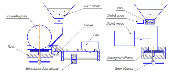
With the help of a clamp, the test sample is fixed in the lever. Moving the weight compensator according to the screw, the lever is set in an equilibrium state. By placing the calibrated weight into one of the holes in the lever, we press the sample against the roller with a known force. When the screw is rotated, the sand enters the zone of contact between the roller and the sample. The roller begins to rotate and rubs the sample. At the end of the test, the mass loss of the sample is measured. By weight loss, you can judge how much material is resistant to abrasive wear. Details of the test procedure described in GOST 23.208-79 .
The task, from the point of view of electronics, is quite simple - it is necessary to control 2 drives, keep a constant speed of rotation of a roller drive ± 2 r / min, count the number of revolutions of a roller. On completion of the specified number of cycles (roller revolutions), stop the test. It would also be nice to monitor the level of sand in the tank. On the part of the managers, many different options for implementing plant management were proposed. They all boiled down to something like this:
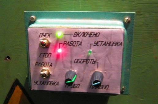
The image is taken from the site http://electronics-lab.ru
I also wanted to make the operator panel at the modern level, with a display, menus, various modes of operation and other goodies. The only problem was that I had never worked with microcontrollers, and, naturally, I would not have allocated money to develop a system on the side of the department. In search of simple and inexpensive solutions, I came across a domestic project Master KIT (currently the company has deactivated its profile from Habr) with a lot of ready-made solutions, lessons, examples, drivers and codes - everything that a newbie needs so much. It is worth noting that at that time I did not know about Arduino, otherwise I would have chosen him, as an even simpler and even cheaper solution.
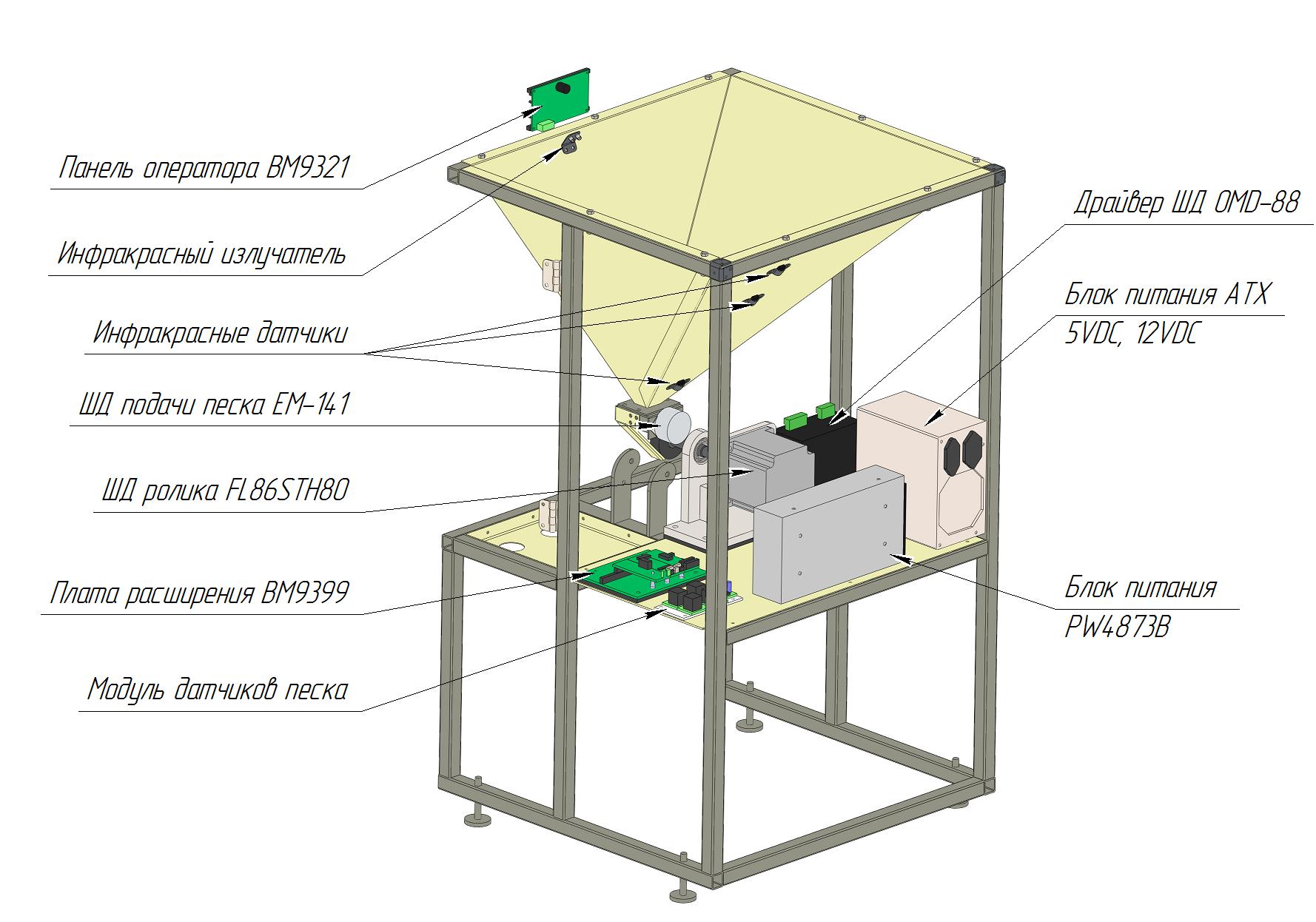
The main system management program will be stored in the Master KIT's BM9300H control module. This module has an onboard BASIC PIC interpreter, which allows noobs, like me, to program the system in an intuitive BASIC. Interaction with the system will be carried out through the operator panel BM9321 . The panel has a display and 8 buttons and communicates with the control module via RS485. The stepper motor will rotate the auger, and in turn, the BM9310 module will control the motor . To merge the modules, you need the BM9399 expansion card .
The rubber roller should rotate at a constant speed, despite the dynamically changing load (due to sand heterogeneity and other factors). In addition, it is necessary to provide a wide range of speeds from 30 to 240 rpm (for accelerated testing). The following options were considered:
We analyze in order:
According to the calculated moment, the FL86STH80 engine was chosen (then it cost 5,000 rubles) with the OMD-88 driver (4,200 rubles) and the PW4873B power supply unit (2,200 rubles). The control impulses for the OMD-88 will, again, be the BM9307 Kitov expansion module with the SD control program loaded on it.
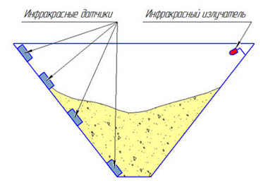
Another interesting task was to provide the operator with information on the amount of sand in the tank. You can, of course, make a transparent plexiglass tank and make sure that the sand does not end during the test, but this is not our approach. It is necessary to automate the process, in the case of an extremely low level of sand, to put the test to pause. The result was the following scheme:
Those. The principle of operation is extremely simple: if the sensor receives a signal from the radiator, there is no sand at this level. For management of all this economy I soldered a separate fee - “Sand Sensor Module”.
The result was this scheme:

And it will be located in the body approximately like this:
The prototype is the thing needed to identify all possible underwater rakes at an early stage. But what can I say - the scheme may be generally inoperative. In general, a prototype was assembled from aluminum corners, wooden bars and handy materials.
I agree, the prototype turned out to be poor, but I fulfilled my tasks: I revealed many problems and presented invaluable experience. The most important thing at this stage is not to leave everything as it is, gather strength and bring things to mind. So, let's continue ...
The body of the car is like the body of a woman; this is the first thing that attracts attention. Therefore, the body should be attractive and charming. With the help of SolidWorks, I created 2 models, the first one designed for making a body made of plastic or fiberglass, the second one - for bending steel sheet. For general presentation: dimensions of the designed machine are 500x500x900 mm.
The first version of the case looks quite aesthetically pleasing, but it will be very expensive to manufacture such panels or, in the case of production from fiberglass, it is very laborious. The plastic version may be suitable for a serial copy, when the cost of the form is broken. Therefore, the steel case definitely wins. Now the market is filled with many enterprises engaged in laser cutting and sheet bending. Moreover, the bending is carried out very accurate and accurate, and most importantly inexpensive (about 20 rubles per die depending on the thickness of the sheet, seriality and greed).
For the manufacture of the installation were made drawings of all parts and assemblies in SolidWorks. The drawings are associative with a 3D model, which greatly simplifies life, i.e. when adjustments are made to the model, and in the development process they are made very often, the drawings are rebuilt automatically, well, or with minimal modifications. Production installation can be divided into the following stages:
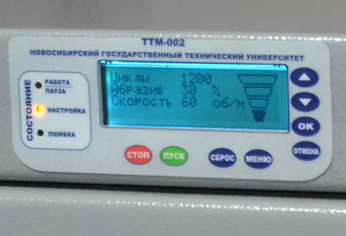
After all the welding, assembly, grinding and finishing work, the installation was disassembled to the screw and all the details were given for polymer painting. Then, of course, collected again. The result was such an installation with the intelligent name of the TTM-002 tribotechnical machine. Two - because the second after the prototype.

In order not to scroll up, I post the photo of the operator panel again. Before starting work, the operator adjusts the number of cycles in the test, the speed of rotation of the roller and the feed rate of sand as a percentage of the maximum value. The right side of the display shows the level of sand. In the menu, you can select different modes of operation and change the settings. For example, the mode “Without sand supply” may be needed for burnishing the roller or the mode “Without rotation of the roller” - for quickly dumping the contents of the tank.
In total, approximately 45,000 rubles was spent on the installation, of course, not counting my work and the work of my colleagues, who helped me with its manufacture. A lot of effort has been invested. The whole process from idea to finished installation took 2 years (2010-2012), but it was with long breaks for several months, plus the last year I worked at the factory, and I was engaged in installation after work and on weekends. It is worth noting that each purchase of components is a whole epic, which takes a lot of time and gives a lot of headaches (those who did shopping through the university will surely understand me). The fact is that state institutionsdo not cooperate with e-bay on 30% prepayment, which even a Russian company will not do. There are, of course, the left schemes of payment options with the kind of shipment, but we will not talk about this. At present, the unit is working at the Department of Materials Science in Mechanical Engineering of the Novosibirsk State Technical University, testing nanomaterials, in general, serves for the benefit of domestic science.
In order not to turn the article into a three-volume book, I did not describe in detail many things. However, I will be glad to answer your questions and add details.
I want to share my experience and talk about how I created a test set, ranging from the study of mechanics and the principle of electronics to the manufacture of a finished laboratory machine. The chip of the installation is that it is controlled by amateur electronics and is located at the junction of the DIY-device and the industrial design.
I studied at the Department of Materials Science in Mechanical Engineering, where new materials and coatings are being developed. As you know, one of the important indicators of the material is its durability. There are a number of GOSTs for various types of tests of wear resistance of materials. One of these GOST standards ( GOST 23.208-79 ) provides for testing materials on loosely fixed abrasive particles. Well, the trouble is: there is a standard, but nobody releases such installations. My task was to create an installation capable of conducting tests according to GOST plus accelerated tests under the conditions of the eternal “I need yesterday”. I want to tell you about the creation of such a machine ...
')
Functional analysis and technical study gave birth to the following scheme of the device operation.
With the help of a clamp, the test sample is fixed in the lever. Moving the weight compensator according to the screw, the lever is set in an equilibrium state. By placing the calibrated weight into one of the holes in the lever, we press the sample against the roller with a known force. When the screw is rotated, the sand enters the zone of contact between the roller and the sample. The roller begins to rotate and rubs the sample. At the end of the test, the mass loss of the sample is measured. By weight loss, you can judge how much material is resistant to abrasive wear. Details of the test procedure described in GOST 23.208-79 .
Control electronics
The task, from the point of view of electronics, is quite simple - it is necessary to control 2 drives, keep a constant speed of rotation of a roller drive ± 2 r / min, count the number of revolutions of a roller. On completion of the specified number of cycles (roller revolutions), stop the test. It would also be nice to monitor the level of sand in the tank. On the part of the managers, many different options for implementing plant management were proposed. They all boiled down to something like this:
The image is taken from the site http://electronics-lab.ru
I also wanted to make the operator panel at the modern level, with a display, menus, various modes of operation and other goodies. The only problem was that I had never worked with microcontrollers, and, naturally, I would not have allocated money to develop a system on the side of the department. In search of simple and inexpensive solutions, I came across a domestic project Master KIT (currently the company has deactivated its profile from Habr) with a lot of ready-made solutions, lessons, examples, drivers and codes - everything that a newbie needs so much. It is worth noting that at that time I did not know about Arduino, otherwise I would have chosen him, as an even simpler and even cheaper solution.
The main system management program will be stored in the Master KIT's BM9300H control module. This module has an onboard BASIC PIC interpreter, which allows noobs, like me, to program the system in an intuitive BASIC. Interaction with the system will be carried out through the operator panel BM9321 . The panel has a display and 8 buttons and communicates with the control module via RS485. The stepper motor will rotate the auger, and in turn, the BM9310 module will control the motor . To merge the modules, you need the BM9399 expansion card .
Selection of drive roller
The rubber roller should rotate at a constant speed, despite the dynamically changing load (due to sand heterogeneity and other factors). In addition, it is necessary to provide a wide range of speeds from 30 to 240 rpm (for accelerated testing). The following options were considered:
- Asynchronous gearmotor with frequency converter.
- DC collector motor with PWM control and feedback on the sensor.
- Stepper motor with control unit.
We analyze in order:
- Asynchronous gearmotor with chastotnik - a good thing. The frequency converter can maintain a constant rotational speed with current feedback without sensors at the output. However, in our case, the sensor will still be needed to count the number of revolutions. The wide speed range is also not a question. Only such an assembly is not cheap, only one 180 W gear motor will cost about 15,000 rubles .
- DC motor-reducer will cost about as well as an asynchronous. But here it is necessary to work with the support of a constant speed with feedback on the sensor. It is also complicated by the provision of a large range of speeds.
- A stepper motor will cost less due to the lack of a gear unit, and it will perform its functions 100%, will relieve you of problems with speed control and speed counting. How many steps set - so much the motor turned - easy money. Minus SD in low efficiency, there are also problems with vibration, but they can be partially solved with vibration-damping pads. On the stepper motor, we stop.
According to the calculated moment, the FL86STH80 engine was chosen (then it cost 5,000 rubles) with the OMD-88 driver (4,200 rubles) and the PW4873B power supply unit (2,200 rubles). The control impulses for the OMD-88 will, again, be the BM9307 Kitov expansion module with the SD control program loaded on it.
Sand level sensors
Another interesting task was to provide the operator with information on the amount of sand in the tank. You can, of course, make a transparent plexiglass tank and make sure that the sand does not end during the test, but this is not our approach. It is necessary to automate the process, in the case of an extremely low level of sand, to put the test to pause. The result was the following scheme:
Those. The principle of operation is extremely simple: if the sensor receives a signal from the radiator, there is no sand at this level. For management of all this economy I soldered a separate fee - “Sand Sensor Module”.
Circuit diagram
The result was this scheme:
And it will be located in the body approximately like this:
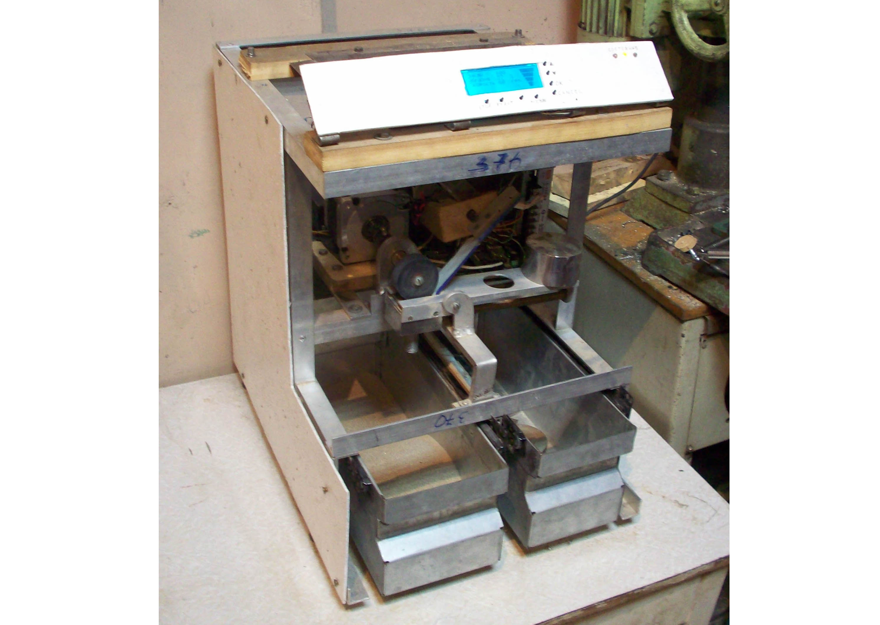
Prototype build
The prototype is the thing needed to identify all possible underwater rakes at an early stage. But what can I say - the scheme may be generally inoperative. In general, a prototype was assembled from aluminum corners, wooden bars and handy materials.
I agree, the prototype turned out to be poor, but I fulfilled my tasks: I revealed many problems and presented invaluable experience. The most important thing at this stage is not to leave everything as it is, gather strength and bring things to mind. So, let's continue ...
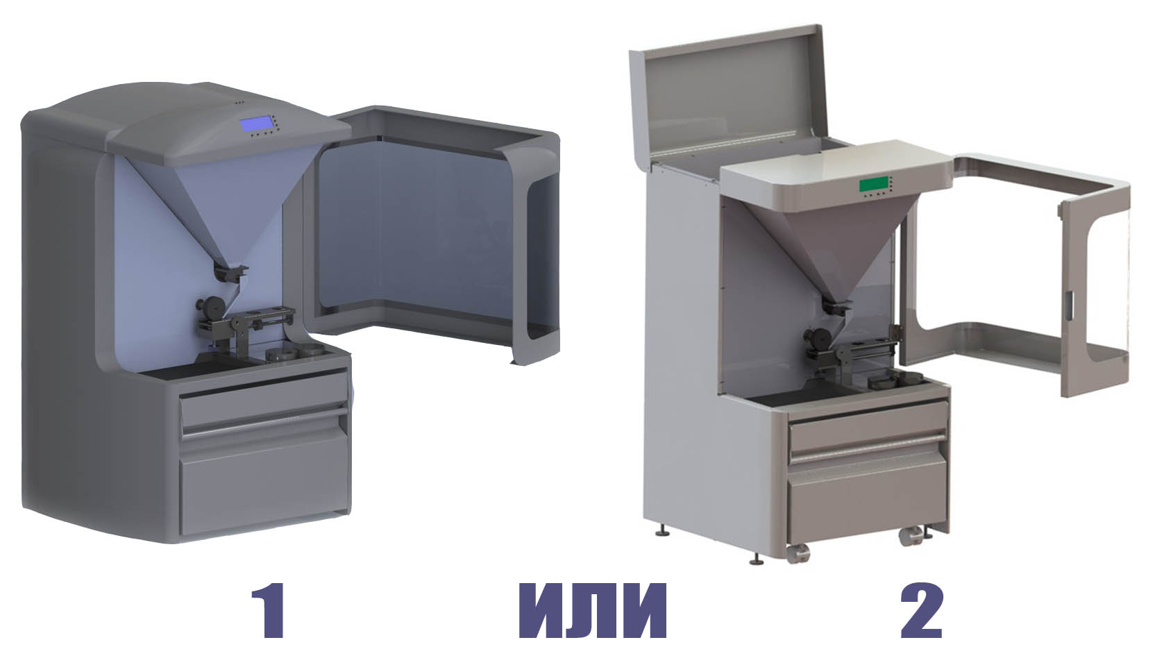
The choice of body type
The body of the car is like the body of a woman; this is the first thing that attracts attention. Therefore, the body should be attractive and charming. With the help of SolidWorks, I created 2 models, the first one designed for making a body made of plastic or fiberglass, the second one - for bending steel sheet. For general presentation: dimensions of the designed machine are 500x500x900 mm.
The first version of the case looks quite aesthetically pleasing, but it will be very expensive to manufacture such panels or, in the case of production from fiberglass, it is very laborious. The plastic version may be suitable for a serial copy, when the cost of the form is broken. Therefore, the steel case definitely wins. Now the market is filled with many enterprises engaged in laser cutting and sheet bending. Moreover, the bending is carried out very accurate and accurate, and most importantly inexpensive (about 20 rubles per die depending on the thickness of the sheet, seriality and greed).
Production
For the manufacture of the installation were made drawings of all parts and assemblies in SolidWorks. The drawings are associative with a 3D model, which greatly simplifies life, i.e. when adjustments are made to the model, and in the development process they are made very often, the drawings are rebuilt automatically, well, or with minimal modifications. Production installation can be divided into the following stages:
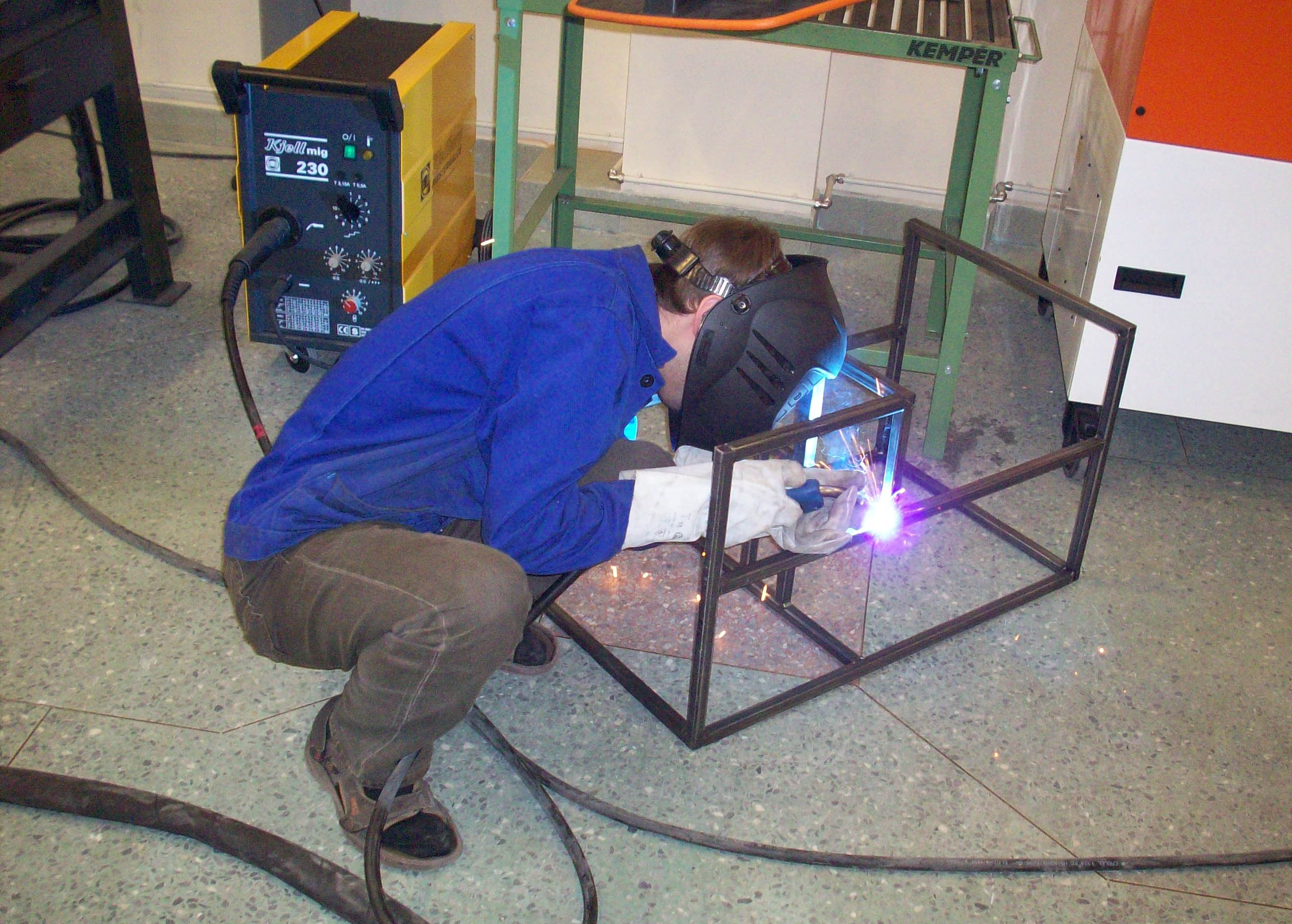
- Making a frame. The frame was made of steel square pipes welded together. Assembling the frame of the pipes is quite simple, but you should not underestimate this stage. In the case of inaccurate frame dimensions or its shape, the cover may not fit, the door will not close, the drawer will not drop in, and other interesting surprises will definitely come out during assembly. Therefore, the pipes were cut with an allowance, and then milled along the ends into the required size within a tolerance of ± 0.5 mm with ensuring perpendicularity relative to the wall.
- Turning and milling parts (engine rack, lever arm, auger body, shaft, coupling and weights) were manufactured at our same department. For such things, the university has all the necessary equipment. Modern machines and people with hands give details of excellent quality at the exit without the need for a file.
- The sheet metal parts (body, doors, tank, box for waste sand, lever and various small things such as brackets, plates, etc.) are laser cut and bent to order. Together with the material, these parts cost about 5,000 rubles. True, designer feints in the form of rounding with a large radius had to bend by hand. But this is not a difficult matter, steel sheet with a thickness of 1 mm is quite malleable.
- Plexiglas window. Plexiglas had to be bent along the radius so that its shape coincided with the shape of the door. Plexiglas was also a very pliable material, as soon as an industrial hairdryer came to the rescue.
- False panel is a sticker with transparent windows for the display and LEDs. The sticker was also made for the order, for this it was necessary to draw it in a vector and pay only 977 rubles. for 5 stickers. Although only one sticker was needed, the difference in price for 1 and 5 pieces was insignificant. Just in case I ordered 5.
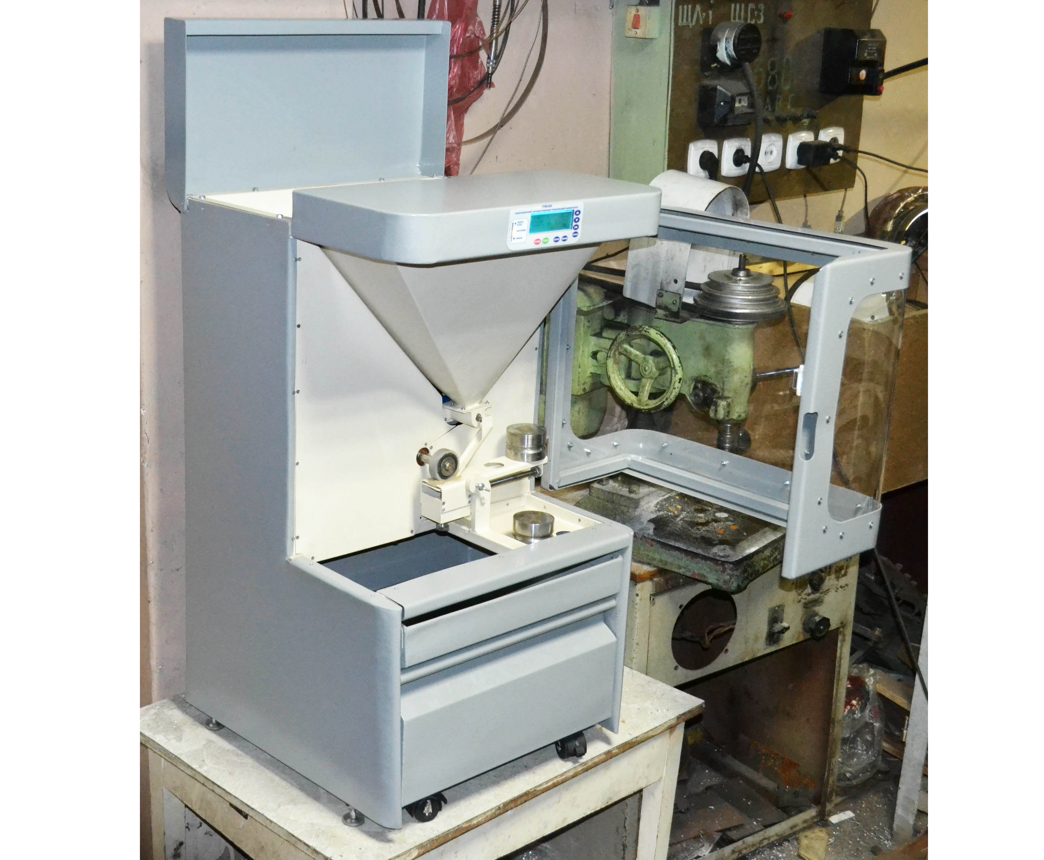
Total
After all the welding, assembly, grinding and finishing work, the installation was disassembled to the screw and all the details were given for polymer painting. Then, of course, collected again. The result was such an installation with the intelligent name of the TTM-002 tribotechnical machine. Two - because the second after the prototype.
In order not to scroll up, I post the photo of the operator panel again. Before starting work, the operator adjusts the number of cycles in the test, the speed of rotation of the roller and the feed rate of sand as a percentage of the maximum value. The right side of the display shows the level of sand. In the menu, you can select different modes of operation and change the settings. For example, the mode “Without sand supply” may be needed for burnishing the roller or the mode “Without rotation of the roller” - for quickly dumping the contents of the tank.
In total, approximately 45,000 rubles was spent on the installation, of course, not counting my work and the work of my colleagues, who helped me with its manufacture. A lot of effort has been invested. The whole process from idea to finished installation took 2 years (2010-2012), but it was with long breaks for several months, plus the last year I worked at the factory, and I was engaged in installation after work and on weekends. It is worth noting that each purchase of components is a whole epic, which takes a lot of time and gives a lot of headaches (those who did shopping through the university will surely understand me). The fact is that state institutions
In order not to turn the article into a three-volume book, I did not describe in detail many things. However, I will be glad to answer your questions and add details.
Source: https://habr.com/ru/post/207388/
All Articles