Implementation of the I2C interface based on the FT2232H chip (MPSSE mode)
The interface chip supports operation with the I2C interface (not to be confused with the I2S!) In the MPSSE (Multi-Protocol Synchronous Serial Engine) mode. In addition to I2C, this mode supports a whole list of standard serial interfaces, such as SPI, JTAG, etc. It is possible to implement your own interfaces if necessary. This description tells about a number of nuances of I2C interface support, and also gives a reason to chat on related topics.
Disclaimer: this article is written on working materials and is primarily intended for the author of the article when he loses the original document. At the same time, the information given below may be of interest to a narrow circle of specialists. Not recommended for reading to a wide range of readers except when the reader wants to briefly plunge into the world of debugging software and hardware. Studies were conducted more than a year ago, but this information remains relevant at the moment, since the libraries on the manufacturer’s website have not been updated. Information about the detected problems was sent to the manufacturer, but no feedback followed. A post was written based on this , for which the author is expressed a special thanks
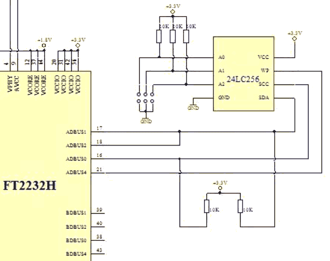
The independent operation of two I2C channels is supported (one channel for FT232H). An example of the wiring diagram is given in AN113 - the communication between the FT2232H and the 24LC256 non-volatile memory chip is used as an example. Directly to the I2C interface are only two signals: SCL (clock signal, in the figure referred to as SCC) and SDA (transmitted data). According to the specification, each of these signals can be bidirectional, however, often only one master device (master) is present on the bus, and it is this that sets the clock signal. Data is in any case bidirectional - for every 8 bits of transmitted data, 1 acknowledgment bit follows.
At the program level, I2C bus operation is possible in two ways:
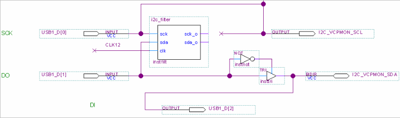
Studies were conducted using one of the available boards. The INA219 power meter was used as the slave device on the I2C bus. Since the board was taken by the one that was on hand, between the FT2232H and INA219 microcircuits was FPGA ( I was lucky, I realized a little later ). Initially, I planned to use it only to convert the 3-wire interface of the FT2232H to the two-wire I2C bus interface - in a normal device, this conversion takes place at the expense of the circuit, see the figure above.
')
As already written, the transmission of data for every 8 bits of information transmitted is followed by an acknowledgment (ACK) —the transfer of the signal to state 0 from the receiving device. If the transmitting device sees this confirmation, it means that it has been heard and can be continued further. If there is no confirmation, then it is no use to continue further and the exchange can be stopped.
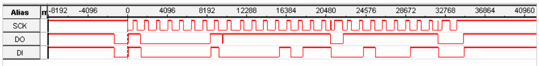
During the research it was found that the library LibMPSSE-I2C has an error that blocks the ability to read more than one byte on the bus in most cases. The error is manifested by the occurrence of a glitch on the clock signal before setting the ACK confirmation of the first byte read from the FT2232H side to the bus. The glitch length is 1 period of the frequency of 12 MHz (about 8 ns). This glitch is perceived by the slave device on the bus as a clock signal appearing at the moment when the ACK flag is not yet set. After that, the slave device aborts the transaction. An example of such a transaction, within which an attempt is made to read two bytes from the device, is shown in the figures (data was captured at a frequency of 120 MHz, the glitch is present at time counts 20968-20967). Timing diagrams are obtained using the SignalTap embedded logic analyzer for Alter FPGAs ( here I was glad for the first time to see a FPGA that was busy). The pictures show that the DI reads the first byte from the device, then the device falls off (having received an incorrect confirmation from the master) and 0xFF is read instead of the second byte.

In the case of filtering this pulse, the correct bus reading procedure was provided. In the test environment, filtering was done on the FPGA in a digital way ( a small module on VHDL was written, discarding glitches on the input signals ). Another possible method is filtering using an RC chain on an SCL bus, however this will limit the maximum frequency of the bus ( due to some insanity, this solution has not been deeply analyzed ). An example of a successful transaction (subject to filtering glitch) is shown in the following figure. Now on the DI bus we see the correct reading of two bytes.
Naturally, I want to get to the true causes of this behavior. Unfortunately, the source code of the library LibMPSSE-I2C is not available, disassembling binaries is not our specialty. But to analyze the USB data exchange in the presence of an open protocol description is a matter of 5 minutes. Well, an hour. Well, no more than a day.
A detailed study showed a problem in the formation of commands for the MPSSE controller generated by the library LibMPSSE-I2C. The following is a set of commands used to read 2 bytes on the bus (the stop bit is not set at the end). Dedicated commands show the location of the problem and the way to solve it (prohibiting the transition to 1 or changing the phase of the applied clock signal for the ACK sign):
Thus, the problem is localized, a solution is found and all the suffering are divided into 3 streams:
In the process of research, two test software projects have been created, based on examples supplied by FTDI. The project based on the library LibMPSSE-I2C is called i2c_direct (the main file is i2c_direct.cpp). The project programming the MPSSE mode itself is I2CTEST (the main file I2CTEST.cpp). Those who wish will find examples of source files in the rarjpeg archive in the first picture of the post.
References:
AN108 Command Processor For MPSSE and MCU Host Bus Emulation Modes
AN113 Interfacing FT2232H Hi-Speed Devices To I2C Bus
AN177 User Guide For LibMPSSE-I2C
Example of interface FT2232H Hi-Speed devices to I2C bus (via D2XX)
LibMPSSE-I2C Examples
Disclaimer: this article is written on working materials and is primarily intended for the author of the article when he loses the original document. At the same time, the information given below may be of interest to a narrow circle of specialists. Not recommended for reading to a wide range of readers except when the reader wants to briefly plunge into the world of debugging software and hardware. Studies were conducted more than a year ago, but this information remains relevant at the moment, since the libraries on the manufacturer’s website have not been updated. Information about the detected problems was sent to the manufacturer, but no feedback followed. A post was written based on this , for which the author is expressed a special thanks
The independent operation of two I2C channels is supported (one channel for FT232H). An example of the wiring diagram is given in AN113 - the communication between the FT2232H and the 24LC256 non-volatile memory chip is used as an example. Directly to the I2C interface are only two signals: SCL (clock signal, in the figure referred to as SCC) and SDA (transmitted data). According to the specification, each of these signals can be bidirectional, however, often only one master device (master) is present on the bus, and it is this that sets the clock signal. Data is in any case bidirectional - for every 8 bits of transmitted data, 1 acknowledgment bit follows.
At the program level, I2C bus operation is possible in two ways:
- Directly through the driver D2XX. In this case, you must manually program the MPSSE mode in accordance with the instruction set described in AN108. All work goes through the functions FT_Read () and FT_Write (), as well as the associated functions of opening / closing the device, etc.
- Using the library LibMPSSE-I2C. This library solves all the issues of programming the MPSSE mode and allows reading and writing operations of the specified number of bytes on the I2C bus using the I2C_DeviceWrite () and I2C_DeviceRead () calls. Library descriptions are provided in AN177.
Studies were conducted using one of the available boards. The INA219 power meter was used as the slave device on the I2C bus. Since the board was taken by the one that was on hand, between the FT2232H and INA219 microcircuits was FPGA ( I was lucky, I realized a little later ). Initially, I planned to use it only to convert the 3-wire interface of the FT2232H to the two-wire I2C bus interface - in a normal device, this conversion takes place at the expense of the circuit, see the figure above.
')
As already written, the transmission of data for every 8 bits of information transmitted is followed by an acknowledgment (ACK) —the transfer of the signal to state 0 from the receiving device. If the transmitting device sees this confirmation, it means that it has been heard and can be continued further. If there is no confirmation, then it is no use to continue further and the exchange can be stopped.
During the research it was found that the library LibMPSSE-I2C has an error that blocks the ability to read more than one byte on the bus in most cases. The error is manifested by the occurrence of a glitch on the clock signal before setting the ACK confirmation of the first byte read from the FT2232H side to the bus. The glitch length is 1 period of the frequency of 12 MHz (about 8 ns). This glitch is perceived by the slave device on the bus as a clock signal appearing at the moment when the ACK flag is not yet set. After that, the slave device aborts the transaction. An example of such a transaction, within which an attempt is made to read two bytes from the device, is shown in the figures (data was captured at a frequency of 120 MHz, the glitch is present at time counts 20968-20967). Timing diagrams are obtained using the SignalTap embedded logic analyzer for Alter FPGAs ( here I was glad for the first time to see a FPGA that was busy). The pictures show that the DI reads the first byte from the device, then the device falls off (having received an incorrect confirmation from the master) and 0xFF is read instead of the second byte.
In the case of filtering this pulse, the correct bus reading procedure was provided. In the test environment, filtering was done on the FPGA in a digital way ( a small module on VHDL was written, discarding glitches on the input signals ). Another possible method is filtering using an RC chain on an SCL bus, however this will limit the maximum frequency of the bus ( due to some insanity, this solution has not been deeply analyzed ). An example of a successful transaction (subject to filtering glitch) is shown in the following figure. Now on the DI bus we see the correct reading of two bytes.
Naturally, I want to get to the true causes of this behavior. Unfortunately, the source code of the library LibMPSSE-I2C is not available, disassembling binaries is not our specialty. But to analyze the USB data exchange in the presence of an open protocol description is a matter of 5 minutes. Well, an hour. Well, no more than a day.
A detailed study showed a problem in the formation of commands for the MPSSE controller generated by the library LibMPSSE-I2C. The following is a set of commands used to read 2 bytes on the bus (the stop bit is not set at the end). Dedicated commands show the location of the problem and the way to solve it (prohibiting the transition to 1 or changing the phase of the applied clock signal for the ACK sign):
0x80, 0x03, 0x13, 0x80, 0x03, 0x13, 0x80, 0x03, 0x13, 0x80, 0x03, 0x13, 0x80, 0x03, 0x13, // SDA, SCL high 0x80, 0x03, 0x13, 0x80, 0x03, 0x13, 0x80, 0x03, 0x13, 0x80, 0x03, 0x13, 0x80, 0x03, 0x13, 0x80, 0x01, 0x13, 0x80, 0x01, 0x13, 0x80, 0x01, 0x13, 0x80, 0x01, 0x13, 0x80, 0x01, 0x13, // SDA low: START 0x80, 0x01, 0x13, 0x80, 0x01, 0x13, 0x80, 0x01, 0x13, 0x80, 0x01, 0x13, 0x80, 0x01, 0x13, 0x80, 0x01, 0x13, 0x80, 0x01, 0x13, 0x80, 0x01, 0x13, 0x80, 0x01, 0x13, 0x80, 0x01, 0x13, 0x80, 0x01, 0x13, 0x80, 0x01, 0x13, 0x80, 0x01, 0x13, 0x80, 0x01, 0x13, 0x80, 0x01, 0x13, 0x80, 0x00, 0x13, // SDA, SCL low 0x80, 0x02, 0x13, // SDA high, SCL low 0x13, 0x07, 0x81, // Write address 0x80, 0x00, 0x11, // SDA, SCL low 0x22, 0x00, // Read ACK from slave 0x80, 0x00, 0x11, // SDA, SCL low 0x22, 0x07, // Read 8 bits 0x80, 0x02, 0x13, // SDA high, SCL low //0x80, 0x00, 0x13, // Optional fix (use instead prev. command) to avoid SDA to go High //0x12, 0x00, 0x00, // Write 1 bit: ACK - error here in LibMPSSE-I2C 0x13, 0x00, 0x00, // Write 1 bit: ACK - fixed version ************************************* 0x80, 0x00, 0x11, 0x22, 0x07, 0x80, 0x02, 0x13, 0x12, 0x00, 0x00 Thus, the problem is localized, a solution is found and all the suffering are divided into 3 streams:
- Communicate with FTDI about the above, pending clarification.
- They disassemble the binary library in search of the place where the corresponding teams are formed and rule it.
- They write without using LibMPSSE-I2C library, directly sending control sequences similar to those listed above, thereby programming the MPSSE mode bypassing the library.
In the process of research, two test software projects have been created, based on examples supplied by FTDI. The project based on the library LibMPSSE-I2C is called i2c_direct (the main file is i2c_direct.cpp). The project programming the MPSSE mode itself is I2CTEST (the main file I2CTEST.cpp). Those who wish will find examples of source files in the rarjpeg archive in the first picture of the post.
References:
AN108 Command Processor For MPSSE and MCU Host Bus Emulation Modes
AN113 Interfacing FT2232H Hi-Speed Devices To I2C Bus
AN177 User Guide For LibMPSSE-I2C
Example of interface FT2232H Hi-Speed devices to I2C bus (via D2XX)
LibMPSSE-I2C Examples
Source: https://habr.com/ru/post/207214/
All Articles