Holiday geeky: with ARM and TFT LCD
Introduction
 Having seen posts from dlinyj , goodic and Hoshi, I once again felt that Habr is a cake.
The first post concerned writing a character driver based on the HD44780 for Linux ( Creating your own Linux drivers from dlinyj ); The excellent answers to it were the posts of goodic habrauers ( Congratulations on geeks, without writing firewood ) and Hoshi ( New Year raspberry - fastening the HD44780 screen to Raspberry Pi ).
I also wanted to participate in this celebration of life and implement my hardware
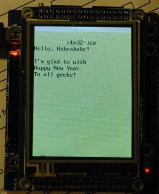
vt52-like terminal. I didn't have a character display, but there was a Chinese dev-board based on ARM Cortex-M3 with a full TFT-display 240x320, partial documentation.')
There was a lot of enthusiasm, so, waking up on Sunday afternoon (~ 17 MSK), I began to write the embedded driver for this LCD.
If you are interested in embedded ARM programming, electronics or just the result, I ask for cat.
Iron
I had a simple debug board from the Middle Kingdom (costing about $ 20) based on an ST STM32F103RB microcontroller with a USB-to-UART Prolific PL-2303HX hardware bridge, a bunch of small peripherals and a TFT LCD with an Ilitek ILI9320 controller with an unknown wiring diagram.
Olimex JTAG ARM-TINY-USB-H was used as an in-circuit debugger and programmer. Good device, it works fine with OpenOCD .
devboard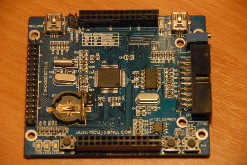
More precisely, initially it was not even known what the controller is on the LCD. All that could be learned from the display module, that it is connected via a 16-bit bus, has
nCS , nWR , nRD , BL_EN and RS signals,the purpose of which was not difficult to guess:
nCS- bus display activation (hereinafter the prefixnmeans that the active signal level is 0)BL_EN- backlight controlnWR- recordsnRD- readingRS- register selection
In one of the archives with the documentation found on the open spaces of the Chinese segment of the Internet there was a similar fee to
module Ilitek 932x.
Software interfaces
Low-level interface
Since there are not many descriptions of work with this LCD controller in Runet, I will probably describe a low-level interface.
In essence, this controller has 4: i80-system (parallel interface, a-la regular memory, similar to HD44780 interface), SPI, VSYNC (system +
VSYNC , with internal clock) and RGB ( VSYNC , HSYNC , ENABLE , with external DOTCLK clocking). In my case, i80-system is available and, possibly, SPI (did not check).Since I used only the system, we’ll do its description. In order not to load much into the article - it will be in the spoiler.
Electrical interface ILI9320
At the electrical level, working with digital technology is usually described by timing charts. In our case, there are five control signals and a 16-bit data bus.
Before transmitting any information to the
Further, with the
After that, the actual read or write operation is performed (using
Diagrams of these processes are as follows:
When writing / reading from GRAM, a special register
addresses GRAM, which allows you to read / write its contents sequentially.
Charts:
After performing operations,
For drawing timing charts, I found a wonderful wavedrom project running in a browser. Test here (here the schemes were prepared above).
Before transmitting any information to the
nCS , the interface should be activated by the nCS signal, setting it to 0.Further, with the
RS set to 0, the register address is written into which information will be written (the actual recording is performed by activating the nWR signal. The RS signal is set back to 1.After that, the actual read or write operation is performed (using
nRD and nWR respectively).Diagrams of these processes are as follows:
| op | |
|---|---|
| read |  |
| write |  |
When writing / reading from GRAM, a special register
0x22 . In addition, the controller can auto-incrementaddresses GRAM, which allows you to read / write its contents sequentially.
Charts:
| op | |
|---|---|
| GRAM read |  |
| GRAM write |  |
After performing operations,
nCS set back to 1.For drawing timing charts, I found a wonderful wavedrom project running in a browser. Test here (here the schemes were prepared above).
Low-level functions were written based on the electrical interface:
lcd_ll_funcs
void _lcd_select(void) { GPIO_ResetBits(GPIOC, GPIO_Pin_9); } void _lcd_deselect(void) { GPIO_SetBits(GPIOC, GPIO_Pin_9); } void _lcd_rs_set(void) { GPIO_SetBits(GPIOC, GPIO_Pin_8); } void _lcd_rs_reset(void) { GPIO_ResetBits(GPIOC, GPIO_Pin_8); } void _lcd_rd_en(void) { GPIO_ResetBits(GPIOC, GPIO_Pin_11); } void _lcd_rd_dis(void) { GPIO_SetBits(GPIOC, GPIO_Pin_11); } void _lcd_wr_en(void) { GPIO_ResetBits(GPIOC, GPIO_Pin_10); } void _lcd_wr_dis(void) { GPIO_SetBits(GPIOC, GPIO_Pin_10); } void _lcd_bl_en(void) { GPIO_SetBits(GPIOC, GPIO_Pin_12); } void _lcd_bl_dis(void) { GPIO_ResetBits(GPIOC, GPIO_Pin_12); } // changes DB[15:0] GPIO pins mode void lcd_gpio_conf(GPIOMode_TypeDef mode); void _lcd_put_data(u16 data) { // data[0-7] -> GPIOC[0-7], data[8-15] -> GPIOB[8-15] GPIOB->ODR = (GPIOB->ODR&0x00ff)|(data&0xff00); GPIOC->ODR = (GPIOC->ODR&0xff00)|(data&0x00ff); } u16 _lcd_read_data(void) { lcd_gpio_conf(GPIO_Mode_IN_FLOATING); u16 result = (GPIOB->IDR&0xff00)|(GPIOC->IDR&0x00ff); lcd_gpio_conf(GPIO_Mode_Out_PP); return result; } // assume that lcd_select() was done before it void _lcd_tx_reg(u8 addr) { _lcd_put_data(addr); _lcd_rs_reset(); _lcd_wr_en(); _lcd_wr_dis(); _lcd_rs_set(); } // assume that _lcd_tx_reg(u8) was done before it void _lcd_tx_data(u16 data) { _lcd_put_data(data); _lcd_wr_en(); _lcd_wr_dis(); } // assume that _lcd_tx_reg(u8) was done before it u16 _lcd_rx_data(void) { _lcd_rd_en(); u16 result = _lcd_read_data(); _lcd_rd_dis(); return result; } To speed up, you can zainlaynit these functions and convert to macros (with which Eclipse is not very friendly, unfortunately).
Based on these functions, the functions of writing to the register, reading from the register, blitting the image are implemented.
High-level interface
The functions of the LCD display for the main part of the program are available through the following API:
u16 lcd_init(void); void lcd_set_cursor(u16 x, u16 y); void lcd_set_window(u16 left, u16 top, u16 right, u16 bottom); void lcd_fill(u32 color); void lcd_rect(u16 left, u16 top, u16 right, u16 bottom); void lcd_put_char_at(u32 data, u16 x, u16 y); u32 lcd_get_fg(void); u32 lcd_get_bg(void); void lcd_set_fg(u32 color); void lcd_set_bg(u32 color); Terminal functions use this interface for all their operations.
The most interesting part is the function of drawing a symbol, since it hides all the work with fonts. It looks like this:
lcd_put_char_at
void lcd_put_char_at(u32 data, u16 x, u16 y) { u8 xsize, ysize; u8 *char_img; lcd_get_char(data, &xsize, &ysize, &char_img); lcd_set_cursor(x, y); lcd_set_window(x, y, x + xsize, y + ysize); _lcd_select(); _lcd_tx_reg(0x22); // works only for 8xN fonts for(u8 i = 0; i < ysize; i++) { u8 str = char_img[i]; for(u8 j = 0; j < xsize; j++) { _lcd_tx_data((str&(1<<(xsize-j-1)))?fg_color:bg_color); } } _lcd_deselect(); } As you can see, the link to the character bitmap and its size comes from the
lcd_get_char function by the character code (it is 32-bit, so that the additional characters do not rub the ASCII part).The font currently in use is the font that contains the bottom of the ASCII table plus the herringbone. Those interested can try to find it,)
debug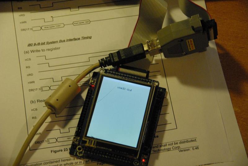
The least interesting and most costly (in terms of writing time) is the function of display initialization:
lcd_init: for those who want to get scared
u16 lcd_init(void) { RCC_APB2PeriphClockCmd(RCC_APB2Periph_GPIOB | RCC_APB2Periph_GPIOC, ENABLE); GPIO_InitTypeDef gpio_conf; gpio_conf.GPIO_Speed = GPIO_Speed_50MHz; gpio_conf.GPIO_Mode = GPIO_Mode_Out_PP; gpio_conf.GPIO_Pin = GPIO_Pin_8 | GPIO_Pin_9 | GPIO_Pin_10 | GPIO_Pin_11 | GPIO_Pin_12; GPIO_Init(GPIOC, &gpio_conf); lcd_gpio_conf(GPIO_Mode_Out_PP); // to init state (0xffff on db0-15, backlit is disabled, nCS, nWR, nRD and RS are high) _lcd_bl_dis(); _lcd_put_data(0xffff); _lcd_deselect(); _lcd_wr_dis(); _lcd_rd_dis(); _lcd_rs_set(); // osc enable _lcd_bl_dis(); lcd_write_reg(0x00, 0x0001); delay_ms(100); u16 lcd_code = lcd_read_reg(0x00); delay_ms(100); // driver output control (S720-S1) lcd_write_reg(0x01, 0x0100); // driving wave control (line inv) lcd_write_reg(0x02, 0x0700); // entry mode (horiz, dir(h+,v+), hwm-, bgr+) lcd_write_reg(0x03, 0x1030); // resize (off) lcd_write_reg(0x04, 0x0000); // display control 2 (skip 2 lines on front porch and on back porch) lcd_write_reg(0x08, 0x0202); // display control 3-4 (scan mode normal, fmark off) lcd_write_reg(0x09, 0x0000); lcd_write_reg(0x0a, 0x0000); // RGB disp iface control (int clock, sys int, 16bit) lcd_write_reg(0x0c, 0x0001); // frame marker position (isn't used) lcd_write_reg(0x0d, 0x0000); // RGB disp iface control 2 (all def, we don't use rgb) lcd_write_reg(0x0f, 0x0000); // power on seq lcd_write_reg(0x07, 0x0021); delay_ms(10); // turn on power supply and configure it (enable sources, set contrast, power supply on) lcd_write_reg(0x10, 0x16b0); // set normal voltage and max dcdc freq lcd_write_reg(0x11, 0x0007); // internal vcomh (see 0x29), pon, gray level (0x08) lcd_write_reg(0x12, 0x0118); // set vcom to 0.92 * vreg1out lcd_write_reg(0x13, 0x0b00); // vcomh = 0.69 * vreg1out lcd_write_reg(0x29, 0x0000); // set x and y range lcd_write_reg(0x50, 0); lcd_write_reg(0x51, LCD_WIDTH-1); lcd_write_reg(0x52, 0); lcd_write_reg(0x53, LCD_HEIGHT-1); // gate scan control (scan direction, display size) lcd_write_reg(0x60, 0x2700); lcd_write_reg(0x61, 0x0001); lcd_write_reg(0x6a, 0x0000); // partial displays off for(u8 addr = 0x80; addr < 0x86; addr++) { lcd_write_reg(addr, 0x0000); } // panel iface control (19 clock/line) lcd_write_reg(0x90, 0x0013); // lcd timings lcd_write_reg(0x92, 0x0000); lcd_write_reg(0x93, 0x0001); lcd_write_reg(0x95, 0x0110); lcd_write_reg(0x97, 0x0000); lcd_write_reg(0x98, 0x0000); lcd_write_reg(0x07, 0x0133); // turn on backlit after init done _lcd_bl_en(); return lcd_code; } Terminal implementation
This part is not particularly remarkable. Implemented unbuffered terminal, with part of the codes from previous articles.
escape sequences
Escape sequences:
Other useful codes:
- \ 033 [A = Move cursor one line up
- \ 033 [B = Move cursor one line down
- \ 033 [C = Move the cursor one position to the right
- \ 033 [D = Move the cursor one position to the left
- \ 033 [H = Move the cursor to the upper left corner - home (position 0,0)
- \ 033 [J = Clear all, does NOT return the cursor home!
- \ 033 [K = Erases to the end of the line, does NOT return the cursor home!
- \ 033 [M = New Character Map - Not Implemented
- \ 033 [Y = Position, accepts YX
- \ 033 [X = Position, takes XY
- \ 033 [R = CGRAM Memory selection is not implemented, since there is no CGRAM
- \ 033 [V = Scroll Enabled - Not Implemented
- \ 033 [W = Scrolling disabled - not implemented
- \ 033 [b = Backlight on / off - not implemented
Other useful codes:
- \ r = Carriage return (return the cursor to position 0 on the current line!)
- \ n = New line
- \ t = Tab (default 3 characters)
Communications
To interact with the outside world,
USART1 used in asynchronous mode via the PL-2303HX USB-to-UART PL-2303HX .From the point of view of the Linux host on board, this is
/dev/ttyUSBx . Unfortunately, the drivers for pl2303 were rather unstable. But, as soon as picked up, work well.In order not to poll the UART in the main loop (which is empty), work with it is implemented on interrupts.
From a software point of view, this means that after initializing USART1, you must configure the corresponding interrupt vector in NVIC .
It looks like this:
NVIC_InitTypeDef nvic_conf; nvic_conf.NVIC_IRQChannel = USART1_IRQn; nvic_conf.NVIC_IRQChannelPreemptionPriority = 0; nvic_conf.NVIC_IRQChannelSubPriority = 2; nvic_conf.NVIC_IRQChannelCmd = ENABLE; NVIC_Init(&nvic_conf); USART_ITConfig(USART1, USART_IT_RXNE, ENABLE); The last command allows the event to fill the receiving register USART1.
Accordingly, the processing looks like this:
void USART1_IRQHandler(void) { u8 data = USART1->DR; uart_write_byte(data); handle_byte(data); } We send the byte back (echo) and call the handler, which is a simple state machine.
handle_byte (u8)
// escape sequence handling vars u8 escape_seq = 0; u8 buf[10]; void handle_byte(u8 data) { if((!escape_seq) && (data == 0x1b)) { escape_seq = 1; } else if (escape_seq == 1) { buf[escape_seq] = data; escape_seq++; if(data != '[') { escape_seq = 0; } } else if (escape_seq == 2) { switch(data) { case 'A': lcd_term_set_cursor(lcd_term_row()-1, lcd_term_col()); break; case 'B': lcd_term_set_cursor(lcd_term_row()+1, lcd_term_col()); break; case 'C': lcd_term_set_cursor(lcd_term_row(), lcd_term_col()+1); break; case 'D': lcd_term_set_cursor(lcd_term_row(), lcd_term_col()-1); break; case 'H': lcd_term_set_cursor(0, 0); break; case 'J': lcd_term_clear(); break; case 'K': lcd_term_flush_str(); break; case 'X': case 'Y': buf[escape_seq] = data; escape_seq++; return; } escape_seq = 0; } else if(escape_seq == 3) { buf[escape_seq] = data; escape_seq++; } else if(escape_seq == 4) { u8 row = (buf[2] == 'Y') ? buf[3] - 037 : data - 037; u8 col = (buf[2] == 'Y') ? data - 037 : buf[3] - 037; lcd_term_set_cursor(row, col); escape_seq = 0; } else { lcd_term_put_str(&data, 1); } } All code is published in the github repository.
PS
Writing this post took almost 6 hours. Writing and debugging of the hardware-software part is about 13 hours.
Thanks to everyone who read it. About any ochepyatkah and other insects, write in a personal.
Source: https://habr.com/ru/post/207136/
All Articles