TCP / IP stack organization for MK based on the embedded module Tibbo
In this review article we will talk about the organization of the TCP / IP stack in your project based on the embedded modules from Tibbo Technology.

')
In most cases, developers work with their MK via the serial port. This is not always convenient. Often there is the task of "communicate" with the device remotely via the TCP / IP stack. The problem is not raised for the first time. For example, here this problem is voiced and solved with a fairly detailed description. In the link there is even a photo and a brief mention of the Tibbo EM100 module. The fact is that our company is the official representative of Tibbo Technology in the Russian Federation. Therefore, it is a little sad that they mentioned our product casually, without revealing the full functionality and capabilities of the product. I know very well this orange box called EM100, which has been produced for more than 10 years and which has been used in many facilities of our vast expanses. But much water has flowed since the release of this module. Let's try to create a TCP / IP stack for the device based on the Tibbo module, in parallel having considered the capabilities of the product.
To solve this problem, we need:
Embedded Modules (EM) are small intelligent modules that have their own microprocessor, the minimum necessary strapping for a quick start, various embedded protocols. As a rule, EM has its own operating system, which is not designed to communicate with a person. The purpose of using EM is to organize this or that functionality in the device as soon as possible and at minimal cost.
The family of Embedded modules from Tibbo Technology is quite powerful modules that already implement the physical layer of the 10/100 BaseT interface, organize full-fledged work with the TCP / IP protocol stack, and have from 1 to 4 serial UART ports at the CMOS level (TTL compatible) . On sale there are modifications of modules with integrated Ethernet connector and without it. To connect the latter, external connectors and transformers or a connector with integrated transformers are required. Module sizes vary, but in general they do not exceed (or slightly exceed) the RJ45 connector.
I chose the model EM1206 + RJ203, brief specifications:
For full-fledged and high-quality work with the module, it is necessary to foresee on the board: supply of stabilized power supply (3.3V), reset chip (desirable), if the Ethernet socket is not implemented, unsolder the corresponding connector.
Serial port, you need to connect to the controller of your device. As I wrote above, the CM1 level (TTL compatible) is implemented on the EM1206 module, so the Rx / Tx lines can be connected to the legs of the MK directly.

In the software part is still easier. Launch the Device Explorer, which automatically detects the module on the network (by sending UDP broadcast requests), uploading the firmware. The process takes no more than 1 minute.
Run DS Manager, which allows you to set parameters for both the serial interface and host parameters:
Brief characteristics of the firmware Serial Over IP:
Now our device transparently forwards the data stream to the Ethernet network and back. You can install a virtual COM port driver on a remote machine.
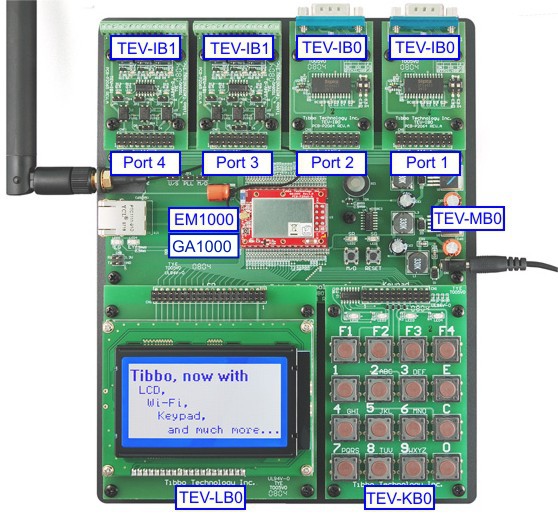
Optionally, when using the external GA1000 expansion module , Tibbo devices allow you to transfer data using the wireless data transfer protocol WiFi (802.11 b / g). GA1000 connects to the controller in an elementary manner; through the DS Manager utility, you can configure the connection settings to the access point.
In addition to the standard modes of operation in the local network, the embedded modules Tibbo implemented an object that allows you to automatically connect to the provider using PPPoE technology, which allows you to use the device as a client to connect to remote servers around the world.
Embedded modules Tibbo are freely programmable, and the process of debugging and downloading applications is carried out via Ethernet. Programming is carried out in object-oriented event languages Tibbo Basic and Tibbo C. For coding, the development environment from the manufacturer Tibbo IDE is used. The devices run the operating system TiOS , which processes the application written by the user and compiled into mnemonic codes in the interpretation mode. The modules have onboard general purpose input / output lines (GPIO), which allows using the embedded module as a microcontroller.
Most models have a web server that allows the user to program the web management interface. On some models, the RTC real-time clock is implemented.
Thus, the functionality of the module is determined only by the developer. If the SoI firmware is not enough, open the sources and add what you need. Or from scratch create your own project. For example, by implementing the protocol of your controller and hooking it to the OPC Server project (from Tibbo), the device can be connected to the SCADA system, and using the AggreGate Agent software library, you can connect the device to the AggreGate Server.
Let's consider a simple example: you need to compare the received parameter from the MC with a constant, and if the parameter exceeds the value, send a warning to the server. Elementary:
Initialize serial port:
Initialize the socket:
We will receive the data, compare it and send a critical event to the server:
As you can see, programming is not complicated at all.
If you do not want to mess with the wiring, you can use ready-made debugging boards, for example, EM500EV:
It is enough to connect the cable to the interface connector and you get the same functionality as with the embedded solution.
If your project does not require instant reactions, then Tibbo EM can be used as the main microcontroller of your device. Modules were created for the most convenient work with them. Free programming in high-level languages Tibbo Basic and Tibbo C will reduce the time to develop the firmware at times. As an example, you can consider creating your own access controller with a relay for controlling locks or connecting an external alarm system, a web server, serial ports, WiFi wireless connectivity, a keyboard and a display (schematic diagrams can be downloaded here ):
Serial ports can be used to connect RFID readers or magnetic cards. Relays are used to control the locks. Need to open the door? To do this, activate the relay. From the concept we see that the relay is “hanging” on the DTR0 (or GPIO5) line, we need to activate this line:
Finally, if you are interested in creating your own automation devices, look at the Tibbo TPS automation hardware platform overview .
Other examples of using Tibbo products can be found here .
PS
Our company provides a free testing service for the entire line of Tibbo equipment.
If you are interested in our products and you would like to purchase them, when ordering in our office, say the code word “Habrahabr” and you will receive a small pleasant discount. The promotion is valid until January 31, 2014.
')
In most cases, developers work with their MK via the serial port. This is not always convenient. Often there is the task of "communicate" with the device remotely via the TCP / IP stack. The problem is not raised for the first time. For example, here this problem is voiced and solved with a fairly detailed description. In the link there is even a photo and a brief mention of the Tibbo EM100 module. The fact is that our company is the official representative of Tibbo Technology in the Russian Federation. Therefore, it is a little sad that they mentioned our product casually, without revealing the full functionality and capabilities of the product. I know very well this orange box called EM100, which has been produced for more than 10 years and which has been used in many facilities of our vast expanses. But much water has flowed since the release of this module. Let's try to create a TCP / IP stack for the device based on the Tibbo module, in parallel having considered the capabilities of the product.
Creating a TCP / IP stack.
To solve this problem, we need:
- Embedded module Tibbo
- Free open source firmware Serial Over Ip
- Free Device Explorer utility (as part of TIDE)
- Free Tibbo Device Server ToolKit (TDST) Toolkit
Embedded Modules (EM) are small intelligent modules that have their own microprocessor, the minimum necessary strapping for a quick start, various embedded protocols. As a rule, EM has its own operating system, which is not designed to communicate with a person. The purpose of using EM is to organize this or that functionality in the device as soon as possible and at minimal cost.
The family of Embedded modules from Tibbo Technology is quite powerful modules that already implement the physical layer of the 10/100 BaseT interface, organize full-fledged work with the TCP / IP protocol stack, and have from 1 to 4 serial UART ports at the CMOS level (TTL compatible) . On sale there are modifications of modules with integrated Ethernet connector and without it. To connect the latter, external connectors and transformers or a connector with integrated transformers are required. Module sizes vary, but in general they do not exceed (or slightly exceed) the RJ45 connector.
I chose the model EM1206 + RJ203, brief specifications:
- Based on a high-performance 88MHz ASIC (T1000) controller.
- 100BaseT with integrated transformer decoupling (when using RJ203).
- Up to 1024KB flash-memory for firmware, applications and data.
- 2KB EEPROM for data storage.
- Real Time Clock (RTC) ..
- Up to 17 general-purpose I / O lines (including 8 interrupt lines).
- Control lines of two external status LEDs.
- 4 built-in LEDs:
- green and red status LEDs;
- green and yellow Ethernet status LEDs.
- Software controlled embedded PLL.
- Reliable power reset circuit.
- Power supply: 230mA @ 3.3V (100BaseT mode, PLL is on).
- Dimensions: 33.2x18.1x5.5mm.
For full-fledged and high-quality work with the module, it is necessary to foresee on the board: supply of stabilized power supply (3.3V), reset chip (desirable), if the Ethernet socket is not implemented, unsolder the corresponding connector.
Serial port, you need to connect to the controller of your device. As I wrote above, the CM1 level (TTL compatible) is implemented on the EM1206 module, so the Rx / Tx lines can be connected to the legs of the MK directly.
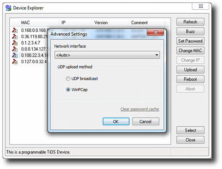
Convenient software for work
In the software part is still easier. Launch the Device Explorer, which automatically detects the module on the network (by sending UDP broadcast requests), uploading the firmware. The process takes no more than 1 minute.
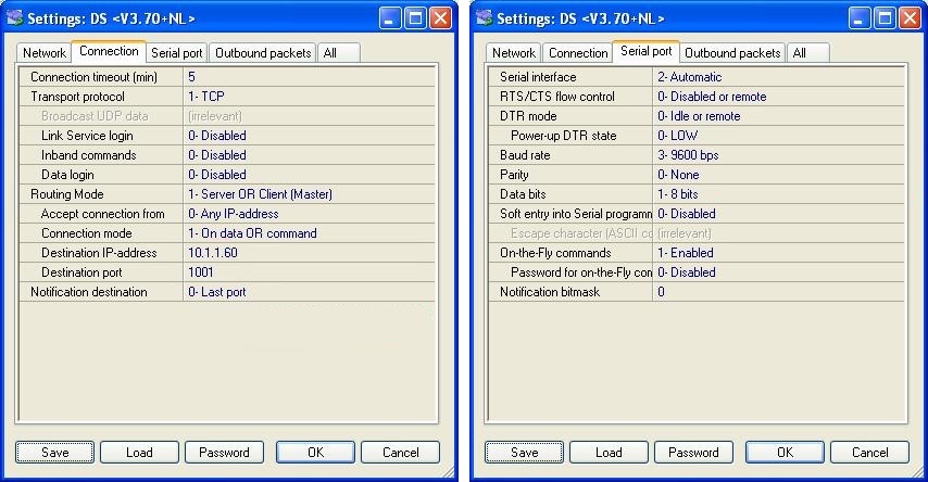
Run DS Manager, which allows you to set parameters for both the serial interface and host parameters:
Brief characteristics of the firmware Serial Over IP:
- Full and half duplex serial port modes.
- Available modes: server, client and server / client.
- Many other options for serial and ethernet connections.
- 8KB for each receive / transmit buffer (in each direction one buffer).
- The configuration is stored in the EEPROM.
- Detailed status indication via LEDs.
- Setup via RS232 or ethernet (UDP commands, Telnet).
- Remote control of all I / O lines (including RTS, CTS, DTR and DSR).
- "On-the-fly" commands for serial port configuration.
- "Modem" commands via RS232 to control the network connection.
- Direct control of the ADSL modem.
- Supports UDP, TCP, ARP, ICMP (ping), DHCP, PPPoE, LCP protocols.
- Built-in web management interface.
Now our device transparently forwards the data stream to the Ethernet network and back. You can install a virtual COM port driver on a remote machine.
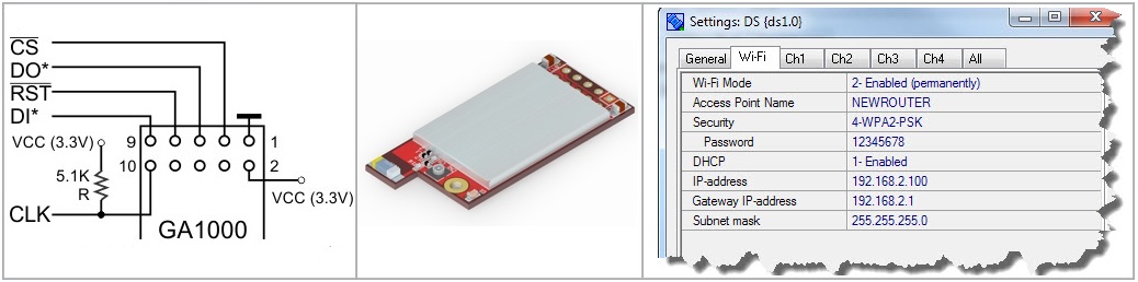
Optionally, when using the external GA1000 expansion module , Tibbo devices allow you to transfer data using the wireless data transfer protocol WiFi (802.11 b / g). GA1000 connects to the controller in an elementary manner; through the DS Manager utility, you can configure the connection settings to the access point.
In addition to the standard modes of operation in the local network, the embedded modules Tibbo implemented an object that allows you to automatically connect to the provider using PPPoE technology, which allows you to use the device as a client to connect to remote servers around the world.
And it's all? And where is the intellect, where is the logic?
Embedded modules Tibbo are freely programmable, and the process of debugging and downloading applications is carried out via Ethernet. Programming is carried out in object-oriented event languages Tibbo Basic and Tibbo C. For coding, the development environment from the manufacturer Tibbo IDE is used. The devices run the operating system TiOS , which processes the application written by the user and compiled into mnemonic codes in the interpretation mode. The modules have onboard general purpose input / output lines (GPIO), which allows using the embedded module as a microcontroller.
Most models have a web server that allows the user to program the web management interface. On some models, the RTC real-time clock is implemented.
Thus, the functionality of the module is determined only by the developer. If the SoI firmware is not enough, open the sources and add what you need. Or from scratch create your own project. For example, by implementing the protocol of your controller and hooking it to the OPC Server project (from Tibbo), the device can be connected to the SCADA system, and using the AggreGate Agent software library, you can connect the device to the AggreGate Server.
Let's consider a simple example: you need to compare the received parameter from the MC with a constant, and if the parameter exceeds the value, send a warning to the server. Elementary:
Initialize serial port:
sub on_sys_init ser.num=0 ' ser.rxbuffrq(4) ' 4*256-16=1008 ser.txbuffrq(4) ' 4*256-16=1008 ..... sys.buffalloc ' . ser.num=0 ser.flowcontrol=DISABLED ' ser.baudrate=12 'ser.div9600/(38400/9600) 38400 ser.enabled=YES ' ....... end sub Initialize the socket:
sub on_sys_init ..... sock.num=0 sock.rxbuffrq(4) sock.txbuffrq(4) ..... sys.buffalloc sock.num=0 sock.protocol=PL_SOCK_PROTOCOL_TCP sock.localportlist="2000,3000" sock.inconmode=PL_SOCK_INCONMODE_ANY_IP_ANY_PORT sock.targetip="192.168.1.100" sock.targetport="1001" end sub We will receive the data, compare it and send a critical event to the server:
sub on_ser_data_arrival '. . dim s as string s = ser.getdata(ser.rxlen) If val(s) > Critical_value then sock.num = 0 sock.connect sock.setdata("! : "+s) sock.send end if end sub As you can see, programming is not complicated at all.
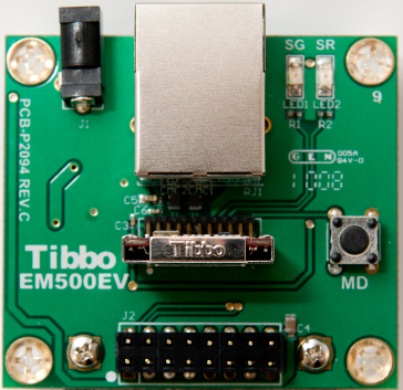
If you do not want to mess with the wiring, you can use ready-made debugging boards, for example, EM500EV:
It is enough to connect the cable to the interface connector and you get the same functionality as with the embedded solution.
Replacing the MK with a Tibbo embedded module.
If your project does not require instant reactions, then Tibbo EM can be used as the main microcontroller of your device. Modules were created for the most convenient work with them. Free programming in high-level languages Tibbo Basic and Tibbo C will reduce the time to develop the firmware at times. As an example, you can consider creating your own access controller with a relay for controlling locks or connecting an external alarm system, a web server, serial ports, WiFi wireless connectivity, a keyboard and a display (schematic diagrams can be downloaded here ):
Serial ports can be used to connect RFID readers or magnetic cards. Relays are used to control the locks. Need to open the door? To do this, activate the relay. From the concept we see that the relay is “hanging” on the DTR0 (or GPIO5) line, we need to activate this line:
.... io.num = PL_IO_NUM_5 io.enabled = YES io.state = LOW .... Finally, if you are interested in creating your own automation devices, look at the Tibbo TPS automation hardware platform overview .
Other examples of using Tibbo products can be found here .
PS
Our company provides a free testing service for the entire line of Tibbo equipment.
If you are interested in our products and you would like to purchase them, when ordering in our office, say the code word “Habrahabr” and you will receive a small pleasant discount. The promotion is valid until January 31, 2014.
Source: https://habr.com/ru/post/206920/
All Articles