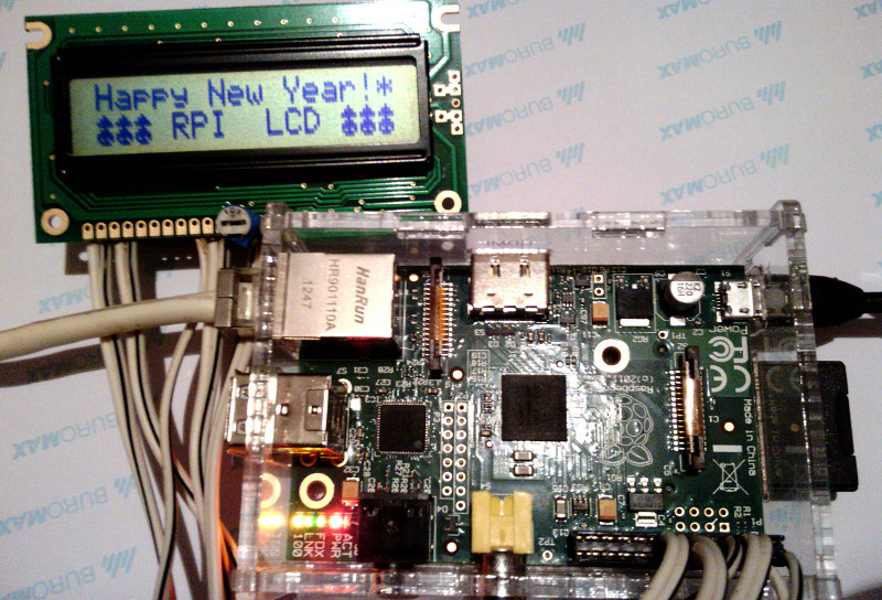
Christmas Raspberry - Screw the HD44780 to Raspberry Pi
Holiday greetings!
Infused with post ideas: “Congratulations on geeks, without writing firewood” and “Creating your own drivers for Linux” decided to share another screen control method based on the HD44780 controller with the help of Raspberry Pi.
Bcm2835 library
The main task of the LPT port, demos, and other cool things, when controlling the screen, is to pull the screen with the right legs according to the data received from the computer.
In my case, there is no division into a computer and control board, as the RPI has an excellent General-purpose input / output (GPIO) interface that can be controlled directly from the program. For this, I decided to use the bcm2835 library.
Screen connection
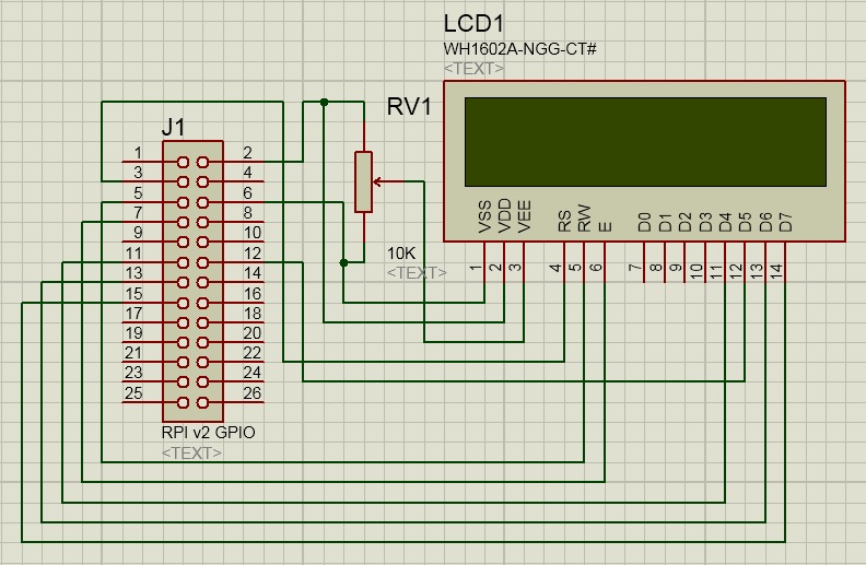
There should be nothing complicated. Obratat attention that I have a raspberry second revision and pinout connector is slightly different from the first.
You can see pinout for both versions here .
')
Management program
For convenient work with the screen I have written a simple library of the most important in my opinion functions of working with the screen. The library is quite raw and incomplete, but suitable for the current task.
First you need to adjust it a bit:
file HD44780.h
#define HD44780_DB4 RPI_V2_GPIO_P1_11 #define HD44780_DB5 RPI_V2_GPIO_P1_12 #define HD44780_DB6 RPI_V2_GPIO_P1_13 #define HD44780_DB7 RPI_V2_GPIO_P1_15 #define HD44780_RS RPI_V2_GPIO_P1_03 #define HD44780_RW RPI_V2_GPIO_P1_05 #define HD44780_E RPI_V2_GPIO_P1_07 Here it is required to indicate the correspondence of the GPIO and LCD contacts, if the connection scheme does not differ from the above one does not need to change anything.
You might also need to fix lcd.c:
#define MAX_DISP_ROWS 2 // The HD44780 supports up to 4 rows #define MAX_DISP_COLS 16 // The HD44780 supports up to 40 columns Required to specify the size of your screen.
Important: the screen is powered by a voltage of 5 volts, and the raspberry works with logic levels of 3.3V, the screen understands these levels perfectly, but the raspberry, if the screen tries to transmit something to it, can not withstand because “GPIO voltage levels are 3.3 V and are not 5 V tolerant. There is no over-voltage protection on the board ” from here . Therefore, reading anything from the screen is strongly discouraged. For everything to work on the mind you need a level converter, and not a direct connection.
Working with the program is not too different from working with the port from the goodic article, all the same control sequences are here as I was based on the code from his project which is based on the project from dlinyj who used the code written by Michael McLellan . OpenSource taxis. :)
sequences
So, control sequences for our screen:
- \ 033 = Sending an ESC sequence from which commands begin.
- [A = Move cursor one line up
- [B = Move cursor one line down
- [C = Move the cursor one position to the right.
- [D = Move the cursor one position to the left
- [H = Move the cursor to the upper left corner - home (position 0.0)
- [J = Clear all, does NOT return the cursor home!
- [K = Erases to the end of the line, does NOT return the cursor home!
- [M = New Character Map (DZ - explain why!)
- [Y = Position Y (see FAQ below)
- [X = Position X (see FAQ below)
- [R = CGRAM memory selection
- [V = Scroll Enabled
- [W = Scrolling off
- [b = Backlight on / off (will not work with us).
Other useful commands work without the \ 033 prefix!
- \ r = Carriage return (return the cursor to position 0 on the current line!)
- \ n = New line
- \ t = Tab (default 3 characters)
The only change: added the sequence [i responsible for the initial initialization of the display.
It needs to be transmitted when you first access the screen.
For example:
Initialize the screen.
root@raspberrypi:/home/pi/lcd# echo -en "\033[i" | ./lcd Print the text.
root@raspberrypi:/home/pi/lcd# echo -en "\033[R0\004\016\037\004\016\037\025\016\033[J\033[HHappy New Year\041*\r\n\000\000\000 RPI LCD \000\000\000" | ./lcd 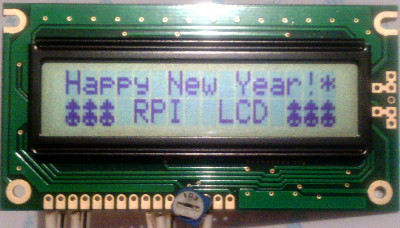
From the minuses of this solution, you can notice the need to run the program from under administrator rights, this can be solved by writing a driver, but I figured out how to steer a raspberry from the kernel I did not get.
Sources
Assembly:
root@raspberrypi:/home/pi/lcd$ gcc -o lcd lcd.c HD44780.c -lrt -lbcm2835 In order not to lose, I post it in the form of zipjpeg:
UPD: sources
UPD2: figured out with the driver , device / dev / gpiolcd, the rest is the same as here
UPD3: Github
Happy New Year!
Source: https://habr.com/ru/post/206782/
All Articles