From smart home to smart corporations
“... If at that moment Mr. Ripley led us into the courtyard and, turning to the house, said:“ Become a house, back to New York, and come to me ”, and the house, like a hut on chicken legs, would fulfill this a request with the help of electricity, we would not be too surprised. "
Ilf and Petrov. One-story America. 1935
Part one
Introduction

')
We are a company that celebrated 5 years this year, an SAP partner with an APCS last. At the moment, we are implementing property management systems for large companies, property owners. For reference: often the number of objects is several tens of thousands (rarely hundreds of thousands), and the area exceeds millions of square meters. For such companies, with their geography and requirements for reliability and security, SAP is the preferred solution, but this article is not about this (we can tell about this if you are interested).
This article is not about this, but about the fact that we had a chance to start building a high-tech and intelligent country private cottage ... and we gladly took it. And we offer you the history of the path that we have taken since the beginning of the year, from a smart cottage to a smart corporation.
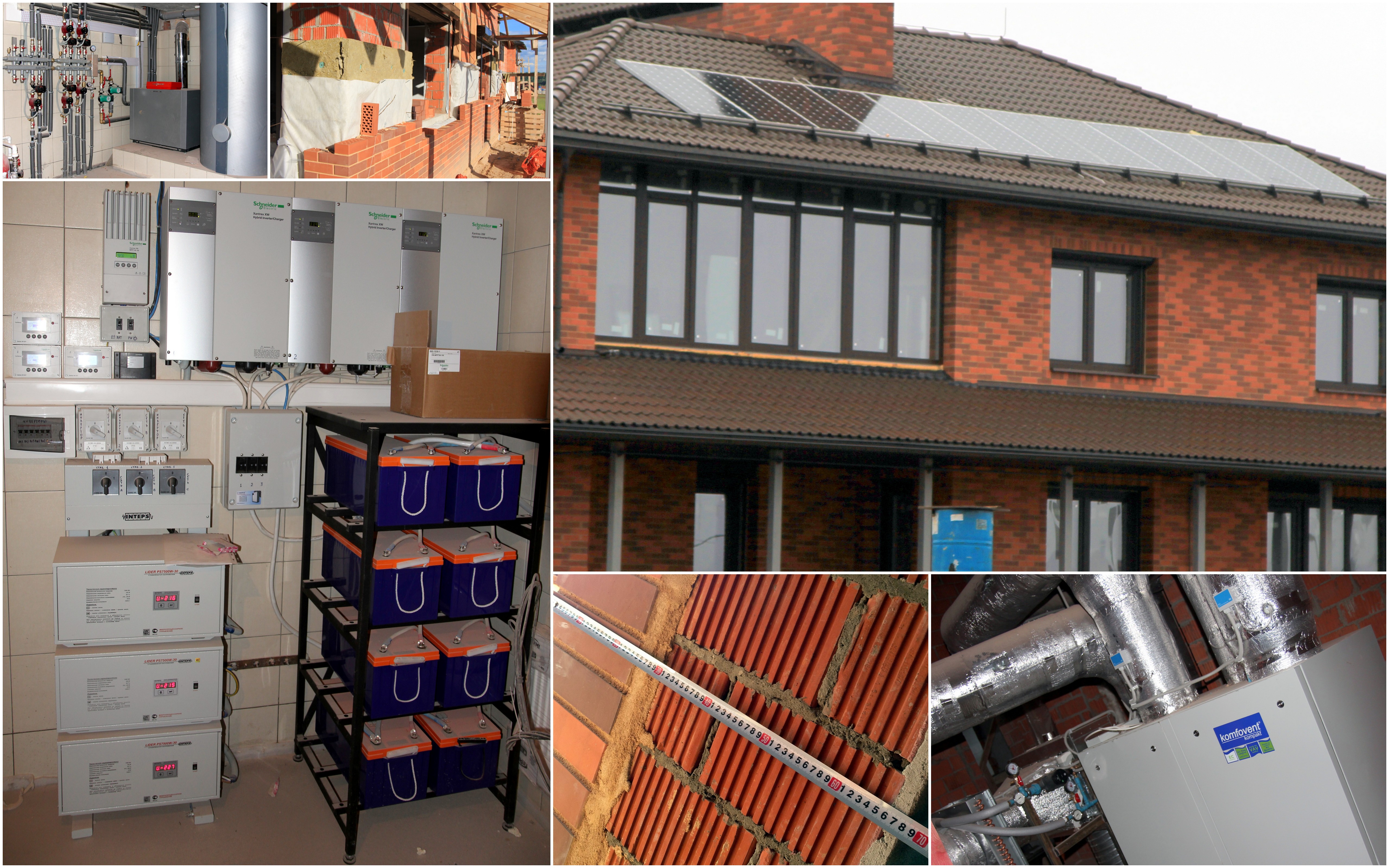
At all stages of construction and engineering solutions we will not stop, I would like to mention only the distinctive characteristics in terms of autonomy and energy efficiency:
- The walls are made of ceramic stone, insulated with a 15 cm thick layer of mineral insulation, and this brick is completed with this cake. Taking into account the finishing, the wall thickness is about 70 centimeters, which should ensure good heat preservation in the conditions of the Moscow region winter.
- Window. Six-chamber frames with energy-efficient glass panes were used (the main source of heat loss - the IR spectrum is 98% reflected back). Electric windows and shutters are installed above the windows that protect against vandalism, they create an additional air layer, and shade the sunny side in summer.
- Energy. At the forefront is the Schneider Electric Xantrex system, as well as an input stabilizer, a battery pack, a 3.6 kW solar panel, an automatic generator start and control via a web interface.
- Heating. Multi-loop boiler, gas boiler, solar power plant and heat pump. Heated floors and radiators in the rooms have individual lines with electric valves (climate control in each room).
- Ventilation. Forced-air and exhaust installation with a recuperator and hydraulic system (we warm in winter, cool in summer). In each room / zone individual ventilation valve. The unit has a differential pressure sensor and automatic performance adjustment.
- Lighting. Mostly LED. Second light using SolarTube.
Here we have such an object for automation. We were faced with the task of linking all engineering systems at home into a single, simple and understandable control system that would ensure comfortable, safe and energy-efficient living. Everyone remembers Alice ( http://habrahabr.ru/post/160067/ ), and we, being impressed by this and some other projects, decided to repeat something similar. We also wanted the system to be truly intelligent. With minimal controls.
For example:
- The light turns on automatically depending on the time of day, outside lighting, the selected scenario and the presence of a person in the room (it is for detecting presence, not movement (!!!), we have a special sensor from Leviton).
- The ventilation level in a single room is automatically controlled by the presence of a person in it and the CO2 content in the air ( http://habrahabr.ru/post/187210/ ). Unlike the existing standards with the triple exchange of air in the room.
- For the maintenance of the temperature in the room meet the radiator batteries, heated floors, ventilation system.
And, of course, in each room I wanted to give my voice commands (not Google); switch scenarios (cinema, sleep, disco); manage multimedia, roll shutters, sockets; set / disarm; be able to remotely control from a phone / tablet, including connecting to IP cameras. At some point we approached the design of architecture, and we faced a choice: either to do everything on KNX, or to invent something of our own. As you have probably guessed, we chose the second option. A large number of ready-made devices / interfaces, beautiful frames and switches spoke for KNX, but the only thing that was not in favor of KNX was two knowledge: knowledge of how much electronic components cost and knowledge of how to do it all by yourself. So we approached the creation of our controller. When we were thinking about how it should be, we thought that it would be great to make such a platform that we could use, both at home and in most of our commercial projects.
We had the idea of creating the most simple and compact product that could be installed in any apartment for little money. In addition, the system must be modular and flexibly adapt to different tasks. At the same time, it can be used both in the housing and utilities sector (public sector) and in the corporate segment.
At first, we tried to formulate the criteria that the controller of the “SMART HOME” should meet:
- The controller should be based on the principles of "Open software and hardware" (Open-source software, Open-source hardware). The programming environment should be simple and straightforward. Anyone with technical knowledge could independently create / upgrade and program such a device.
- The controller should be universal and used in all aspects of the management of "SMART HOME" from the warm floor to multimedia. Compatible with various types of sensors, actuators, ready-made solutions for ventilation, heating and security.
- The controller must be self-sufficient and “autonomous” for use in one single room, but several controllers must be networked and in this case, the scope is expanded to an apartment, a cottage or a large building controlled by a central server.
- The controller must support data transmission over Ethernet or Wi-Fi (optional).
- The controller must be compact in size to fit in a standard socket, and leave enough space for the associated wiring.
- The controller must have low cost and high reliability.
System development
As a basis for the entire system, our choice fell on the controller platform “Arduino”
There is a lot of information on projects, user cases implemented on this platform on the Internet, so we will not dwell separately on it, we only note that it fully complies with the above criteria.
As a prototype, it was decided to combine the most compact versions of the controller and the network module, making a multilayer board. Controller board - Femtoduino with ATMEGA328p-MU on board, network module based on ENC26J60, a pair of stabilizers, resistors, terminal blocks.
We placed all this on a small printed “motherboard”. At the same time, the controller board is placed entirely in the standard plug, and the largest structural element is the RJ45 connector for the network cable.
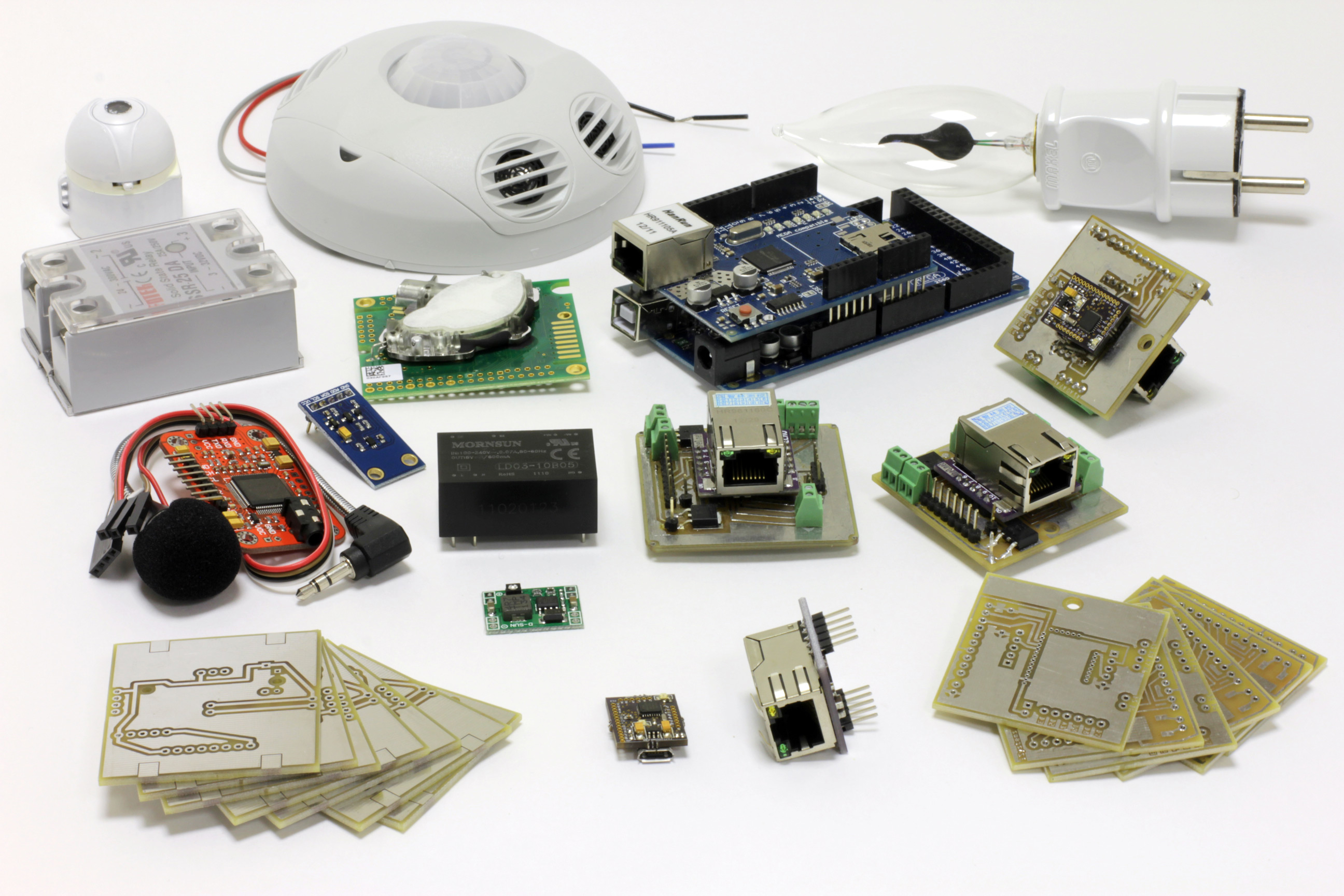
In the photo: WiFi camera, Leviton presence sensor, 220V candle light, solid-state relay, CO2 sensor K-30, Arduino Mega2560 + Ethernet Shield, our controller v1 and v2, voice recognition module, AC-DC 5V (600ma), femtoduino usb, dc-dc converter, enc26j60
Initially, for the prototype, it was planned to make the necessary printed circuit boards using the LUT method, but the pitch between the pins for connecting the controller was too small, which increased the quality requirements of the board. After a couple of unsuccessful attempts, LUT had to be abandoned and ordered a fee from a specialized organization.
Femtoduino
There are two versions of this controller: with a miniUSB connector for programming and without.
The first controller versions that came to us were without a connector and were programmed via another Arduino-compatible controller using AVRIsp. For the convenience of programming on the motherboard was provided a male connector for a cable connected to the board by the programmer. However, this programming method is far from the most convenient. In addition, in the process of work, several controllers of this type had failed due to errors during rewriting. In the new version of this problem was no longer.
Femtoduino usb
The second version of the controller has greatly simplified working with it, since a special USB connector is now provided for programming. It is programmed like any other Arduino board. However, due to the FTDI chip, which is needed for its operation, there was a problem with the connection of the controller with the voice recognition module. The Rx / Tx outputs completely refused to work with anything other than USB. The problem was never resolved (the board developer acknowledged that FTDI really interferes with the work of the necessary conclusions), so I had to use a workaround — the SoftwareSerial library. It allows you to emulate a serial port on any pins, instead of hardware, which refused to work.
ENC26J60
This is a very compact network module, actually consisting of only one RJ45 connector on a miniature board of almost the same size. Unfortunately, the library of the standard Arduin's Ethernet module is not suitable for this ENC26J60; instead, the EtherCard library was used. This library is quite different from the built-in development environment, which is not very convenient when developing sketches for it.
Thus, all the necessary devices were tested and assembled on the motherboard. The result is the following controller:
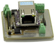
During the transition to Femtoduino USB, the controller was able to be reduced in size:

As a result, we have a compact controller that connects to the server via an Ethernet cable and is capable of solving broad home automation tasks (powered by 220V as an option in the photo).
TTH:
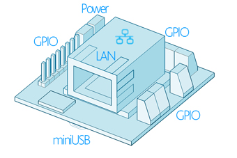
- Dimensions: 45x43x25 mm
- Micro-B USB port for programming
- RJ45 for network connection
- DC power
- 5-10V (100-240VAC - option)
- Microcontroller: ATMEGA328p-MU
- Program Memory Size: 32 KB
- Data RAM Size: 1 KB
- Available: 8 analog ports, 11 digital ports
- I2C: A4 (SDA) and A5 (SCL) ports
- PWM: ports A3, D5, D6 and D9
Scope of the Smart Home Solution
Comfort
- air quality control
- climate control (integration with ventilation / air conditioning / heating)
- rolling shutters / blinds / garage doors
- control of warm floors (water / electric)
- light control (additional components are required for dimming)
- voice control
- automatic scripts
- irrigation management
Security
- Access control to the object (arming / disarming)
- Motion / Presence Detection
- Fire safety
- Control of opening / closing windows / doors
- Water leakage detection
- Integration with video surveillance system
- Notification via various SMS / Email channels
Efficiency
Automatic monitoring of metering devices
- water
- gas
- electricity
Server side development
For the server part of the system, our choice fell on the MajorDoMo project. MajorDoMo is an open and accessible platform for automating and managing your smart home system. Details about the project can be found on the developer site smartliving.ru. This software product fully meets the requirements for our system. It is an open, easy-to-configure system that can be adapted for a wide variety of automation tasks. At the same time, the system is controlled via a web interface, which allows using it from any devices.
MajorDoMo uses the PHP language to program all the scenarios of the system, while it provides a user-friendly graphical interface that allows even people who are not familiar with programming to understand the system setup.
In our project, we planned to use the MajorDoMo package installed on the Raspberry Pi, which can be used as a web server. During the tests, it became clear that MajorDoMo is too demanding on the hardware, and such a weak server hardly copes with the task. After attempts to optimize the server part and overclocking the piece of hardware itself, it was decided to abandon it, since the delay between sending and executing commands was too great. Later, as a server for MajorDoMo, we used a dedicated server (Digital Ocean), to which we connected via a 3G modem. Despite the fact that the server is located in Amsterdam, the response to the execution of commands has become almost instant.
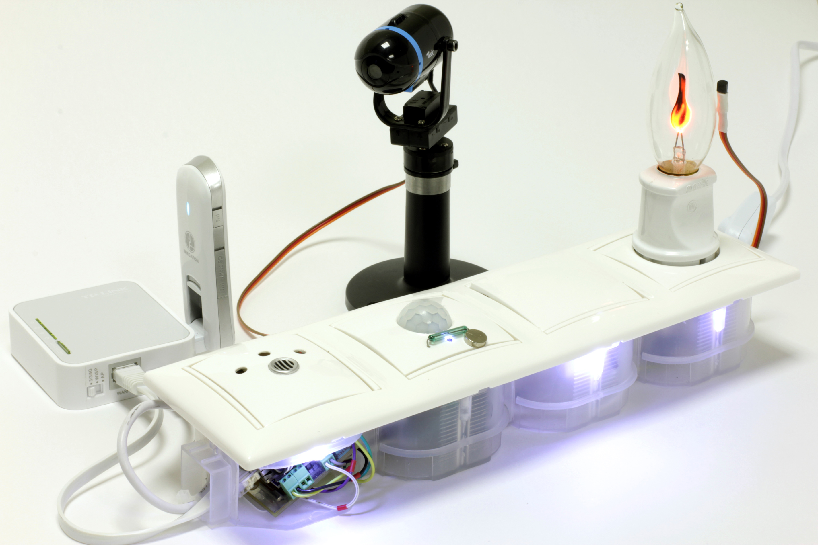
Based on the last prototype, it was decided to make a demonstration stand, which would allow to visually show all the functionality of the received controller of the smart home system.
TP-Link 3020 came to the place of Raspberry Pi with custom firmware, which was connected to a dedicated server, and the whole system was accessible via an external IP.

It was decided to place a separate board with sensors in the front false panel covering the front panel. There are two light sensors on this board: a digital one that can recalculate the result in suites, and a conventional photoresistor, as well as a digital temperature sensor (DS18B20, which is without it), a voice recognition module panel and a microphone for it. To connect the board with the sensor, a separate loop is made, which is connected directly to the controller board in the connector reserved for it. The sensor board turned out to be so compact that it practically does not take place inside the box itself. The entire filling fit in the space between the underframe frame and the lid.
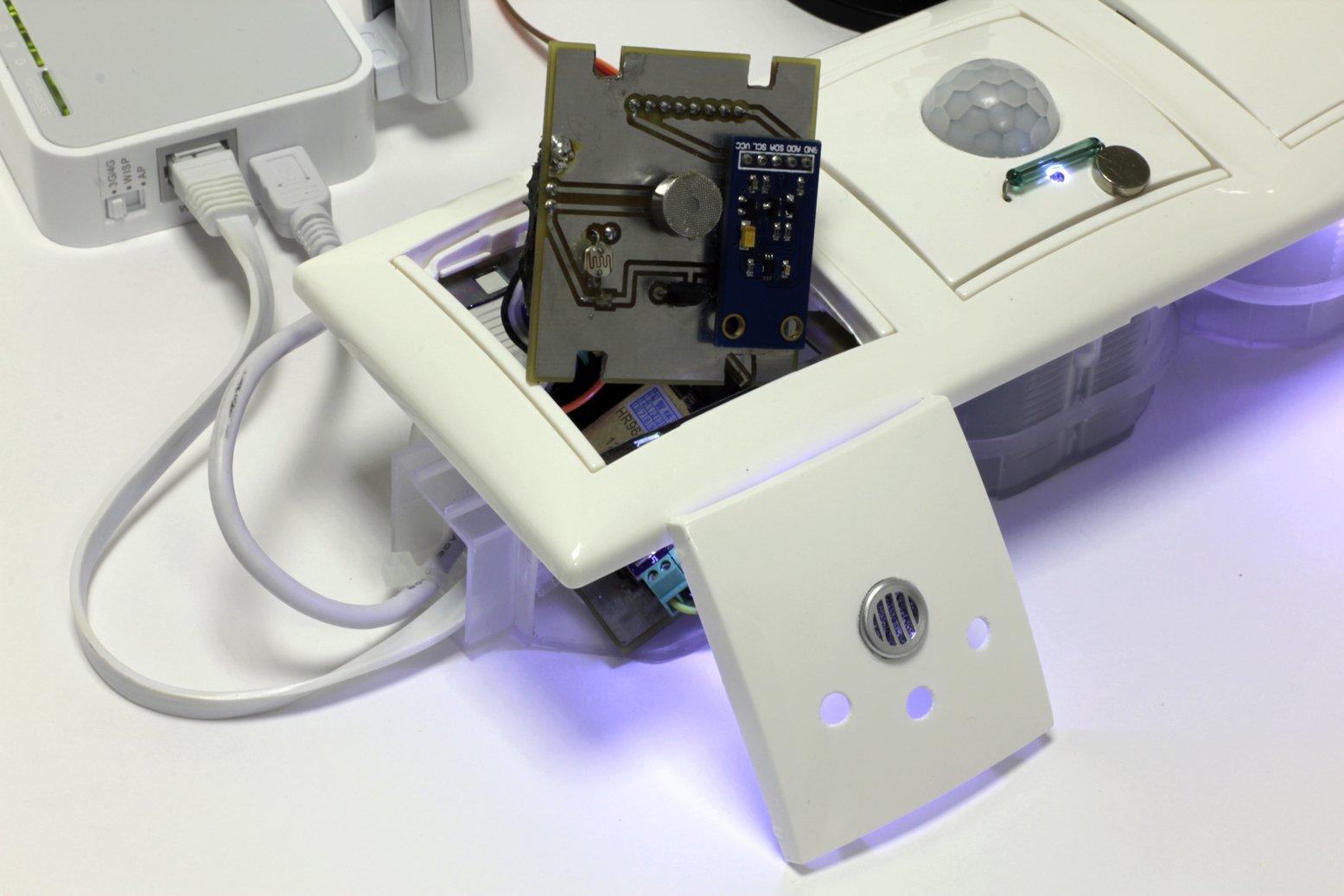
Final layout architecture:
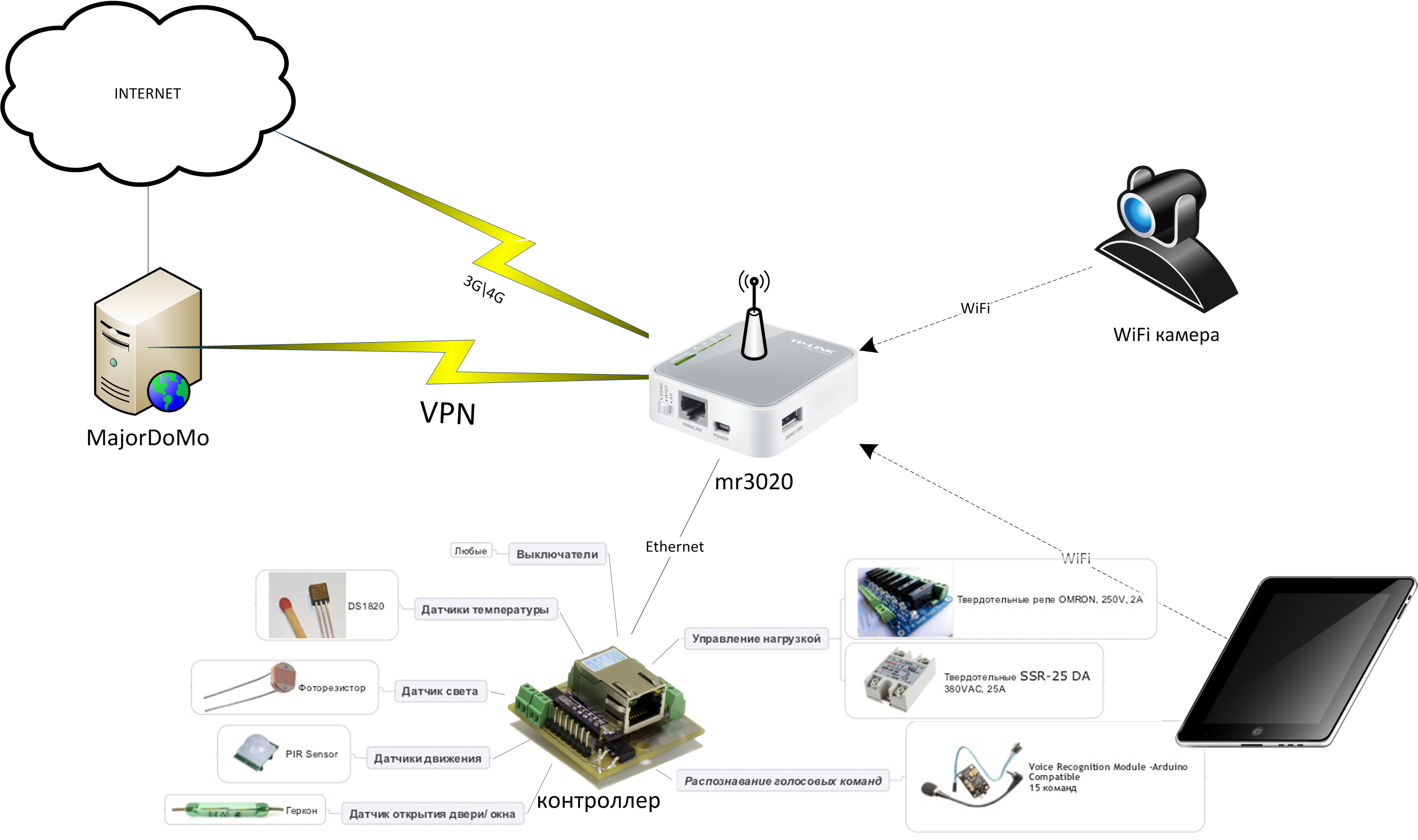
The stand itself in the final form consists of four podzetnika, fastened together. Two of them are a controlled socket (socket + solid-state relay) and a push-button switch connected to the controller. Using a relay, you can control the load connected to this outlet, for example, a light bulb. In the third podrozetnik located power supply for the entire system, and in the fourth controller itself.
In addition to the panel with sensors installed on the controller (which includes a temperature sensor, two light sensors and a microphone), two additional temperature sensors (1-Wire), a reed switch, a motion sensor and LEDs are connected to the controller. Also on the layout is a connector for connecting a WiFi camera with a servo drive.
As you can see, we got a fairly voluminous binding for such a miniature controller. In addition, many of the sensors used are digital, which means they require the use of libraries to work with them. Because of this, there was a problem when writing a sketch for the layout. The controller of this type is not so much memory, which puts a limit on the size of the program code. The problem was solved by a significant code optimization.
The full code can be found here.
(more info)
#include <EtherCard.h> #include <Servo.h> #include <OneWire.h> #include <DallasTemperature.h> #include <SoftwareSerial.h> SoftwareSerial mySerial(1, 0); //Software serial initialization #define ONE_WIRE_BUS 4 //Dallas initialisation OneWire oneWire(ONE_WIRE_BUS); DallasTemperature sensors(&oneWire); DeviceAddress Ter1; DeviceAddress Ter2; DeviceAddress Ter3; int tempC1 = 1; int tempC2 = 1; int tempC3 = 1; static byte mymac[] = { 0x74,0x69,0x69,0x2D,0x30,0x31 }; static byte myip[] = { 192,168,0,150 }; static byte gwip[] = { 192,168,0,1 }; static byte hisip[] = { 192,168,2,1 }; //char website[] PROGMEM = "192.168.2.1"; #define REQUEST_RATE 3000 Servo servo1; int xAxis = 90; int BH1750address = 0x23; byte buff[2]; int dLight = 0; #define relay1Pin 9 // //#define relay2Pin 2 // #define buttonPin 3 // int buttonState = HIGH; int lastButtonState = LOW; long lastDebounceTime = 0; long debounceDelay = 100; int lightState = 0; #define reedPin 8 int reedState = 0; #define PIRPin 7 int pirState = 0; #define photo1Pin = 2; int photo1Value = 0; int sensor = 0; // #define LED1Pin 2 #define LED2Pin 5 #define LED3Pin A0 #define LED4Pin A1 int background = 0; const char http_OK[] PROGMEM = "HTTP/1.0 200 OK\r\n" "Content-Type: text/html\r\n" "Pragma: no-cache\r\n\r\n"; const char link[] PROGMEM = "GET /objects/?object="; const char linkLight[] PROGMEM = "GET /objects/?object=lightgroup1&op=m&m=updateState&state="; const char website[] PROGMEM = " HTTP/1.1" "\r\n" "Host: 192.168.2.1" "\r\n" "\r\n"; byte Ethernet::buffer[600]; BufferFiller bfill; Stash stash; static long timer; ///////////////////////////////////////// SETUP ///////////////////////////////////////// void setup () { mySerial.begin(9600); sensors.begin(); sensors.getAddress(Ter1, 0); sensors.setResolution(Ter1, 12); sensors.getAddress(Ter2, 1); sensors.setResolution(Ter2, 12); sensors.getAddress(Ter3, 2); sensors.setResolution(Ter3, 12); ether.begin(sizeof Ethernet::buffer, mymac, 10); ether.staticSetup(myip, gwip); ether.copyIp(ether.hisip, hisip); timer = - REQUEST_RATE; // servo1.attach(6); pinMode(relay1Pin, OUTPUT); pinMode(buttonPin, INPUT); pinMode(reedPin, INPUT); pinMode(PIRPin, INPUT); pinMode(LED1Pin, OUTPUT); pinMode(LED2Pin, OUTPUT); pinMode(LED3Pin, OUTPUT); pinMode(LED4Pin, OUTPUT); delay (100); // mySerial.write(0xAA); mySerial.write(0x37); delay(100); mySerial.write(0xAA); mySerial.write(0x21); delay(100); } ///////////////////////////////////////// LOOP ///////////////////////////////////////// void loop () { word len = ether.packetReceive(); word pos = ether.packetLoop(len); netSend(); if (pos) netReply(pos); checkButton(); checkReed(); checkPIR(); checkSerial(); } //////////////////////////////////////// NETWORK //////////////////////////////////////// void netSend() { // if (millis() > timer + REQUEST_RATE) { timer = millis(); switch (sensor) { case 0: // sensor = 1; photo1Value = analogRead(2); Stash::prepare(PSTR("$Fphoto1&op=m&m=updateValue&value=$D$F"), link, photo1Value, website); ether.tcpSend(); break; case 1: // sensor = 2; //dLight = getLx(); //Stash::prepare(PSTR("$Fdlight1&op=m&m=updateValue&value=$D$F"), link, dLight, website); //ether.tcpSend(); break; case 2: // sensor = 0; sensors.requestTemperatures(); tempC1 = (int)(sensors.getTempC(Ter1)*100); tempC2 = (int)(sensors.getTempC(Ter2)*100); tempC3 = (int)(sensors.getTempC(Ter3)*100); Stash::prepare(PSTR("$Fds1&op=m&m=updateTemp&temp=$D&temp2=$D&temp3=$D$F"), link, tempC1, tempC2, tempC3, website); ether.tcpSend(); break; } } } void netReply(word pos) { // bfill = ether.tcpOffset(); char *data = (char *) Ethernet::buffer + pos; char sub[4]; char *var; var = strstr(data, "srv1="); if (var != NULL) { var += 5; for (int i=0; i<=2; i++) sub[i] = var[i]; xAxis = atoi(sub); servo1.write(xAxis); } var = strstr(data, "lgr1="); if (var != NULL) { Serial.print("Command recieved!"); digitalWrite(52, 1); } //LED Control var = strstr(data, "led1="); if (var != NULL) { var += 5; for (int i=0; i<=1; i++) sub[i] = var[i]; digitalWrite(LED1Pin, (atoi(sub))); } var = strstr(data, "led2="); if (var != NULL) { var += 5; for (int i=0; i<=1; i++) sub[i] = var[i]; digitalWrite(LED2Pin, (atoi(sub))); } var = strstr(data, "led3="); if (var != NULL) { var += 5; for (int i=0; i<=1; i++) sub[i] = var[i]; digitalWrite(LED3Pin, (atoi(sub))); } var = strstr(data, "led4="); if (var != NULL) { var += 5; for (int i=0; i<=1; i++) sub[i] = var[i]; digitalWrite(LED4Pin, (atoi(sub))); } bfill.emit_p(PSTR("$F<h1>Arduino Web Server</h1>"), http_OK); ether.httpServerReply(bfill.position()); /*bfill.emit_p(PSTR( "$F<meta http-equiv=\"refresh\" content=\"3\" >" "<h1>Arduino Web Server</h1>" "</br>ds1=$D</br>ds2=$D</br>ds3=$D</br>photo1=$D</br>dLight=$D</br>pir=$D</br>reed=$D</br>light=$D</br>srv1=$D" ), http_OK, tempC1, tempC2, tempC3, photo1Value, dLight, pirState, reedState, lightState, xAxis); ether.httpServerReply(bfill.position());*/ } /////////////////////////////////////// FUNCTIONS /////////////////////////////////////// /*unsigned short getLx() { unsigned short val = 0; BH1750_Init(BH1750address); delay(1000); if(2==BH1750_Read(BH1750address)) { val=((buff[0]<<8)|buff[1])/1.2; } return val; } int BH1750_Read(int address) {\ int i=0; Wire.beginTransmission(address); Wire.requestFrom(address, 2); while(Wire.available()) { buff[i] = Wire.read(); // receive one byte i++; } Wire.endTransmission(); return i; } void BH1750_Init(int address) { Wire.beginTransmission(address); Wire.write(0x10);//1lx reolution 120ms Wire.endTransmission(); }*/ void checkButton() { // Button int reading = digitalRead(buttonPin); if (reading != lastButtonState) { lastDebounceTime = millis(); } if ((millis() - lastDebounceTime) > debounceDelay) { if (reading != buttonState) { buttonState = reading; if (buttonState == HIGH) { switchLight(); } } } lastButtonState = reading; } void switchLight() { //if (lightState > 1) lightState = 1; lightState = !lightState; digitalWrite(relay1Pin, lightState); Stash::prepare(PSTR("$F$D$F"), linkLight, lightState, website); ether.tcpSend(); } void checkReed() { int a = digitalRead(reedPin); if (a != reedState) { reedState = a; Stash::prepare(PSTR("$Freed1&op=m&m=updateState&state=$D$F"), link, reedState, website); ether.tcpSend(); } } void checkPIR() { int a = digitalRead(PIRPin); if (a != pirState) { pirState = a; Stash::prepare(PSTR("$Fpir1&op=m&m=updateState&state=$D$F"), link, pirState, website); ether.tcpSend(); } } void checkSerial() { // VR Module if (mySerial.available()) { byte com = mySerial.read(); switch(com) { case 0x11: // 1 lightState = 1; digitalWrite(relay1Pin, lightState); Stash::prepare(PSTR("$F$D$F"), linkLight, lightState, website); ether.tcpSend(); break; case 0x12: // 1 lightState = 0; digitalWrite(relay1Pin, lightState); Stash::prepare(PSTR("$F$D$F"), linkLight, lightState, website); ether.tcpSend(); break; case 0x13: // xAxis -= 30; if (xAxis < 10) xAxis = 10; servo1.write(xAxis); break; case 0x14: // xAxis += 30; if (xAxis > 170) xAxis = 180; servo1.write(xAxis); break; case 0x15: // background = !background; digitalWrite(LED1Pin, background); digitalWrite(LED2Pin, background); digitalWrite(LED3Pin, background); digitalWrite(LED4Pin, background); break; } } } Here's what we got in the end:
All sensor readings are displayed on the MajorDoMo main page, and on the room model there are buttons for controlling the LEDs built into the receivers. Also, the user can get an image from a WiFi camera and rotate it.
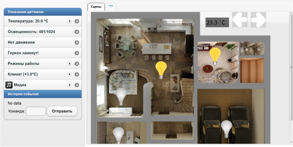
See how it works here: http://smarthouse.isystemsautomation.ru
There are several voice commands recorded on the voice module, which allow, for example, to turn on a light bulb - a controlled load in the socket, or to turn the camera left and right.
Part two
Further events developed rapidly for us. We showed the layout to some people, then to others ... the “social elevator” worked, and we were invited to participate in the “Open Innovations” forum in the Smart City section 3 weeks before the opening. We could not miss the opportunity to demonstrate their achievements. We began to creative, and an idea was born with the layout of the building, a fountain and elements of the engineering infrastructure of the city. Quickly enough we have gone from a sketch and a 3D model to the embodiment in “iron and concrete”.
So our thoughts were embodied:
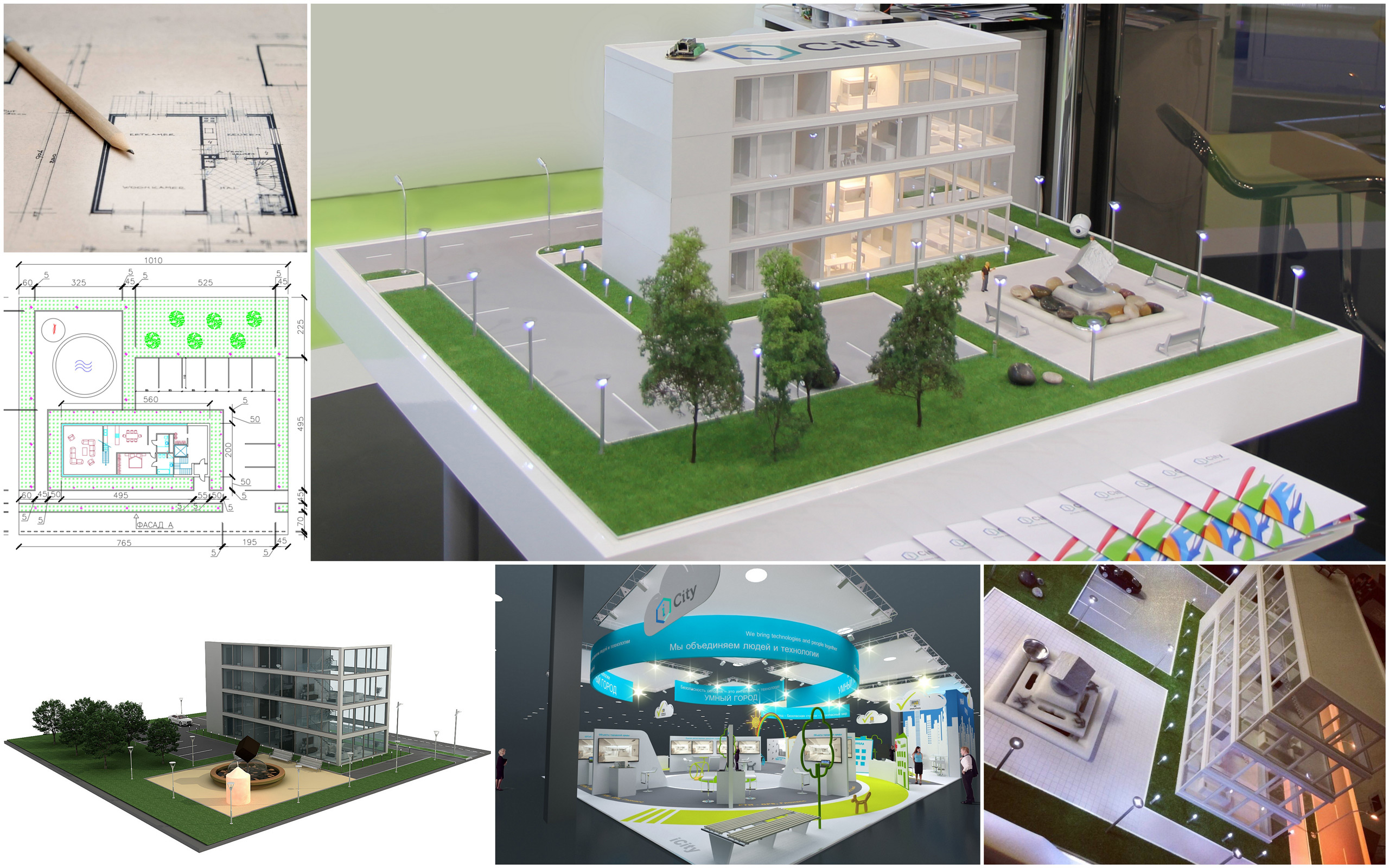
A block of 18 relays was used to control various groups of light.
From the sensors, we deduced the photoresistor and the temperature sensor on the layout. Another temperature sensor remained under the bench, so that you can compare the temperature difference.
Also on the layout there is a managed fountain. Next to the fountain is a water meter, which "symbolically" takes into account the flow of water. At the counter, you can stop more. It was chosen not by chance, but in order to demonstrate the most typical household use for our smart home system. It is a conventional water meter with a pulse output. The principle of its operation is very simple: once in 10 liters the counter closes the contact inside itself, the controller can easily read this pulse and add it to the stored value. It remains only to make it rotate. Of course, it would be possible to connect it directly to the compressor, which pumps the water in the fountain, but then the design would be complicated and unreliable. Therefore, an alternative solution was required. After opening the meter, it turned out that it consists of two mechanically unrelated parts: the meter itself in an airtight housing and a small impeller installed in the pipe. The counter rotated with a magnet mounted on the axis of the impeller. The decision suggested itself - to simulate the work of the counter, it is not at all necessary to mess with water, it is enough to disassemble it, removing the piece of pipe with the impeller and using a miniature motor to create a rotating magnetic field. As such an electric motor on hand was a small high-speed motor from the aviation model. Two neodymium magnets from a children's toy were stuck on its blades, and the motor itself was mounted in a plastic casing, which was docked on the back wall of the counter. As a result, we got a counter controlled from the controller (and its speed can be adjusted using PWM), which allows you to visually show how readings are transmitted and transmitted to the server
Graphical interface
For access to the floor plans of the layout, in addition to the web interface provided by MajorDoMo, we used our own development, the module for visualization of floor plans (MWPP), with a little “dopil” it for the corresponding tasks. It should be noted that initially the MUPP was developed and was part of the Automated Real Estate Management System for the corporate segment and was intended for a wide range of tasks, including:
- Space management;
- Managing the placement of employees / organizations;
- Management of engineering networks and equipment;
- Displays the geometry of the floor plan;
- Editing the geometry of the floor plan;
- Visualization and editing of workplaces;
- Display of attribute information (by buildings, floors, rooms, workplaces and technological places) stored in SAP modules;
- Editing attribute information and saving it in SAP;
- Construction of various analytical reports.
The architecture of the software package is as follows:

The MEPP web application is written using Java / JavaScript and published on Apache Tomcat, the server side of the module uses ESRI ArcGIS for Server, and the DBMS is Oracle with an extension for working with spatial data. Two-way communication between MFPP and SAP is implemented via web services, authorization of users to SAP is through, using the SAP SSO2 cookie. Here is how it looks.
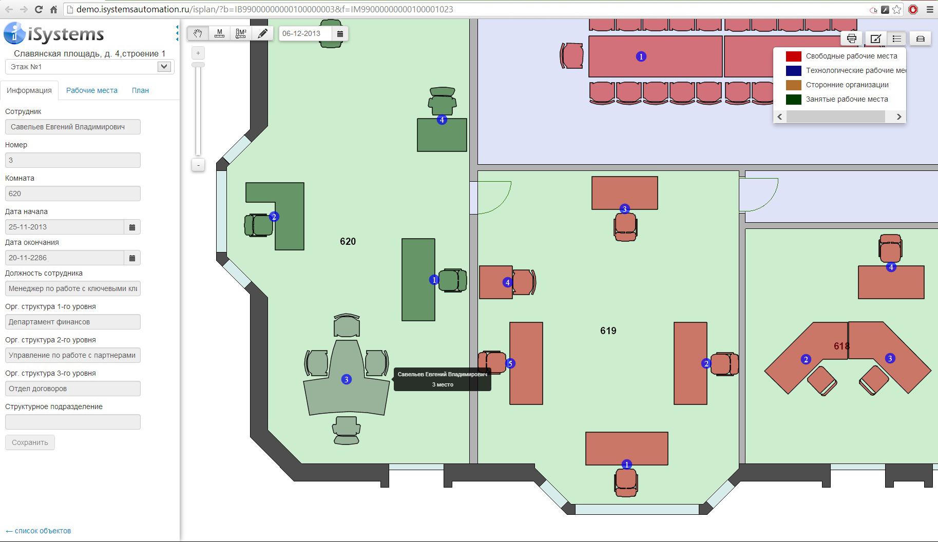
Below is the functional placement of jobs. All changes made to the floor plan in the FFP (changes in geometry, attributes, workplaces, etc.) are transmitted and saved to SAP.

If it is interesting for the Habras community, we will write down the implementation in more detail. For now those who wish can play with the application themselves.
So back to our layout.
The main functionality that we wanted to get from MUPP when using it in conjunction with the layout was as follows:
- Visualization of the floor plans of the building and the surrounding area;
- Lighting and fountain control;
- Monitoring the status of a set of sensors located on the layout (with the possibility of plotting graphs);
- View video from the surveillance camera installed on the layout (and control the rotation of cameras);
- Starting the transfer of information on the monitored sensors to the SAP SAP module (when the value of any indicator exceeds the limits of the maximum permissible values).
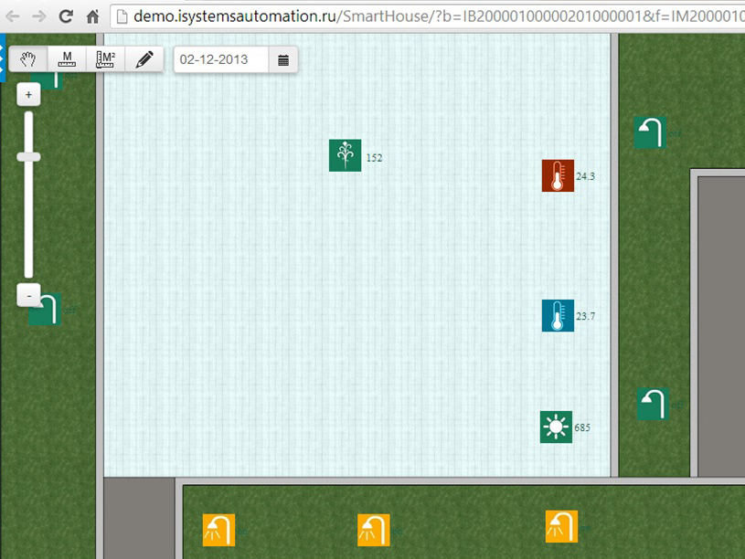
To use MUPP as a smart home control interface, we slightly refined it, expanded the spatial data model in the database (added a layer of sensors, street lamps, furniture, the adjacent territory, etc.) and in ArcMAP rendered four floors with the adjacent territory. identifiers with objects in SAP. The same was done with all the sensors.
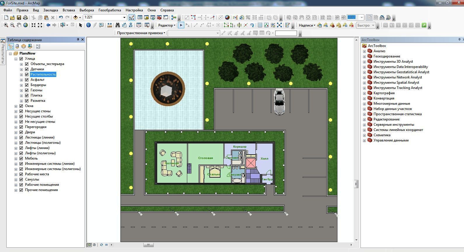
The lanterns were combined into three groups - along the perimeter, around the house and along the road. Accordingly, when you click on any lamp inside the group, the state changes on all the lights of the group (in the screenshot, the lights of the group “around the perimeter” are lit). When the sensor triggered in the parking lot, it was assumed that a car symbol appears on the corresponding parking space in the visualization interface. When you turn on the fountain on the layout, its symbol on the visualization interface should also come to life.
We wrote services for receiving information from the smart home controller with its saving information in the database (for simplicity, they used MS SQL) and services that transmit control actions (enable / disable) to the controller. Storage of the received information from the sensors is necessary for the ability to build graphs for past periods, which was also implemented. Consider more control of temperature and water flow.
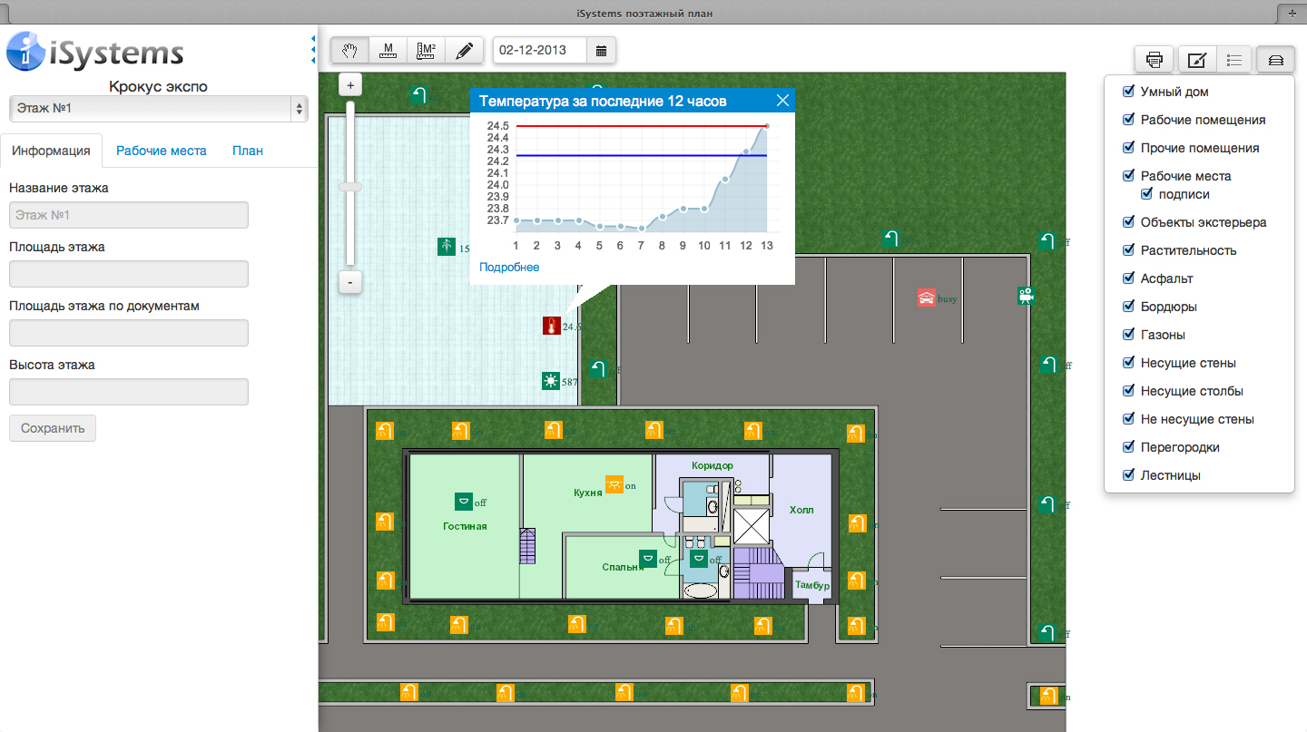
For each sensor, an individual adjustment of the boundary values was implemented.
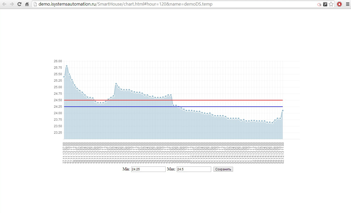
The sensors themselves on the plan are also highlighted in color in accordance with the status of being in a particular corridor (above the norm, the norm and below the norm).
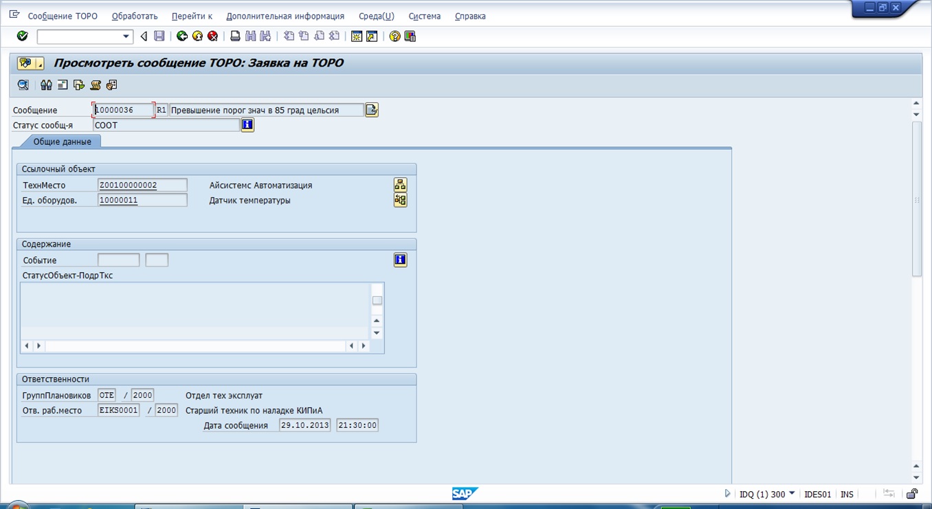
When the sensor value leaves the tolerance range (<20 and> 30 degrees Celsius), the creation service in the maintenance (SAP) of the corresponding incident starts.
In the visualization interface for each sensor, you can set boundary conditions and specify actions that should occur when these conditions are violated.
Also, for illustrative purposes, the transmission in the maintenance system is configured with a certain interval of values from the water flow sensor installed on the fountain.

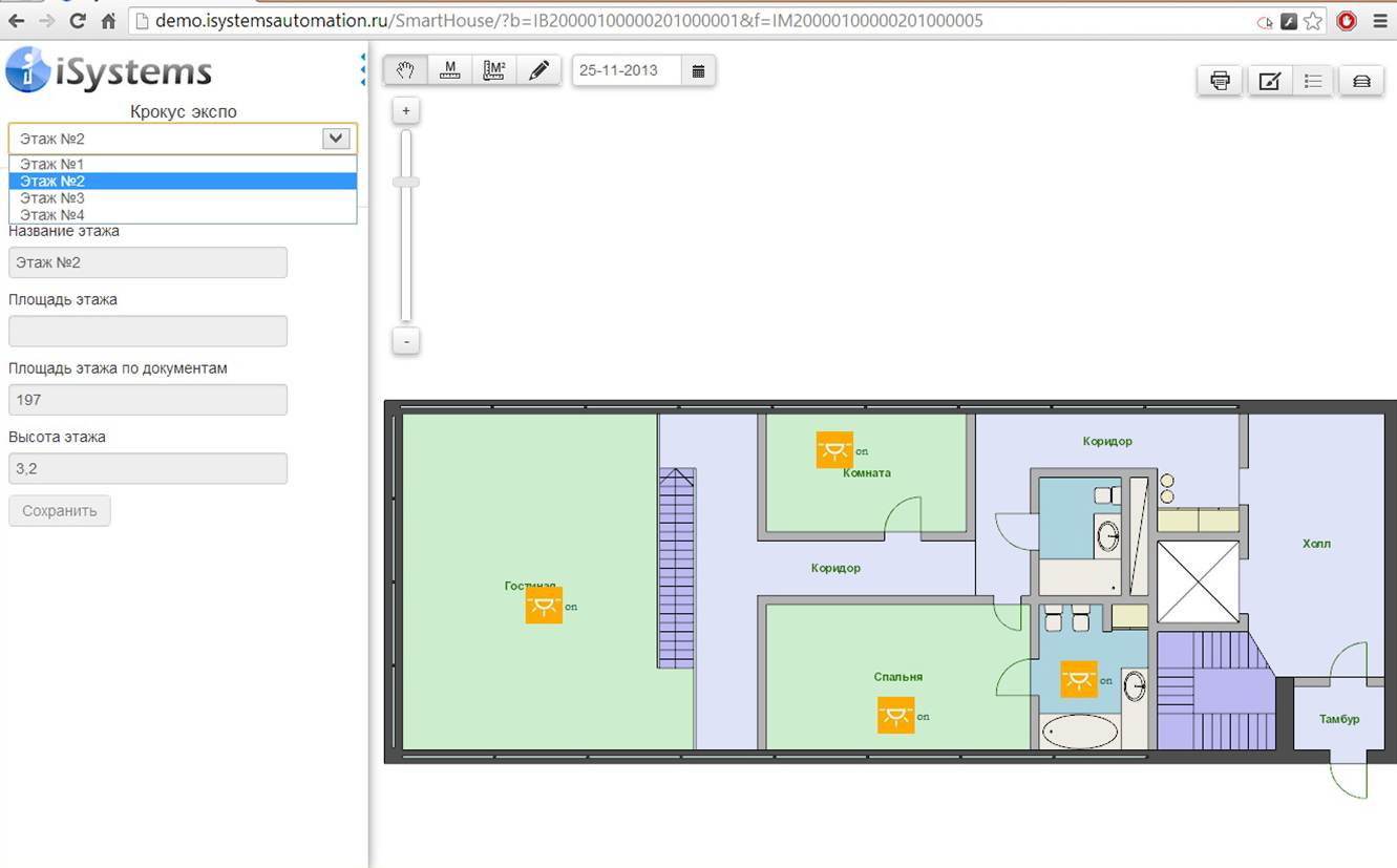
It is also possible to choose another floor.
Further plans are to completely abandon the use of MajorDoMo with the implementation of the necessary functionality (in MUPP), to work on the interface.
As a result, using a web application that can be launched in a browser on a computer or mobile device (in particular, on an iPad), we are able to remotely monitor the following parameters: the state of the light, the indicators from the sensors (water consumption, light, temperature, parking), surveillance cameras. Also, the web application allows you to control the lighting (both outdoor groups and lamps inside the building), turning the camera and the fountain.
We have worked on the forum for 3 days, and during this time, our mock-up caused great interest, both among specialists and bystanders. Those who immersed themselves in technical features could not believe that the entire management cycle (from sensors to SAPa) worked on the combat servers.
Frames with a spinning fountain, surprisingly, began most of the news on TV on the work of the forum. About us even removed a small story:
Working moments:

Conclusion
In the proposed material we tried to share the experience that we received as a result of the project for the construction of an energy-efficient and intelligent cottage. This project comes to an end, finishing and commissioning are completed. And in conclusion, I would like to share our development plans.
We see development in the following areas:
- Make a serial controller for a smart home as cheap and open as possible (OpenSource Hard / OpenSource Soft). Now we are negotiating with Chinese manufacturers, several versions are being worked out (Ethernet / Wifi + AC / DC). According to our plan, the cost for the end user should not exceed 500r per version with Ethernet.
- We are developing a touch panel with a screen, sensors and a microphone, which will replace the front faceplate covering the front panel of a standard size.
- We plan to produce ready-made solutions for specific tasks on the basis of this controller. For example, a heated floor controller will contain a relay, 3 temperature sensors, power from 220V and an Ethernet module (optional). The consumer will receive a ready-made solution for their task. Likewise for dimming light and leak detection.
- We plan to gather like-minded people and partners under the “one roof”, where we offer to jointly participate in the exchange of ideas on the development of residential and industrial infrastructure management systems aimed at safety, efficiency and ease of use. The working name of the project is iCity.
We are open to ideas and proposals in all areas, and also accept experienced specialists in our small team.
To analyze the demand, please leave your vote in the voting form.
Source: https://habr.com/ru/post/206694/
All Articles