Reverse engineering flashing LED
Cheap electronic "candles" lately seem to be everywhere. I did not pay much attention to them until I noticed that in fact they used a special LED - with a built-in blinker controller. Now it is a completely different matter: who does not like the mysterious LEDs? Half an hour later, I had already gathered an armful of twinkling Chinese-made LEDs.
Of course, the most interesting question is how do they work? Given that they cost literally a few cents apiece, there cannot be any expensive electronics inside. In this regard, another question arises: is it true that these LEDs are worse than numerous “candles” on microcontrollers, whose circuits are full on the Internet?
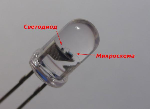
The device is relatively simple. The standard 5-millimeter case contains an LED crystal and a microcircuit, which is slightly larger than the first in size. The controller circuit is connected to both positive and negative terminals. The third jumper to it is connected to the anode of the LED, while the cathode "sits" on the negative terminal.
The Evil Mad Scientist blog recently had a story about similar LEDs. It showed how they “sing”, if you transform changes in brightness into sound. And also - how to use them to control a more powerful diode. Such tricks are based on the fact that the LED consumes more current in those moments when the controller lights it up brighter. A conventional LED, connected in series with flickering, shows very similar changes in brightness. In other words, the voltage drop across the resistor varies in proportion to the brightness.
')

This is what I used to extract the control signal from the controller and bring it to the logic analyzer (see the diagram above). By adjusting the variable resistor, I ensured that the analyzer perceived current surges as “zeroes” and “ones”, while the LED worked normally.
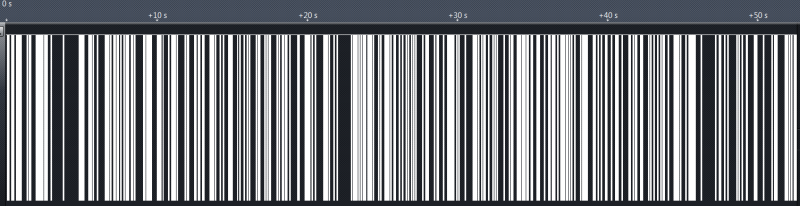
The diagram above shows changes in diode brightness over about a minute, recorded at a sampling rate of 1 MHz. The intervals when the LED is continuously on, and the periods when its brightness is somehow modulated, are noticeable. The LED never turns off for a long time. This is reasonable, because a real candle also shines brightly most of the time, reducing the brightness for short periods of flicker.
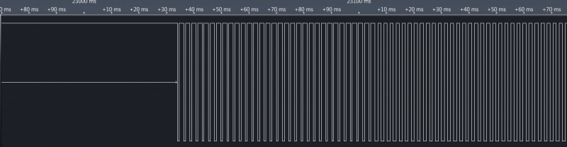
A closer look indicates that the signal has a pulse width modulation. This means that we have a digital circuit, without any analog tricks.
It is curious that the frequency of the signal is approximately 440 Hz, as in a standard tuning fork ( note of the first octave - approx. Transl. ). Coincidence? Or did the developer simply take a generator from some kind of musical scheme? So there is some truth in the stories about the "musicality" of these LEDs. Each “frame” of constant brightness is exactly 32 cycles and lasts about 72 ms. This corresponds to 13-14 frames per second.
I wrote a small program to determine the brightness in each frame by the fill factor of the PWM signal. The program reads a stream of samples from the logic analyzer and displays a series of real numbers, one for each frame.
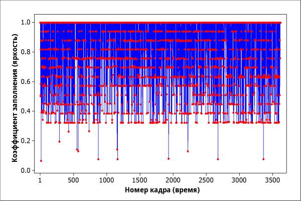
The graph of brightness versus time suggests some thoughts: changes in brightness are random, discrete, and have an uneven distribution. There seem to be 16 levels of brightness, the lowest 4 of which are used very rarely. Only 13 of the 3,600 counts correspond to them.

The construction of the histogram opens up the whole picture: only 12 levels of brightness are actually used. Exactly half of the frames has a maximum brightness, the remaining values are distributed approximately equally.
How can this be implemented at the hardware level? It is likely that a generator of uniformly distributed random numbers is used, which are passed through a simple shaper function. For the distribution that we are observing, at least 12x2 = 24 discrete levels are required. Half of them are displayed in one. This is quite curious, since the generator most likely produces binary numbers. The most logical would be the digit capacity of 5 bits, and these are 32 states. Displaying a 32-level discrete random variable of 24 levels without changing the distribution is not as simple as it seems. Do not forget also that this is not a critical scheme at all, and the developer probably did not have much time for a beautiful solution. Therefore, he used the simplest, a kind of hack.
The only simple way that comes to mind is to simply drop the wrong values and take the next random number. Unwanted values can be easily separated by a bit mask. Since the scheme is synchronous, there is only a finite number of attempts until the next frame begins. If the controller does not meet the specified number of attempts, it will get stuck on the “wrong” value. Remember the rare emissions on the brightness graph?
An ANSI-C implementation would look like this:
You can find out how many attempts are made? According to statistics, the proportion of a = 0.25 of all numbers must be discarded and re-generated. The probability that in n attempts the “correct” number is not chosen is equal to a n .
The proportion of anomalously low brightness levels is 13/3600 = 0.0036 , which coincides well with the option n = 4 . Thus, MAX_ATTEMPTS == 4 .
Note that a simpler solution would be to simply use the value from the previous frame if an invalid number was encountered. This option could be excluded on the basis of autocorrelation (see below). Probably the simplest solution — to change the PWM scheme — was not used here.
The last piece of the puzzle is the random number generator itself. A typical method for generating random sequences in digital circuits is to use linear feedback shift registers . Such a register produces a pseudo-random bit sequence, which will repeat no later than 2 x -1 clock cycles, where x is the digit capacity of the register. One of the features of such sequences (and good pseudo-random sequences as a whole) is that their autocorrelation function is equal to one only at point 0 and in coordinates that are multiple to the length of the sequence. In all other intervals it is zero.

I calculated the autocorrelation of the entire sequence of values. Self-similarity was not found up to 3,500 frames (only 1200 is shown in the graph above), which means the flicker is unique for at least 4 minutes. It is unclear whether further repetition of the sequence was observed, or whether the author’s logical analyzer simply did not allow writing longer - ca. trans. Since each frame requires at least 5 bits of random data (and given the mechanism for discarding unwanted numbers — even more), the pseudo-random sequence has a length of at least 17,500 bits. This will require a register of at least 17 bits, or a real hardware random number generator. In any case, it is interesting how much attention was paid during the development to ensure that the flicker pattern did not repeat.
In conclusion, we will answer the questions asked at the beginning of the article. The flickering LED turned out to be much more complicated than I expected (I also did not expect to spend 4 hours on it). Many candle microcontroller implementations simply feed the bits from the pseudo-random number generator to the PWM output. Purchased LED uses a more cunning algorithm to change the brightness. Of course, some attention was paid to the development of the algorithm, and at the same time a crystal of almost the minimum possible area was used. Share cent spent not in vain.
What is the best flicker algorithm? Is it possible to improve this?
Update: I finally found the time to write an emulator. An ANSI-C program that emulates the behavior of this LED is here . The code is written under AVR, but it is easy to port it to any other controller. The Github repository contains all the data and source codes used in the process of reverse engineering of the LED.
Of course, the most interesting question is how do they work? Given that they cost literally a few cents apiece, there cannot be any expensive electronics inside. In this regard, another question arises: is it true that these LEDs are worse than numerous “candles” on microcontrollers, whose circuits are full on the Internet?
The device is relatively simple. The standard 5-millimeter case contains an LED crystal and a microcircuit, which is slightly larger than the first in size. The controller circuit is connected to both positive and negative terminals. The third jumper to it is connected to the anode of the LED, while the cathode "sits" on the negative terminal.
The Evil Mad Scientist blog recently had a story about similar LEDs. It showed how they “sing”, if you transform changes in brightness into sound. And also - how to use them to control a more powerful diode. Such tricks are based on the fact that the LED consumes more current in those moments when the controller lights it up brighter. A conventional LED, connected in series with flickering, shows very similar changes in brightness. In other words, the voltage drop across the resistor varies in proportion to the brightness.
')
This is what I used to extract the control signal from the controller and bring it to the logic analyzer (see the diagram above). By adjusting the variable resistor, I ensured that the analyzer perceived current surges as “zeroes” and “ones”, while the LED worked normally.
The diagram above shows changes in diode brightness over about a minute, recorded at a sampling rate of 1 MHz. The intervals when the LED is continuously on, and the periods when its brightness is somehow modulated, are noticeable. The LED never turns off for a long time. This is reasonable, because a real candle also shines brightly most of the time, reducing the brightness for short periods of flicker.
A closer look indicates that the signal has a pulse width modulation. This means that we have a digital circuit, without any analog tricks.
It is curious that the frequency of the signal is approximately 440 Hz, as in a standard tuning fork ( note of the first octave - approx. Transl. ). Coincidence? Or did the developer simply take a generator from some kind of musical scheme? So there is some truth in the stories about the "musicality" of these LEDs. Each “frame” of constant brightness is exactly 32 cycles and lasts about 72 ms. This corresponds to 13-14 frames per second.
I wrote a small program to determine the brightness in each frame by the fill factor of the PWM signal. The program reads a stream of samples from the logic analyzer and displays a series of real numbers, one for each frame.
The graph of brightness versus time suggests some thoughts: changes in brightness are random, discrete, and have an uneven distribution. There seem to be 16 levels of brightness, the lowest 4 of which are used very rarely. Only 13 of the 3,600 counts correspond to them.
The construction of the histogram opens up the whole picture: only 12 levels of brightness are actually used. Exactly half of the frames has a maximum brightness, the remaining values are distributed approximately equally.
How can this be implemented at the hardware level? It is likely that a generator of uniformly distributed random numbers is used, which are passed through a simple shaper function. For the distribution that we are observing, at least 12x2 = 24 discrete levels are required. Half of them are displayed in one. This is quite curious, since the generator most likely produces binary numbers. The most logical would be the digit capacity of 5 bits, and these are 32 states. Displaying a 32-level discrete random variable of 24 levels without changing the distribution is not as simple as it seems. Do not forget also that this is not a critical scheme at all, and the developer probably did not have much time for a beautiful solution. Therefore, he used the simplest, a kind of hack.
The only simple way that comes to mind is to simply drop the wrong values and take the next random number. Unwanted values can be easily separated by a bit mask. Since the scheme is synchronous, there is only a finite number of attempts until the next frame begins. If the controller does not meet the specified number of attempts, it will get stuck on the “wrong” value. Remember the rare emissions on the brightness graph?
An ANSI-C implementation would look like this:
char attempts=0; char out; while(attempts++<MAX_ATTEMPTS) { out=RAND()&0x1f; if ((out&0x0c)!=0) break; // , 2- 3- } if (out>15) out=15; // You can find out how many attempts are made? According to statistics, the proportion of a = 0.25 of all numbers must be discarded and re-generated. The probability that in n attempts the “correct” number is not chosen is equal to a n .
n=1 0,25 n=2 0,0625 n=3 0,015625 n=4 0,003906 The proportion of anomalously low brightness levels is 13/3600 = 0.0036 , which coincides well with the option n = 4 . Thus, MAX_ATTEMPTS == 4 .
Note that a simpler solution would be to simply use the value from the previous frame if an invalid number was encountered. This option could be excluded on the basis of autocorrelation (see below). Probably the simplest solution — to change the PWM scheme — was not used here.
The last piece of the puzzle is the random number generator itself. A typical method for generating random sequences in digital circuits is to use linear feedback shift registers . Such a register produces a pseudo-random bit sequence, which will repeat no later than 2 x -1 clock cycles, where x is the digit capacity of the register. One of the features of such sequences (and good pseudo-random sequences as a whole) is that their autocorrelation function is equal to one only at point 0 and in coordinates that are multiple to the length of the sequence. In all other intervals it is zero.
I calculated the autocorrelation of the entire sequence of values. Self-similarity was not found up to 3,500 frames (only 1200 is shown in the graph above), which means the flicker is unique for at least 4 minutes. It is unclear whether further repetition of the sequence was observed, or whether the author’s logical analyzer simply did not allow writing longer - ca. trans. Since each frame requires at least 5 bits of random data (and given the mechanism for discarding unwanted numbers — even more), the pseudo-random sequence has a length of at least 17,500 bits. This will require a register of at least 17 bits, or a real hardware random number generator. In any case, it is interesting how much attention was paid during the development to ensure that the flicker pattern did not repeat.
In conclusion, we will answer the questions asked at the beginning of the article. The flickering LED turned out to be much more complicated than I expected (I also did not expect to spend 4 hours on it). Many candle microcontroller implementations simply feed the bits from the pseudo-random number generator to the PWM output. Purchased LED uses a more cunning algorithm to change the brightness. Of course, some attention was paid to the development of the algorithm, and at the same time a crystal of almost the minimum possible area was used. Share cent spent not in vain.
What is the best flicker algorithm? Is it possible to improve this?
Update: I finally found the time to write an emulator. An ANSI-C program that emulates the behavior of this LED is here . The code is written under AVR, but it is easy to port it to any other controller. The Github repository contains all the data and source codes used in the process of reverse engineering of the LED.
Source: https://habr.com/ru/post/206556/
All Articles