Electronics and seals: we collect a robot toy for a cat on STM32
Good afternoon, dear habrovchane.
A lot of time has passed since the last time I wrote articles on development here, it's time to fix this thing.
In this article I will talk about how I assembled a small robot on the STM32F101 microcontroller to entertain my Maine Coon, Arthas, about what problems they had to face and what came of it.
Background and formulation of the problem
Half a year ago I had this black handsome Maine Coon, whom I named Arthas after the famous computer game hero.

The cat is incredibly playful, loves to run, ambush and even bring a ball like a dog. Since I haven’t collected anything for a long time, it was decided to develop a small toy for a cat.
The main requirements for it were:
- Protection of critical parts of the structure from cat teeth and claws, ideally, fully enclosed body (ball)
- From the previous paragraph follows the requirement for small dimensions of the device, since it is desirable that it still was a small ball, and not a soccer ball.
- The ability to control from a mobile phone / tablet and desktop computer - in order not to reinvent the wheel and ensure compatibility with mobile devices, Bluetooth connectivity is ideal.
- To make it more interesting, it is desirable to have at least some sensor that would allow in the future to make the robot more or less autonomous, and not just a radio-controlled machine.
- Having some way to get the sound out to attract the attention of the kote.
')
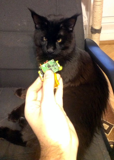
Immediately I will demonstrate a short video of what happened, the koshkob was launched in test mode (controlled by me, from a computer):
Koshkob tested without the outer shell, makes sounds cat attracts and can not escape because one of the drives fails.
(More about this at the end of the article)
Koshkob complete
It may seem to some that the cat is not very actively responding to the robot, but in fact the reason is that during the test it has already snatched it from me a hundred times, carried it away and gnawed. Of course, I took away the robot (until it is finished), so the cat, seeing the robot on the floor, decided to wait some time to make sure that it was not taken away from him as soon as he attacked)
Next, I will talk about the development process itself.
Development: selection of components and preparation
Housing
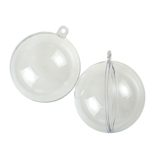
Having decided on the proposed design, I purchased a pair of plastic balls consisting of two halves — one with a diameter of 60 mm and the other with 80 mm, in case the first one fails to fit. Such dimensions greatly limited the choice of engines and sensors (in the sense that, for example, an ultrasonic sensor could be forgotten, it would not fit in the ball and, moreover, would not work in an enclosed space.
Microcontroller
After cutting off the "ear", the balls became ideal candidates for the role of the body. Due to the limited size, it was decided to design the entire schematic using the most compact cases, that is, for the most part, QFN.
STM32F101 was chosen as the central processor, since it is a microcontroller on the Cortex M3 core, and not a truncated M0, while it can operate at 36 MHz, has 64 KB of flash and 16 KB of RAM, and, most importantly, comes in 6x6 mm QFN -casing
Sensor
As a sensor, a three-axis accelerometer LIS331DL from the same ST was chosen, which was just a discount in Terraelectronics, so I got it at a price of about 30 rubles per item.
The accelerometer is available in a QFN case, 3x3 mm and can communicate via the I2C bus, which is very useful in conditions of limited dimensions. With the help of an accelerometer, it is possible to subtract the tilt of the robot along three axes, and it is also possible to try to get information from it about whether the robot is moving or has run into an obstacle (by changing the acceleration). And, of course, determine the time at which the cat kicks him to make a squeak - so the cat will consider it to be something alive)
Connection
As a means of communication, of course, we take proven, cheap and small Chinese modules HC-05
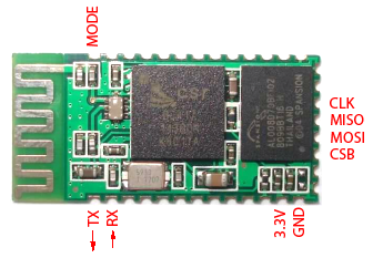
This is the only finished module in the robot.
Sound source
Initially, I wanted to use compact speakers, but, unfortunately, even the smallest speakers were still very large. In addition, they consumed a great deal and demanded at least a transistor and a filter in order to shake them with WMA. After some amount of googling, I found just such an entertaining piezo-squeaker:
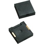
Murata's PKLCS1212E4001 costs 48 rubles, has dimensions of 11x11 mm (the largest element on the board!) And is a standard Piezo Sounder, a device that makes a sound due to the bending of a membrane by the piezoelectric effect. And this means that it consumes an order of magnitude less current than a speaker squeaking at the same volume.
But, in contrast to the dynamics of her very tricky and uneven frequency response, so that the best she knows how to squeak. And the loudest she gets to do it at 4 KHz (but this does not mean that you can’t squeak at others!)
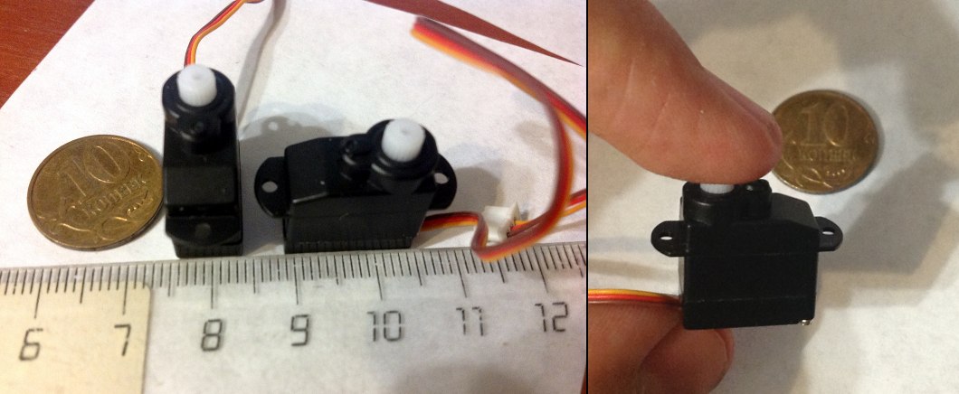
Drives
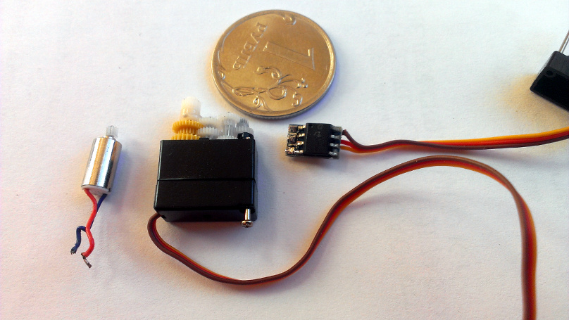
The most important element is the drives that will move the robot. Unfortunately, everything was not as smooth with them as we would like, more on this at the end of the article. As drives, I decided to take the smallest servos that I could find and remake them for constant rotation.
My choice is explained by the fact that by taking servos I get a motor + gearbox + control board in a housing of about 15x20x8 mm. With all the desire, I could not find a gear motor of such dimensions.
As a result, the choice fell on sub-micro servas , at the price of 187 rubles per share:
Nutrition
All elements are selected, it remains to decide how and what to feed the system. Obviously, the smallest lithium-polymer battery is the smallest and most suitable source. Since the drives require 4.8V, we increase the voltage to 5V with a compact DC-DC converter from MAXIM Semiconductors. The MAX8815 is a superb 3x3 mm microcircuit that allows you to load up to 1A with 97% efficiency (which, of course, depends on the correctness of the PCB layout, operation mode and choice of strapping, as always).
Since the drives consume no more than 600 mA together at peak times, this is more than enough.
To power the rest of the electronics and protect it from interference from the engines, after the DC-DC boost converter, we put a small-sized linear regulator from TI, LP2985 , with a fixed 3.3V output.
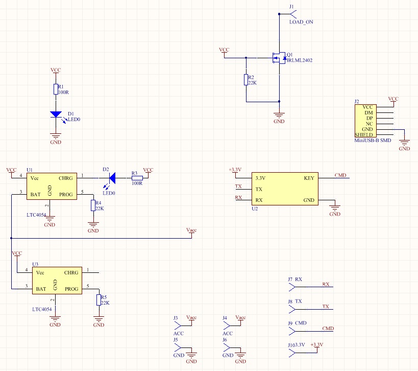
Circuit design and some design
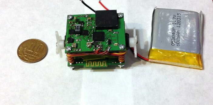
First, a few words about the design of the robot. In order to minimize the size and cost, I decided to use printed circuit boards as structural elements. That is, the drives are clamped between two printed circuit boards, which are fastened with screws. Assembled (and after debugging modifications of the board, which are later), it all looks like this:
To prevent the drives from moving down, I put wonderful material between the board and their surface - latex from the Torres expander

The fact is that once I bought a slingshot in China. The cattle was very comfortable, made of titanium alloy, but the rubber was not to hell there. On the Internet, experts on slingshots advised to immediately throw it out, to buy this very expander, and to cut out replacement harnesses from it. The result exceeded all my expectations and the slingshot became incredibly powerful. And since The expander is a big thing, then most of the material remained untouched and lay in a drawer, waiting for its time.
After using this latex as a gasket between the drives and the board, the drives stood up like a glove, not moving a millimeter.
Accordingly, for the implementation of this design requires two boards, in which all components are focused on the outer sides.
Once we have such a sudden increase in usable area, on the bottom board you can place a battery charger, a mini USB connector, charging LEDs, and at the same time bring a BT module so that it does not cover the battery and does not interfere with communication.
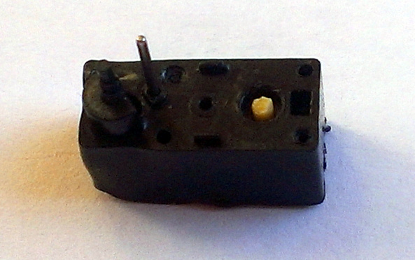
Thus, two PCBs, TOP and BOTTOM, were developed. On the bottom is what I have already said, and on the top is the whole “brain” and, so to speak, the digestive system of the robot - a microcontroller, an accelerometer, a converter and a power regulator strapping and, of course - a piezo-squeaker.
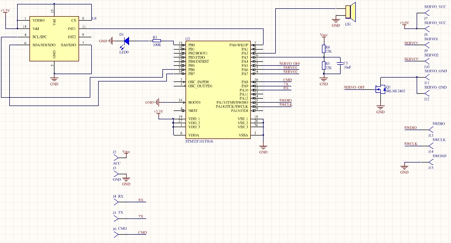
The scheme of the top board looks like this:
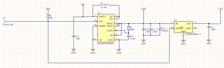
Power scheme
Brain
In order for USB not to drive its five volts where it is not necessary, the ON inputs of the U1 converter and the U2 regulator are connected, pulled up to power and brought to J1 on the edge of the board — the GND level feed puts the converter's inputs and outputs into a high impedance state, essentially breaking the circuit and letting the USB current flow where it should be — into the battery charging circuit. The rest of the connection scheme is typical of datasheet.
The U4 accelerometer is connected to the I2C bus of the controller without pull-up resistors - yes, they are necessary for the bus to work, but in the datasheet they assert that they are connected inside the LIS331DL . Strangely enough, there is no more information about them, I never recognized the nominal (and in the off state it is not measured, apparently, they are disconnected from the bus by transistors). So I had to blindly rely on datasheet. I must say, in this I did not lose - the accelerometer actually works fine without additional resistors.
However, another major fac-up was associated with it, which you can read about in the “Testing and Facs-ups” section.
In addition to the accelerometer, a D1 LED is connected to the controller, which is intended to visually attract the cat's attention and serve as a means of indication, as well as a voltage divider on resistors R4 and R5, which is connected to the ADC input of the controller through a smoothing capacitor C5. This divider leads the battery voltage to the range that ADC can measure, making it possible to judge the level of battery charge.
Incidentally, a mini-factor was connected with these resistors. The fact is that I assumed the presence in the controller of the built-in reference voltage (about 1.2 volts), as in the older models. But, as it turned out, in the models in the QFN36 case, there is no built-in source, and the REF input inside the case is shorted to the supply voltage (3.3V), so the resistors that at 4.2V battery gave 1V at the output had to be changed to those that give 3V .
The LS1 squeaker, thanks to its piezo essence, can be connected directly to the controller pin - its consumption is very small, at its resonant frequency its impedance is several hundred ohms. The only potential problem is that it can work in the opposite direction, that is, to generate voltage during deformation (shock), for which protective diodes or resistors are usually used. However, according to the results of the experiment, the voltage at the impact of an average force did not exceed 1.5V, which the protection diodes of the controller output can do well with, so I ventured not to put on additional protection.
The outputs from the onboard PWM generator of the controller are mapped to pins J8 and J9 to control the drives. As an additional (and, as it turned out, not superfluous) measures to reduce consumption in inactive mode, contacts J11 and J12, to which GND drives are connected, are cut off from ground by a power transistor Q1 - supplying a high level to the gate gives the drives a ground force and allows current flow through their insides. As it turned out, even at zero PWM signal, the control circuit of the drives still supplies some voltage to them and the consumption increases by 10 mA compared to completely disconnected ones.
An important point was the choice of debugging interface. In conditions of very limited dimensions, of course, I wanted to do with the minimum number of wires. But the information about the minimum amount turned out to be quite contradictory. After thoughtful googling and experiments, I stopped at the SWD interface, removing only the SWDIO and SWCLK pins. Related to this is another fac-up described in the section “Testing and Facs-ups”. But in short - yes, these two pins are really enough for debugging in most cases .
The bottom board is quite simple:
Bottom fee
It contains two parallel Li-Pol (Li-Ion) battery charging linear circuits connected in parallel, LTC4054 from Linear Technology. This is the easiest way to charge single-cell lithium-polymers and lithium-ions, known to me, if not pretty low efficiency (which is due to the fact that the chips are linear).
They stand perfectly in parallel, in some Chinese schemes saw as many as four similar mikruhi in parallel, providing a large charge current. Separately, each can give up to 800 mA, but this is only if you want to fry eggs on them. With a load above 500 mA and a fully discharged battery, the microcircuit begins to heat up so that it is impossible to hold a finger. Since A protection circuit for temperature is built into it, which, in principle, is not terrible - it will automatically reset the load current when it warms up to 120 degrees. But still this is not very pleasant, so I chose to put two pieces, since the place allowed. The charge current is set by resistors R4 and R5, selected by me so that it is about 500 mA for two (that is, 250 mA for each), at which they are not so heated.
In addition, the board has a mini-USB connector (J2), a Q1 transistor, a pull-up ON input of the power supply circuit on the top board to ground, with USB connected, and a Bluetooth communication module.
I ordered the boards at Rezonita, it came out quite budget-wise, I paid less than 2000r for a panel of six different boards, on which there were two boards from a cat-hobo.
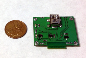
Top and bottom boards are 32x26 mm. After assembly (and before the fix-up fix), the top board looks like this:

And the bottom is like this:
It's time to write a test firmware!
Test firmware
I plan to make the final firmware based on FreeRTOS (so as not to waste time implementing normal multitasking, blocking queues and other things), but for the test I sketched a small firmware initializing all the peripherals and allowing it to be controlled by simple commands from the computer. Go through the initialization:
Clocking and GPIO
Code
void InitRCC() { RCC_APB2PeriphClockCmd(RCC_APB2Periph_GPIOA|RCC_APB2Periph_GPIOB, ENABLE); RCC_APB2PeriphClockCmd(RCC_APB2Periph_ADC1, ENABLE); RCC_APB1PeriphClockCmd(RCC_APB1Periph_TIM2|RCC_APB1Periph_TIM3,ENABLE); RCC_APB1PeriphClockCmd(RCC_APB1Periph_I2C1,ENABLE); RCC_APB2PeriphClockCmd(RCC_APB2Periph_USART1,ENABLE); RCC_APB2PeriphClockCmd(RCC_APB2Periph_AFIO, ENABLE); } void InitGPIO() { GPIO_InitTypeDef GPIO_InitStructure; //LED GPIO_InitStructure.GPIO_Speed = GPIO_Speed_50MHz; GPIO_InitStructure.GPIO_Mode = GPIO_Mode_Out_PP; GPIO_InitStructure.GPIO_Pin = GPIO_Pin_0; GPIO_Init(GPIOB, &GPIO_InitStructure); //ADC GPIO_InitStructure.GPIO_Speed = GPIO_Speed_50MHz; GPIO_InitStructure.GPIO_Mode = GPIO_Mode_AIN; GPIO_InitStructure.GPIO_Pin = GPIO_Pin_3; GPIO_Init(GPIOA, &GPIO_InitStructure); //Buzzer GPIO_InitStructure.GPIO_Speed = GPIO_Speed_50MHz; GPIO_InitStructure.GPIO_Mode = GPIO_Mode_AF_PP; GPIO_InitStructure.GPIO_Pin = GPIO_Pin_2; GPIO_Init(GPIOA, &GPIO_InitStructure); GPIO_WriteBit(GPIOA, GPIO_Pin_2, Bit_RESET); //Servo GPIO_InitStructure.GPIO_Speed = GPIO_Speed_50MHz; GPIO_InitStructure.GPIO_Mode = GPIO_Mode_AF_PP; GPIO_InitStructure.GPIO_Pin = GPIO_Pin_6|GPIO_Pin_7; GPIO_Init(GPIOA, &GPIO_InitStructure); //Servo On/Off GPIO_WriteBit(GPIOA, GPIO_Pin_5, Bit_RESET); GPIO_InitStructure.GPIO_Speed = GPIO_Speed_50MHz; GPIO_InitStructure.GPIO_Mode = GPIO_Mode_Out_PP; GPIO_InitStructure.GPIO_Pin = GPIO_Pin_5; GPIO_Init(GPIOA, &GPIO_InitStructure); //Accel GPIO_InitStructure.GPIO_Pin = GPIO_Pin_6 | GPIO_Pin_7; GPIO_InitStructure.GPIO_Speed = GPIO_Speed_50MHz; GPIO_InitStructure.GPIO_Mode = GPIO_Mode_AF_OD; GPIO_Init(GPIOB, &GPIO_InitStructure); //UART & BT Control GPIO_WriteBit(GPIOA, GPIO_Pin_8, Bit_RESET); GPIO_InitStructure.GPIO_Speed = GPIO_Speed_50MHz; GPIO_InitStructure.GPIO_Mode = GPIO_Mode_Out_PP; GPIO_InitStructure.GPIO_Pin = GPIO_Pin_8; GPIO_Init(GPIOA, &GPIO_InitStructure); GPIO_InitStructure.GPIO_Speed = GPIO_Speed_50MHz; GPIO_InitStructure.GPIO_Mode = GPIO_Mode_AF_PP; GPIO_InitStructure.GPIO_Pin = GPIO_Pin_9; GPIO_Init(GPIOA, &GPIO_InitStructure); GPIO_InitStructure.GPIO_Speed = GPIO_Speed_50MHz; GPIO_InitStructure.GPIO_Mode = GPIO_Mode_IN_FLOATING; GPIO_InitStructure.GPIO_Pin = GPIO_Pin_10; GPIO_Init(GPIOA, &GPIO_InitStructure); } Everything is simple here - we submit the clock to all the peripherals we need, that is, to the I / O ports, the ADC, the UART, a couple of timers (one for a tweeter, the second for PWM drives) and I2C. Then we set up all GPIO.
Squeaker
Code
void InitBuzzer() { TIM_TimeBaseInitTypeDef TIM_TimeBaseStructure; TIM_OCInitTypeDef TIM_OCInitStructure; TIM_TimeBaseStructure.TIM_Period = 4; TIM_TimeBaseStructure.TIM_Prescaler = 1800; TIM_TimeBaseStructure.TIM_ClockDivision = 0; TIM_TimeBaseStructure.TIM_CounterMode = TIM_CounterMode_Up; TIM_TimeBaseInit(TIM2, &TIM_TimeBaseStructure); TIM_OCInitStructure.TIM_OCMode = TIM_OCMode_PWM1; TIM_OCInitStructure.TIM_OutputState = TIM_OutputState_Enable; TIM_OCInitStructure.TIM_Pulse = 0; TIM_OCInitStructure.TIM_OCPolarity = TIM_OCPolarity_High; TIM_OC3Init(TIM2, &TIM_OCInitStructure); TIM_OC3PreloadConfig(TIM2, TIM_OCPreload_Enable); TIM_ARRPreloadConfig(TIM2, ENABLE); TIM_Cmd(TIM2, ENABLE); } Setup is reduced to the initialization of the timer, the output of which is connected to the squeaker. We adjust the PWM, but, in fact, it is the pulse width that will not be changed, always setting it to 50%. Instead, we will change the divider, forcing the timer to change the frequency of the pulses in order to squeak in a different tone.
Since the system frequency is 36 MHz, we set the period to 4 (we still do not need a lot of PIMA discharge), and the prescaler is 1800, receiving a frequency of 4 KHz.
Drives
Code
void InitServo() { TIM_TimeBaseInitTypeDef TIM_TimeBaseStructure; TIM_OCInitTypeDef TIM_OCInitStructure; TIM_TimeBaseStructure.TIM_Period = 0xFFF; TIM_TimeBaseStructure.TIM_Prescaler = 0xB0; TIM_TimeBaseStructure.TIM_ClockDivision = 0; TIM_TimeBaseStructure.TIM_CounterMode = TIM_CounterMode_Up; TIM_TimeBaseInit(TIM3, &TIM_TimeBaseStructure); TIM_OCInitStructure.TIM_OCMode = TIM_OCMode_PWM1; TIM_OCInitStructure.TIM_OutputState = TIM_OutputState_Enable; TIM_OCInitStructure.TIM_Pulse = 0; TIM_OCInitStructure.TIM_OCPolarity = TIM_OCPolarity_High; TIM_OC1Init(TIM3, &TIM_OCInitStructure); TIM_OC2Init(TIM3, &TIM_OCInitStructure); TIM_OC1PreloadConfig(TIM3, TIM_OCPreload_Enable); TIM_OC2PreloadConfig(TIM3, TIM_OCPreload_Enable); TIM_ARRPreloadConfig(TIM3, ENABLE); TIM_Cmd(TIM3, ENABLE); } We do the same thing as with the beeper, but we are already sharpening the output of PWM with the parameters required by the drives, namely, the frequency around 50 Hz, and a sufficiently large number of digits to control the speed with great accuracy. Thus, we set the prescaler to 176, and the period to 4096, which gives us approximately 50 Hz and 12 bits of PWM.
Accelerometer and Bluetooth
Code
void InitAccel() { I2C_InitTypeDef I2C_InitStructure; I2C_InitStructure.I2C_Mode = I2C_Mode_I2C; I2C_InitStructure.I2C_DutyCycle = I2C_DutyCycle_2; I2C_InitStructure.I2C_OwnAddress1 = 0x00; I2C_InitStructure.I2C_Ack = I2C_Ack_Enable; I2C_InitStructure.I2C_AcknowledgedAddress = I2C_AcknowledgedAddress_7bit; I2C_InitStructure.I2C_ClockSpeed = 200000; I2C_Init(I2C1, &I2C_InitStructure); I2C_Cmd(I2C1, ENABLE); } void InitBT() { USART_InitTypeDef USART_InitStructure; NVIC_InitTypeDef NVIC_InitStructure; USART_InitStructure.USART_BaudRate = 9600; USART_InitStructure.USART_WordLength = USART_WordLength_8b; USART_InitStructure.USART_StopBits = USART_StopBits_1; USART_InitStructure.USART_Parity = USART_Parity_No; USART_InitStructure.USART_HardwareFlowControl = USART_HardwareFlowControl_None; USART_InitStructure.USART_Mode = USART_Mode_Rx | USART_Mode_Tx; USART_Init(USART1, &USART_InitStructure); USART_Cmd(USART1, ENABLE); USART_ITConfig(USART1, USART_IT_RXNE, ENABLE); NVIC_InitStructure.NVIC_IRQChannel = USART1_IRQn; NVIC_InitStructure.NVIC_IRQChannelPreemptionPriority = 0; NVIC_InitStructure.NVIC_IRQChannelSubPriority = 0; NVIC_InitStructure.NVIC_IRQChannelCmd = ENABLE; NVIC_Init(&NVIC_InitStructure); } Everything is simple here - for the accelerometer, we simply turn on I2C for a speed of 200 KHz (although it is possible more and less, the axel allows), and Bluetooth is our usual UART, which we turn on for standard 9600 and at the same time set up intercept reception in which we will process commands.
Next, write the UART interrupt handling code. Of course, it is not the most successful, it will not hurt at least to check the checksum, but it will do for the test. In order not to waste time on the command queue, let's make it equal to one team - it still only affects how often you can throw commands to the controller and not be afraid that he will let them through.
Command Reception Code
Code
#define OPCODE 0 #define LENGTH 1 #define PAYLOAD 2 enum CommandStates {CS_DONE, CS_RECEIVING, CS_EXECUTING}; enum CommandCodes {CC_TEST=0x01, CC_SERVO_STATE, CC_SET_SERVO1_DS, CC_SET_SERVO2_DS, CC_GET_ACCEL_REG, CC_SET_ACCEL_REG, CC_GET_BATTERY, CC_LED_STATE, CC_BUZZER, CC_INVALID}; enum ErrorCodes {EC_NONE, EC_INVALID_CMD, EC_MAX_LEN_EXCEEDED}; enum ReplyCodes {RC_NONE, RC_EXECUTED, RC_TEST, RC_ACCELREG, RC_ERROR}; typedef struct { unsigned char Command; unsigned char State; unsigned char Length; unsigned char Payload[CMD_BUFFER_LEN]; }CommandDescriptor; CommandDescriptor Cmd; void InitCmd(CommandDescriptor *Comm) { Comm->Command=0; Comm->Length=0; unsigned char i; for(i=0;i<CMD_BUFFER_LEN;i++) Comm->Payload[i]=0; Comm->State=CS_DONE; //Init state at the end, to prevent interrupt from interfering } void SetInvalidCmd(CommandDescriptor *Comm, unsigned char ErrorCode) { Comm->Command=CC_INVALID; Comm->Length=3; Comm->State=CS_EXECUTING; //Just send back error Comm->Payload[0]=ErrorCode; } void USART1_IRQHandler(void) { char data; if ((USART1->SR & USART_FLAG_RXNE) != (u16)RESET) { data = USART_ReceiveData(USART1); switch(Cmd.State) { case CS_DONE: if(data>=CC_INVALID) { SetInvalidCmd(&Cmd, EC_INVALID_CMD); return; } Cmd.Command=data; Cmd.Length=0; Cmd.State=CS_RECEIVING; return; case CS_RECEIVING: if(Cmd.Length==0) { if(data>CMD_BUFFER_LEN) { SetInvalidCmd(&Cmd, EC_MAX_LEN_EXCEEDED); return; } Cmd.Length=data; BufPtr=0; return; } if(BufPtr<Cmd.Length-2) //Including opcode and length fields { Cmd.Payload[BufPtr]=data; BufPtr++; } if(BufPtr>=Cmd.Length-2) { Cmd.State=CS_EXECUTING; return; } case CS_EXECUTING: return; } } } , CC_SET_SERVO1_DS, CC_SET_SERVO2_DS, CC_GET_ACCEL_REG, CC_SET_ACCEL_REG, CC_GET_BATTERY, CC_LED_STATE, CC_BUZZER, CC_INVALID}; #define OPCODE 0 #define LENGTH 1 #define PAYLOAD 2 enum CommandStates {CS_DONE, CS_RECEIVING, CS_EXECUTING}; enum CommandCodes {CC_TEST=0x01, CC_SERVO_STATE, CC_SET_SERVO1_DS, CC_SET_SERVO2_DS, CC_GET_ACCEL_REG, CC_SET_ACCEL_REG, CC_GET_BATTERY, CC_LED_STATE, CC_BUZZER, CC_INVALID}; enum ErrorCodes {EC_NONE, EC_INVALID_CMD, EC_MAX_LEN_EXCEEDED}; enum ReplyCodes {RC_NONE, RC_EXECUTED, RC_TEST, RC_ACCELREG, RC_ERROR}; typedef struct { unsigned char Command; unsigned char State; unsigned char Length; unsigned char Payload[CMD_BUFFER_LEN]; }CommandDescriptor; CommandDescriptor Cmd; void InitCmd(CommandDescriptor *Comm) { Comm->Command=0; Comm->Length=0; unsigned char i; for(i=0;i<CMD_BUFFER_LEN;i++) Comm->Payload[i]=0; Comm->State=CS_DONE; //Init state at the end, to prevent interrupt from interfering } void SetInvalidCmd(CommandDescriptor *Comm, unsigned char ErrorCode) { Comm->Command=CC_INVALID; Comm->Length=3; Comm->State=CS_EXECUTING; //Just send back error Comm->Payload[0]=ErrorCode; } void USART1_IRQHandler(void) { char data; if ((USART1->SR & USART_FLAG_RXNE) != (u16)RESET) { data = USART_ReceiveData(USART1); switch(Cmd.State) { case CS_DONE: if(data>=CC_INVALID) { SetInvalidCmd(&Cmd, EC_INVALID_CMD); return; } Cmd.Command=data; Cmd.Length=0; Cmd.State=CS_RECEIVING; return; case CS_RECEIVING: if(Cmd.Length==0) { if(data>CMD_BUFFER_LEN) { SetInvalidCmd(&Cmd, EC_MAX_LEN_EXCEEDED); return; } Cmd.Length=data; BufPtr=0; return; } if(BufPtr<Cmd.Length-2) //Including opcode and length fields { Cmd.Payload[BufPtr]=data; BufPtr++; } if(BufPtr>=Cmd.Length-2) { Cmd.State=CS_EXECUTING; return; } case CS_EXECUTING: return; } } } To begin, we will declare the structure of the command, which will consist of, in fact, the command itself, the state (completed, in the process of receiving, during processing), the packet length (including the two fields already listed) and the payload, which can be from 0 to 8 bytes .
We describe a helper function for initializing this structure and another one for filling it with Invalid Command values.
Now we describe the interrupt. Having received one byte on the UART, let's see what happens with the current command (the one and only one in the “queue”) -
if its status tells us that the execution has been completed, then we will check if we received the correct opcode, if not, we will report an error, if yes, we will begin to receive a new command, setting the status to CS_RECEIVING .
If we are in the process of receiving, we control the length of what we get - so that it does not exceed 10 bytes (2 bytes of the header and payload) and the length declared in the second byte of the header. If something is wrong, we report an error, otherwise we say that the command has been received and has passed to the CS_EXECUTING state. From this point on, we ignore everything that comes to us, until someone sets this team to CS_DONE .
If we had a real queue, it would be possible to throw the received command into it and for now take the following.
That's all - the main function of the firmware simply initializes the peripherals, turns on the Bluetooth and waits until the command has the status CS_EXECUTING . After that, it processes the command (I will not give this code, there is just a big switch on opcodes with entering bytes from the payload to the registers) and sets it to CS_DONE status.
void main ()
Code
int main(void) { InitCmd(&Cmd); InitHardware(); DisableServos(); EnableBT(); EnableLED(); while(1) { if(Cmd.State==CS_EXECUTING) { ProcessCmd(&Cmd); InitCmd(&Cmd); } } } Modification of drives for constant rotation and design issues
Since the drives were originally designed to rotate within 170 degrees, they need to be slightly upgraded in order to use them as robot engines. Because of their small size, this may not be very easy at first.
In general, all drives are built in the same way, regardless of size - they have a motor, they have a gearbox, the output shaft of which sits on the same axis with a variable resistor, from which the control circuit removes information about the current position of the shaft.
The resistor is turned on as a divider between power and ground. On one of the gears on the output shaft, there is a stopper that does not allow the server to spin further than it should be, and the potentiometer itself acts as such a stopper. Specifically, in these drives everything is rather trivial - the stopper is an outgrowth on the output shaft, it is large enough, so it’s easier not to cut it, and then - what it rests against, the protrusion inside the drive cover
This protrusion is easily melted by a soldering iron, the main thing then is to make sure that there are no pieces of plastic left that will interfere with the rotation.
The potentiometer shaft contains a small cut at the end, due to which it is not turned in the gear of the output shaft. By the way, it is located in a small depression in which this gear comes in. Therefore, we simply cut / fuse it with a soldering iron until a trace of this cut remains. Everything, the gear wheel quietly turns, without touching the variable resistor.
Lubricate everything additionally, because The Chinese feel sorry for the grease, close the top cover. There are very few.
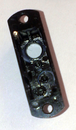
Open the bottom cover, see the control circuit connected to the motor and potentiometer.

Ruthlessly cut off the wires from the potentiometer, remove them from the servos so as not to interfere. To the contact pads to which they walked, we solder two identical small SMD resistors, with a total resistance of about 5 KΩ (if a little more or a little less is not terrible), forming a permanent divider. I soldered two for 2.4Kom.
Since the motors will lie mirror relative to each other, one of them also swaps the wires going to the motor. You can, of course, do this software, but it is ironier more pleasant.
That's it, now the serv will always assume that its shaft is exactly in the middle. And by submitting a PWM signal with a duty ratio greater than the average, the output shaft will begin to rotate in one direction, and at less - in the other. And the more the filed value is separated from the average, the faster the shaft rotates.
Testing and Facs

Customer tests device prototype
Since I have already demonstrated the video and photo of the device above, this section will mainly contain a text description of the rake I stepped on. Some of them occurred through my fault, some did not depend on me.
Fak-up with food
The very first factor-up, entailed the most improvements in the scheme. Connected to the boost converter. When I first started the device (so far without drives), I didn’t notice anything, the controller started up and flashed. 5B were present at the output of the converter. The time has come to check the drives, this is where the rakes came out. When connecting the drives, the converter was instantly cut off - its built-in protection triggered, disabling the microcircuit, in case the output voltage drops more than 10 percent below the set point (5V). Debugging took me a very long time, including sitting at an oscilloscope, replacing the converter chip itself with a similar one, testing different chokes, etc.
Interestingly, even the containers hung around the drives did not help, so I decided that the problem was in the PCB layout or in the choke. Measurements have shown that the converter stops working at a load of more than 90 mA, and even in the case of a pure resistive load! At the same time, the efficiency was about 40 percent, of course, this is unacceptable for a pulse converter.
The reason turned out to be incredibly commonplace - it seems that instead of the output ceramic capacitor of 10 µF, I mistakenly soldered the same to 1 µF. With such an output capacitance, the microcircuit could not reach the mode, and the large capacitors mounted on the snot did not help it at all.
Lightly stripping the board from the mask, I soldered two 22 microfarads of ceramic capacitor to the converter output, to its input, and right in front of the servos.
At the same time I set a smoothing choke (more precisely, ferrite bead), BLM41PG471SN1 , calculated for 2A, between the output of the converter and the servers.
In addition, as it turned out, the place on the board allows you to push there one tantalum capacitor in the “A” case, 150 μF, right next to the converter output.
In fact, one 22 microfarad capacitor at the output and one at the input would be enough for correct operation, but since space allowed, I decided to play it safe.
The result was just great, the 5V output, even under load, was almost not noisy, and the converter's efficiency, according to my measurements (I included ammeters in the input and output circuits), reached 93 percent, which is a very good figure in itself.
Conclusion from the FAQ: Check which elements are soldered to the board. Pulse converters are sensitive, and the components mounted on snot will not improve the situation, even if the direction of thought (insufficient output capacity) was correct.
The resistance of the probes and the shunt of the multimeter, the capacity and inductance of the prototypes distort the picture, so it is necessary to test such things in the final configuration, and not on snot.
Fac-up with accelerometer
Hemorrhoid fak-ap, again because of inattention. When testing the periphery, it turned out that the accelerometer is not responding. Since He sits on the I2C bus, the conversation begins (not counting the starting impulse) by passing the address of the device. After that, it should respond with a confirmation pulse, if the address coincided. There was no impulse.
Since the accelerometer case was the most disgusting for soldering (3x3 mm and there was no earthen pad on the belly of the chip, which made it disgustingly centered), I decided that the problem was soldering and spent a lot of time re-soldering it several times. Did not help.
Then I decided that the promised built-in resistors were still insufficient, cleaned the board and soldered their own. Did not help.
Many times I checked the code and checked the address with the datasheet. Did not help.
As a result, by some miracle, he gave an address that differs from the one given (in one of the digits of the binary representation of the address). It helped.
I started digging datasheets, because this simply could not be - so that the device responded to another address. And found a great thing.
It turns out that there are two modifications of the accelerometer: LIS331DL and LIS331DLH .
The same case. Same datasheets. . 2g/4g/8g, — 2g/4g.
. , LIS133 «LIS133DLH», , .
-: . — , . , .
- Bluetooth-
- . , , HC-04, HC-05, HC-06 — , . .
HC-04 HC-05, , 04 , , 05 GPIO, 05 , , 04 ( , ), .
.
, , — 20 40 .
RESET . RESET .
-: — . , , , — .
-
-, . , SWD — . , (ST-LINK ), VAPP . , - 3.3. , , — .
. NRST , , , . SWD , , . But.
. , 32, Debug support for low-power modes : The core does not allow FCLK or HCLK to be turned off during a debug session. As these are required for the debugger connection, during a debug, they must remain active.
, Stand-By, . And since -, .
— - , - ( ), , NRST .
, , , -, . GND, , - . , , .
-: , , . , , .
-
-, . , , . -, , . . , , . — , ( , ) .

, , — , . . , 1-2 . , MG90, , .
( , ) .
, , - .
-: , , . — . , , , .
: — . , . , )
— ( ) — , . . — , . — . . , .
, ( ). — , v1.5, FreeRTOS!
, !

Source: https://habr.com/ru/post/206128/
All Articles