Altium Designer: the largest application (about 15,000,000 codelines) made in Delphi
Embarcadero always happily mentions the Altium Designer product when it comes to successful commercial applications created in Delphi. The scale of the project cannot but amaze - it has about 15,000,000 (fifteen million) lines of source code. Altium Designer is a CAD system for designing printed circuit boards of electronic systems, including 3D modeling. Today we will talk about the technical component of the system from the position of software engineering.
The purpose of this article is not in any way the promotion or advertising of Altium Designer, which is already well known among professionals in this field. We will conduct a kind of excursion deep into the project and get acquainted with the peculiarities of its implementation in the context of the complexity of the task and the scale of implementation. This will be especially useful for novice developers, as well as professionals interested in large systems in all respects (and not just big data).
')
Let's immediately assess the scale of the system in the context of its functionality. Please describe the main functional modules or subsystems. This is very important because The term CAD (computer aided design) has a fairly broad meaning - so can be called a simple application “drawing”, and intelligent CAD. What can Altium Designer do?
The engineer receives or formulates the specification of the device, starting from the conditions in which it should work, ending with the element base that you plan to use. Now very often the development is carried out from a microprocessor - a chip is selected that solves the necessary task, and the harness is designed for it. After that, a library of used components is created, a logical / schematic diagram is drawn in the schematic editor. It also specifies clarifications and limitations that can affect how the board will be “divorced” physically. Different types of analysis can be performed - signal integrity, circuit simulation. After that, the PCB begins to be created, i.e. sets the number of used layers according to the specification, locates components, identifies tracks that transmit a signal, supply power, etc. Those. already formed the physical representation of the board. After that, documentation is generated, files are sent, which are sent to the production / printing of boards, a list of components used for assembly lines is built.
One of the advantages of AD is that all the above operations are performed in one product in very tight integration with each other.
The main functional blocks of the system:
Is it possible to say that each of the functional subsystems is rather isolated modules? Is it so? If so, how are the modules implemented? Are these dll-plugins to some core? Are these equivalent applications? What is the data exchange mechanism between them?
Like most large systems, Altium uses a modular architecture. There is a platform that provides the basic infrastructure (documents, settings, message subsystem, etc.) and modules that implement the functionality. In recent versions, each module is an isolated dll providing a set of interfaces. Interfaces are not COM compatible, but interoperable. Several products are built on this platform, but the largest is AltiumDesigner.
A little more about how modules are combined. Is there some kind of internal API? It is very likely that in Altium each subsystem is developed by a separate team. Do you have a general idea? Or some exchange protocols between modules? Is there network interaction?
Yes, of course there is an API used inside. Basis - interfaces with some restrictions on the types used. Quite widely used system of commands / messages.
Considering that, besides Altium Designer (AD), there is a fairly wide range of supporting products in the company's solution stack, ranging from a license server to an infrastructure that provides the Altium.Live ecosystem, there is a lot of networking. Web services are actively used. For internal products, is this the most common SOAP protocol, with external services? recently - REST.
How is the storage of projects organized?
Everything is quite simple here, there are several SVN repositories divided into application areas: platform, product core, extensions, web projects. Task management in Assembla, actively using Google docs.
There are several internal support services - the collection of "crash reports", "build system", the test run system on the "test-farm".
When we talk about a full-scale environment, simple, but interesting questions arise. How many menu items are in the main system window? How many windows are in the application? Understandably, nobody specifically thinks, but just interesting. It's like "the construction of the television tower went so many millions of rivets or bolts." How are you with such formal parameters?
Frankly, few people are engaged in such calculations. Although the colleagues involved in documentation may know about this - they have to keep all these dialogues up to date :)
Search for dfm files in the two main repositories gives the numbers ~ 500 for the platform and ~ 1800 for the main product . The number of menu items is somehow quite difficult to calculate, especially since it is dynamic, and depends on the open document, mode of operation, etc. But there are really a lot of them :)
In the basic configuration of the order of 150-200 dll-modules , in the base repositories there are about 500 dpr-projects , the full “build” of the product takes 40 minutes (although this is really complete, the result of this “build” becomes available to users in the update system).
You can imagine any screen-shot of the system window with the loaded scheme. Is this a typical object CAD window? Main working graphic field, toolbar, object property editor? Or are there some features?
Basically, the work is carried out with the logical scheme of the project (the first screenshot) and its physical implementation (the second screenshot). There are certainly many other areas, but these are key.
In the second screenshot (below) - a 3D representation of a flexible-rigid board. The design itself is usually conducted in 2D mode.
Did you use standard Delphi components or did you use additional libraries to increase the level of ergonomics of the interface?
From visual - DevExpress and DreamControls components are quite widely used, there are quite a few self-written controls.
drawing model - used the “outline” or some GPU-based library (OpenGL, DirectX)?
Now for circuits - GDI / GDI +, for PCB - DirectX.
How open is the system? Can I create my own custom plugins?
It was quite open earlier, now there are quite a few extensions, most often of an integration nature. And in recent versions this has been emphasized - we have an SDK for Delphi, C ++ and C #. In the coming days, there is a version of DeveloperEdition, which will make the development of extensions even easier.
Is there a custom automation mechanism? Any scripts, macros, internal programming language?
Yes, there is, quite popular with users, Delphi / Basic / Java-script . It is used both for writing extensions and for everyday work, in particular, for defining complex filters by objects.
Let's talk about the history of development. How did the project start?
The company, like the product, began a long time ago, in the 85th year when available personal computers appeared and there was a need to automate the creation of printed circuit boards. One of the first company created ECAD under Windows, then it was not such an obvious step as it seems now. Next was access to the Australian stock exchange, a series of acquisitions of companies and technologies, building an integrated stack of technologies for the development of electronic devices.
From which version of Delphi and for what is the development of Altium Designere? It is clear that such a large-scale project is difficult to migrate, but have there been successful attempts?
If I'm not mistaken, the first versions of the product were created on TurboPascal, then a series of Delphi versions starting from the 3rd. At the moment, this is Delphi 2010. Migrations usually occurred when it was justified from a pragmatic point of view - the necessary technologies appeared, critical errors were corrected. Any, even a minor modification of the backbone classes makes you think hard and very carefully approach the decision, up to a very accurate calculation of labor costs. We take into account that there are also third-party libraries. While we are not in a hurry with the transition to the latest version.
But besides Delphi uses quite a lot of languages and environments, for example, some of the modules are implemented in C ++ and C #, Morfik is used for some web services and applications.
How is the architecture of the core modules organized? Are these classic versions of the "form-control-action-response-procedure" type or are there more sophisticated techniques such as separation of the model and interface?
In such a large project there are many approaches. One of the key is the separation of the description of commands and the code of their executing. The main command bars and menus are described in external, configurable files, for documents there is a more or less clear separation of the model and the display, the auxiliary isolated dialogs are usually implemented with a classic event form.
Is the interface of the environment basically static or is there a dynamic mechanism for generating a user interface depending on the external configuration?
Part of the interface depends on which document is open (for example, for PCB and BOM, the set of commands and menus is radically different), and what functionality is available with an active license. Those. some basic framework provided by the platform is unchanged, the rest is determined by the mode and logic of the module.
What complex, scientific, with elements of artificial intelligence or just interesting algorithms are used in the system?
Not quite sure about the use of AI, but there are several areas in which the algorithmic framework is quite complicated, especially in the field of PCB and simulation. For example, automatic layout of boards - the area is very capacious in terms of algorithmic. When implementing it, it is necessary to solve not only the task of placing tracks in space (now most boards are multi-layered, and the track can change layers), but also take into account the enormous number of user-defined constraints - the minimum distance between tracks, track impedance, the “noise” of the resulting topology at high frequencies, etc ... This area has not been fully resolved yet.
Are there opportunities to optimize, for example, the overall size of printed circuit boards and structural elements? Multi-parameter optimization? Dynamic constraint setting?
Frankly, I don’t particularly remember any optimizations, especially in size. I would even say that the dimensions often come “outside” - in the form of a specification, a mechanical model of an existing device, the size of the chip used, an interface connector, etc.
Very often, a project can begin with the assignment of a set of restrictions constraint driven desing. The engineer determines the restrictions, sometimes quite complex, and the product helps them to comply or prohibits breaking. For example, one of the simple checks is the width of the track between certain components or the allowable angles when setting up the RF paths.
What are the possibilities for connecting external production equipment to the system? Is it possible to use the system as part of a stand, when an engineer submits a formal description of the task to the input, and a ready-made scheme implemented “in hardware” at the output?
Production - no more than yes. This is still an area, though adjacent, but far from that on which we focus - design and development. It is rather difficult to control the modern assembly line when the automaton applies solder to the finished boards, places the components, and then bakes the board according to the technical process, and does not intersect with the development of the board itself. Although there is certainly support for the manufacturing stage, this is one of the most important parts of the process - the export and preparation of data for the manufacture of boards, for assembly production, for test benches, etc.
From the connected equipment, mention can be made of the Nanoboard , a device used for development using programmable logic (FPGA / FPGA).
Have you thought about the implementation of a mobile front-end? It is known that for many CAD-systems there are already mobile versions of client workstations. Their usefulness is not yet sufficiently obvious, but perhaps you have your own vision of the applicability of mobile applications within large CAD systems or even CAD systems?
Currently there are no such plans. As you yourself noticed, the purpose and necessity of them is not entirely clear. To use them especially, it will not work, as replacing paper drawings in MCAD is also ...
There are mobile development departments in the company, but this is a separate area in the neighboring area that is not directly related to AD.
I can assume that you have a very developed object structure. Do you use graphical notation for interaction between developers? Or is the qualification of programmers such that the existing distribution by areas of responsibility and functionality of the modules allows the source code to use a single source of knowledge about the system?
No, graphic notation is not used. As practice shows, in our case, more effective is direct communication and a sufficient level of development skills.
The more complex the system, the more stringent the requirements for testing, especially regression. How is your process? Automatic tests, manual tests, the ratio between developers and testers?
Although we also have automatic testing covering key areas, manual regression testing, advanced beta testing, in my opinion, testing is one of the areas in which we could improve the situation. For example, one of the problems that we are trying to solve now is the involvement of QA engineers in the early stages of development.
What is the personnel policy of Altium? Do you have a fairly closed team? Or are you always open and ready to hire a decent specialist?
In this area, the company is more than open. As far as I know, at the moment we are actively looking for developers of high qualification in the Kiev and Shanghai offices. By the way, a funny moment - it turned out that a significant part of the core of the R & D of our Australian company is now made up of Russian-speaking engineers.
First of all, you are expanding the staff at the expense of professionals or there are vacancies for beginners who are just starting to build their career in software development?
Usually, developers come to the company either with good skills and experience or possessing any unique competencies. Beginners to join the rhythm and the task is quite difficult.
If you invite unique specialists with knowledge, skills and experience, are you ready to pay salaries above the market average?
Yes :).
Nevertheless, Altium is a grocery company, and a lot depends on who works on the product. Here we will not discuss the formal aspects of the issue, for this there are special people in our company (anastasia.demchenko@altium.com), they are always in touch.
To work in Altium as a developer, what do you need to know besides Delphi? Need to be an “electronic engineer” born with a “soldering iron in your hands”? Or do you need to know mathematics and CAD theory very well? Or just need to be a competent programmer with good experience in solving various problems?
No, it’s not necessary to work in our company, it was necessary to be born “with a soldering iron in hands” :)) Certainly, knowledge of electronics or mathematics for some areas is a plus, but not an obligatory requirement - the range of tasks we face is very wide.
What is the development strategy of the product part? What is a priority now? Increasing the level of automation? Functional extensions? An attempt to enter adjacent areas, for example, designing other elements of complex technical systems?
There are several areas, mainly they are aimed at expanding their market share in ECAD systems. Those. we are unlikely to move in the direction of mechanical CAD, except for expanding integration with existing products, but we will certainly improve, for example, the design capabilities of boards in 3D.
The traditional question. What can advise novice programmers who want to grow to the level of professional development, to be, for example, claimed by Altium?
The answer is generally universal here - to gain experience, learn to solve problems, have a good technical base. There are several open ECAD projects , participation in them can be very useful.
The purpose of this article is not in any way the promotion or advertising of Altium Designer, which is already well known among professionals in this field. We will conduct a kind of excursion deep into the project and get acquainted with the peculiarities of its implementation in the context of the complexity of the task and the scale of implementation. This will be especially useful for novice developers, as well as professionals interested in large systems in all respects (and not just big data).
')
Let's immediately assess the scale of the system in the context of its functionality. Please describe the main functional modules or subsystems. This is very important because The term CAD (computer aided design) has a fairly broad meaning - so can be called a simple application “drawing”, and intelligent CAD. What can Altium Designer do?
The engineer receives or formulates the specification of the device, starting from the conditions in which it should work, ending with the element base that you plan to use. Now very often the development is carried out from a microprocessor - a chip is selected that solves the necessary task, and the harness is designed for it. After that, a library of used components is created, a logical / schematic diagram is drawn in the schematic editor. It also specifies clarifications and limitations that can affect how the board will be “divorced” physically. Different types of analysis can be performed - signal integrity, circuit simulation. After that, the PCB begins to be created, i.e. sets the number of used layers according to the specification, locates components, identifies tracks that transmit a signal, supply power, etc. Those. already formed the physical representation of the board. After that, documentation is generated, files are sent, which are sent to the production / printing of boards, a list of components used for assembly lines is built.
One of the advantages of AD is that all the above operations are performed in one product in very tight integration with each other.
The main functional blocks of the system:
- platform;
- schema editor;
- library component management;
- circuit board editor;
- core 3D mode;
- signal integrity analysis;
- output file generation module;
- import / export modules - from 3D models to data for simulation in external systems
Is it possible to say that each of the functional subsystems is rather isolated modules? Is it so? If so, how are the modules implemented? Are these dll-plugins to some core? Are these equivalent applications? What is the data exchange mechanism between them?
Like most large systems, Altium uses a modular architecture. There is a platform that provides the basic infrastructure (documents, settings, message subsystem, etc.) and modules that implement the functionality. In recent versions, each module is an isolated dll providing a set of interfaces. Interfaces are not COM compatible, but interoperable. Several products are built on this platform, but the largest is AltiumDesigner.
A little more about how modules are combined. Is there some kind of internal API? It is very likely that in Altium each subsystem is developed by a separate team. Do you have a general idea? Or some exchange protocols between modules? Is there network interaction?
Yes, of course there is an API used inside. Basis - interfaces with some restrictions on the types used. Quite widely used system of commands / messages.
Considering that, besides Altium Designer (AD), there is a fairly wide range of supporting products in the company's solution stack, ranging from a license server to an infrastructure that provides the Altium.Live ecosystem, there is a lot of networking. Web services are actively used. For internal products, is this the most common SOAP protocol, with external services? recently - REST.
How is the storage of projects organized?
Everything is quite simple here, there are several SVN repositories divided into application areas: platform, product core, extensions, web projects. Task management in Assembla, actively using Google docs.
There are several internal support services - the collection of "crash reports", "build system", the test run system on the "test-farm".
When we talk about a full-scale environment, simple, but interesting questions arise. How many menu items are in the main system window? How many windows are in the application? Understandably, nobody specifically thinks, but just interesting. It's like "the construction of the television tower went so many millions of rivets or bolts." How are you with such formal parameters?
Frankly, few people are engaged in such calculations. Although the colleagues involved in documentation may know about this - they have to keep all these dialogues up to date :)
Search for dfm files in the two main repositories gives the numbers ~ 500 for the platform and ~ 1800 for the main product . The number of menu items is somehow quite difficult to calculate, especially since it is dynamic, and depends on the open document, mode of operation, etc. But there are really a lot of them :)
In the basic configuration of the order of 150-200 dll-modules , in the base repositories there are about 500 dpr-projects , the full “build” of the product takes 40 minutes (although this is really complete, the result of this “build” becomes available to users in the update system).
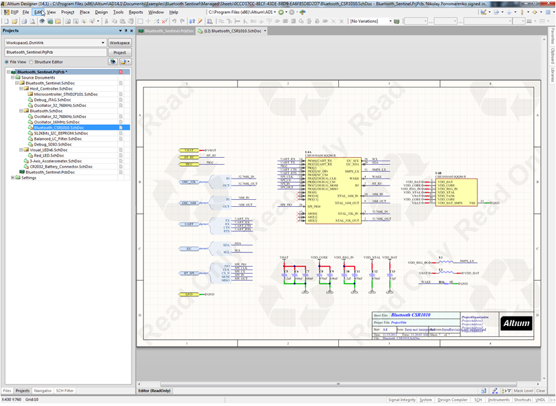
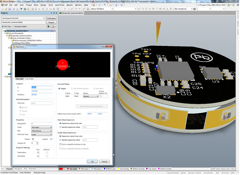
You can imagine any screen-shot of the system window with the loaded scheme. Is this a typical object CAD window? Main working graphic field, toolbar, object property editor? Or are there some features?
Basically, the work is carried out with the logical scheme of the project (the first screenshot) and its physical implementation (the second screenshot). There are certainly many other areas, but these are key.
In the second screenshot (below) - a 3D representation of a flexible-rigid board. The design itself is usually conducted in 2D mode.
Did you use standard Delphi components or did you use additional libraries to increase the level of ergonomics of the interface?
From visual - DevExpress and DreamControls components are quite widely used, there are quite a few self-written controls.
drawing model - used the “outline” or some GPU-based library (OpenGL, DirectX)?
Now for circuits - GDI / GDI +, for PCB - DirectX.
How open is the system? Can I create my own custom plugins?
It was quite open earlier, now there are quite a few extensions, most often of an integration nature. And in recent versions this has been emphasized - we have an SDK for Delphi, C ++ and C #. In the coming days, there is a version of DeveloperEdition, which will make the development of extensions even easier.
Is there a custom automation mechanism? Any scripts, macros, internal programming language?
Yes, there is, quite popular with users, Delphi / Basic / Java-script . It is used both for writing extensions and for everyday work, in particular, for defining complex filters by objects.
Let's talk about the history of development. How did the project start?
The company, like the product, began a long time ago, in the 85th year when available personal computers appeared and there was a need to automate the creation of printed circuit boards. One of the first company created ECAD under Windows, then it was not such an obvious step as it seems now. Next was access to the Australian stock exchange, a series of acquisitions of companies and technologies, building an integrated stack of technologies for the development of electronic devices.
From which version of Delphi and for what is the development of Altium Designere? It is clear that such a large-scale project is difficult to migrate, but have there been successful attempts?
If I'm not mistaken, the first versions of the product were created on TurboPascal, then a series of Delphi versions starting from the 3rd. At the moment, this is Delphi 2010. Migrations usually occurred when it was justified from a pragmatic point of view - the necessary technologies appeared, critical errors were corrected. Any, even a minor modification of the backbone classes makes you think hard and very carefully approach the decision, up to a very accurate calculation of labor costs. We take into account that there are also third-party libraries. While we are not in a hurry with the transition to the latest version.
But besides Delphi uses quite a lot of languages and environments, for example, some of the modules are implemented in C ++ and C #, Morfik is used for some web services and applications.
How is the architecture of the core modules organized? Are these classic versions of the "form-control-action-response-procedure" type or are there more sophisticated techniques such as separation of the model and interface?
In such a large project there are many approaches. One of the key is the separation of the description of commands and the code of their executing. The main command bars and menus are described in external, configurable files, for documents there is a more or less clear separation of the model and the display, the auxiliary isolated dialogs are usually implemented with a classic event form.
Is the interface of the environment basically static or is there a dynamic mechanism for generating a user interface depending on the external configuration?
Part of the interface depends on which document is open (for example, for PCB and BOM, the set of commands and menus is radically different), and what functionality is available with an active license. Those. some basic framework provided by the platform is unchanged, the rest is determined by the mode and logic of the module.
What complex, scientific, with elements of artificial intelligence or just interesting algorithms are used in the system?
Not quite sure about the use of AI, but there are several areas in which the algorithmic framework is quite complicated, especially in the field of PCB and simulation. For example, automatic layout of boards - the area is very capacious in terms of algorithmic. When implementing it, it is necessary to solve not only the task of placing tracks in space (now most boards are multi-layered, and the track can change layers), but also take into account the enormous number of user-defined constraints - the minimum distance between tracks, track impedance, the “noise” of the resulting topology at high frequencies, etc ... This area has not been fully resolved yet.
Are there opportunities to optimize, for example, the overall size of printed circuit boards and structural elements? Multi-parameter optimization? Dynamic constraint setting?
Frankly, I don’t particularly remember any optimizations, especially in size. I would even say that the dimensions often come “outside” - in the form of a specification, a mechanical model of an existing device, the size of the chip used, an interface connector, etc.
Very often, a project can begin with the assignment of a set of restrictions constraint driven desing. The engineer determines the restrictions, sometimes quite complex, and the product helps them to comply or prohibits breaking. For example, one of the simple checks is the width of the track between certain components or the allowable angles when setting up the RF paths.
What are the possibilities for connecting external production equipment to the system? Is it possible to use the system as part of a stand, when an engineer submits a formal description of the task to the input, and a ready-made scheme implemented “in hardware” at the output?
Production - no more than yes. This is still an area, though adjacent, but far from that on which we focus - design and development. It is rather difficult to control the modern assembly line when the automaton applies solder to the finished boards, places the components, and then bakes the board according to the technical process, and does not intersect with the development of the board itself. Although there is certainly support for the manufacturing stage, this is one of the most important parts of the process - the export and preparation of data for the manufacture of boards, for assembly production, for test benches, etc.
From the connected equipment, mention can be made of the Nanoboard , a device used for development using programmable logic (FPGA / FPGA).
Have you thought about the implementation of a mobile front-end? It is known that for many CAD-systems there are already mobile versions of client workstations. Their usefulness is not yet sufficiently obvious, but perhaps you have your own vision of the applicability of mobile applications within large CAD systems or even CAD systems?
Currently there are no such plans. As you yourself noticed, the purpose and necessity of them is not entirely clear. To use them especially, it will not work, as replacing paper drawings in MCAD is also ...
There are mobile development departments in the company, but this is a separate area in the neighboring area that is not directly related to AD.
I can assume that you have a very developed object structure. Do you use graphical notation for interaction between developers? Or is the qualification of programmers such that the existing distribution by areas of responsibility and functionality of the modules allows the source code to use a single source of knowledge about the system?
No, graphic notation is not used. As practice shows, in our case, more effective is direct communication and a sufficient level of development skills.
The more complex the system, the more stringent the requirements for testing, especially regression. How is your process? Automatic tests, manual tests, the ratio between developers and testers?
Although we also have automatic testing covering key areas, manual regression testing, advanced beta testing, in my opinion, testing is one of the areas in which we could improve the situation. For example, one of the problems that we are trying to solve now is the involvement of QA engineers in the early stages of development.
What is the personnel policy of Altium? Do you have a fairly closed team? Or are you always open and ready to hire a decent specialist?
In this area, the company is more than open. As far as I know, at the moment we are actively looking for developers of high qualification in the Kiev and Shanghai offices. By the way, a funny moment - it turned out that a significant part of the core of the R & D of our Australian company is now made up of Russian-speaking engineers.
First of all, you are expanding the staff at the expense of professionals or there are vacancies for beginners who are just starting to build their career in software development?
Usually, developers come to the company either with good skills and experience or possessing any unique competencies. Beginners to join the rhythm and the task is quite difficult.
If you invite unique specialists with knowledge, skills and experience, are you ready to pay salaries above the market average?
Yes :).
Nevertheless, Altium is a grocery company, and a lot depends on who works on the product. Here we will not discuss the formal aspects of the issue, for this there are special people in our company (anastasia.demchenko@altium.com), they are always in touch.
To work in Altium as a developer, what do you need to know besides Delphi? Need to be an “electronic engineer” born with a “soldering iron in your hands”? Or do you need to know mathematics and CAD theory very well? Or just need to be a competent programmer with good experience in solving various problems?
No, it’s not necessary to work in our company, it was necessary to be born “with a soldering iron in hands” :)) Certainly, knowledge of electronics or mathematics for some areas is a plus, but not an obligatory requirement - the range of tasks we face is very wide.
What is the development strategy of the product part? What is a priority now? Increasing the level of automation? Functional extensions? An attempt to enter adjacent areas, for example, designing other elements of complex technical systems?
There are several areas, mainly they are aimed at expanding their market share in ECAD systems. Those. we are unlikely to move in the direction of mechanical CAD, except for expanding integration with existing products, but we will certainly improve, for example, the design capabilities of boards in 3D.
The traditional question. What can advise novice programmers who want to grow to the level of professional development, to be, for example, claimed by Altium?
The answer is generally universal here - to gain experience, learn to solve problems, have a good technical base. There are several open ECAD projects , participation in them can be very useful.
Source: https://habr.com/ru/post/205974/
All Articles