You are not programming microcontrollers yet? Then we go to you!
 Hello, dear Habrazhiteli!
In this article I want to talk about how once I decided to start programming microcontrollers, what was needed for this and what happened in the end.
I was interested in the topic of microcontrollers for a very long time, in the year 2001. But then it turned out to be problematic to get a programmer at the place of residence, and there was no question of buying via the Internet. I had to postpone this thing until better times. And so, one day I discovered that the
1. Programmer
There are many options on the market - from the cheapest ISP (In-System Programming) programmers for a few dollars, to powerful programmers-debuggers for a couple of hundred. Not having much experience in this matter, for a start I decided to try one of the simplest and cheapest - USBasp. I bought at one time on eBay for $ 12, now you can even find it for $ 3-4. This is actually the Chinese version of the Thomas Fischl programmer. What can I say about him? Only one thing - it works. In addition, it supports a lot of AVR controllers of the ATmega and ATtiny series. Under Linux does not require a driver.
')

For firmware, connect the outputs of the
VCC, GND, RESET, SCK, MOSI, MISO programmer to the corresponding outputs of the microcontroller. For simplicity, I put together an auxiliary circuit right on the breadboard: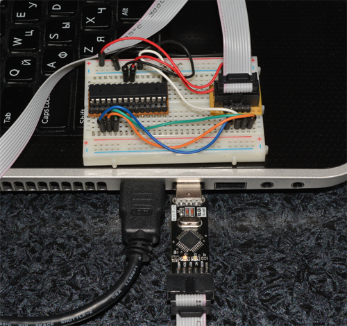
On the left on the board is the same microcontroller that we are going to flash.
2. Microcontroller
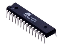
With the choice of a microcontroller, I didn’t really bother and took the Atmega8 ATmega8 - 23 I / O pins, two 8-bit timers, one 16-bit, frequency up to 16 MHz, low consumption (1-3.6 mA), cheap ($ 2). In general, for the beginning - more than enough.
Under Linux, the avr-gcc + avrdude bundle works perfectly for compiling and downloading firmware to the controller. Installation is trivial. Following the instructions , you can install all the necessary software in a few minutes. The only nuance to which attention should be paid is that avrdude (software for writing to the controller) may require super user rights to access the programmer. Exit - run through sudo (not a good idea), or prescribe special udev rights. The syntax may differ in different versions of the OS, but in my case (Linux Mint 15), the following rule was added to the
/etc/udev/rules.d/41-atmega.rules file: # USBasp programmer SUBSYSTEM=="usb", ATTR{idVendor}=="16c0", ATTR{idProduct}=="05dc", GROUP="plugdev", MODE="0666" After this, of course, you need to restart the service.
service udev restart Compiling and flashing without problems can be directly from the command line (who would doubt), but if there are many projects, it is more convenient to install the AVR Eclipse plugin and do everything directly from the Eclipse environment.
Under Windows you have to install the driver. The rest is no problem. For the sake of scientific interest I tried a bunch of AVR Studio + eXtreme Burner in Windows. Again, everything works out with a bang.
We start to program
AVR controllers can be programmed either in assembler (AVR assembler) or in C. Here, I think everyone should make their own choice, depending on the specific task and their preferences. Personally, I first started picking assembler. When programming in assembler, the device architecture becomes clearer and you get the feeling that you are digging directly into the inside of the controller. In addition, I believe that knowledge of the assembler can be very useful in programs that are especially critical in size and performance. After getting acquainted with the AVR assembler, I crawled on to C.
After becoming acquainted with the architecture and basic principles, I decided to collect something useful and interesting. Then my daughter helped me, she was engaged in chess, and one fine evening she declared that she wanted to have a clock-timer for parties for a while. Bam! Here it is - the idea of the first project! You could certainly order them on the same eBay, but I wanted to make my own watches, with black ... uh ... with indicators and buttons. No sooner said than done!
As a display, it was decided to use two 7-segment diode indicators. 5 buttons were enough for control -
“ 1” , “ 2” , “” , “” and “” . Well, do not forget about the sound indication of the end of the game. Look like that's it. The figure below shows the general scheme of connecting the microcontroller to the indicators and buttons. We will need it when parsing the program source code:
Debriefing flight
Let's begin, as it should be, from the entry point of the program - the
main function. In fact, there is nothing remarkable in it — setting up ports, initializing data, and an endless loop of handling keystrokes. Well, the call to sei() is the resolution of interrupt handling, about them a little later. int main(void) { init_io(); init_data(); sound_off(); sei(); while(1) { handle_buttons(); } return 0; } Consider each function separately.
void init_io() { // set output DDRB = 0xFF; DDRD = 0xFF; // set input DDRC = 0b11100000; // pull-up resistors PORTC |= 0b00011111; // timer interrupts TIMSK = (1<<OCIE1A) | (1<<TOIE0); TCCR0 |= (1 << CS01) | (1 << CS00); TCCR1B = (1<<CS12|1<<WGM12); //OCRn = (clock_speed / prescaler) * seconds - 1 OCR1A = (F_CPU / 256) * 1 -1; } Configuring I / O ports is very simple - a number is written to the DDRx register (where x is the letter designating the port), each bit of which means whether the corresponding pin is an input device (corresponds to 0) or an output (corresponds to 1). Thus, by sending the number 0xFF to DDRB and DDRD, we made B and D output ports. Accordingly, the
DDRC = 0b11100000; command DDRC = 0b11100000; turns the first 5 pins of port C into the input pins, and the rest on the weekend. Team PORTC |= 0b00011111; includes internal pull-up resistors at 5 controller inputs. According to the diagram, buttons are connected to these inputs, which, when pressed, close them to the ground. Thus, the controller understands that the button is pressed.The following is the setting of two timers, Timer0 and Timer1. We use the first one to update the indicators, and the second one to count down the time, having previously configured it to operate every second. A detailed description of all the constants and the method of setting the timer for a specific interval can be found in the documentation for ATmega8.
Interrupt handling
ISR (TIMER0_OVF_vect) { display(); if (_buzzer > 0) { _buzzer--; if (_buzzer == 0) sound_off(); } } ISR(TIMER1_COMPA_vect) { if (ActiveTimer == 1 && Timer1 > 0) { Timer1--; if (Timer1 == 0) process_timeoff(); } if (ActiveTimer == 2 && Timer2 > 0) { Timer2--; if (Timer2 == 0) process_timeoff(); } } When the timer is triggered, control is transferred to the corresponding interrupt handler. In our case, this is the TIMER0_OVF_vect handler, which calls the procedure for outputting time to the indicators, and TIMER1_COMPA_vect, which handles the countdown.
Conclusion on indicators
void display() { display_number((Timer1/60)/10, 0b00001000); _delay_ms(0.25); display_number((Timer1/60)%10, 0b00000100); _delay_ms(0.25); display_number((Timer1%60)/10, 0b00000010); _delay_ms(0.25); display_number((Timer1%60)%10, 0b00000001); _delay_ms(0.25); display_number((Timer2/60)/10, 0b10000000); _delay_ms(0.25); display_number((Timer2/60)%10, 0b01000000); _delay_ms(0.25); display_number((Timer2%60)/10, 0b00100000); _delay_ms(0.25); display_number((Timer2%60)%10, 0b00010000); _delay_ms(0.25); PORTD = 0; } void display_number(int number, int mask) { PORTB = number_mask(number); PORTD = mask; } The
display function uses the dynamic display method. The fact is that each individual indicator has 9 contacts (7 for controlling segments, 1 for a point and 1 for power). To manage 4 digits would need 36 contacts. Too wasteful. Therefore, the output of digits to the indicator with several numbers is organized according to the following principle: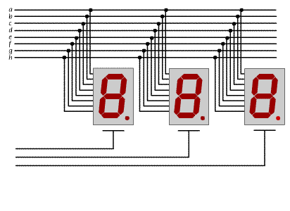
The voltage is alternately applied to each of the common contacts, which allows you to highlight the desired number on the corresponding indicator using the same 8 control contacts. At a sufficiently high output frequency, this looks to the eye as a static picture. That is why all 8 power contacts of both indicators in the diagram are connected to 8 outputs of port D, and 16 control segments of contacts are connected in pairs and connected to 8 outputs of port B. Thus, the display function with a delay of 0.25 ms alternately outputs the required figure to each of the indicators . At the end, all outputs that energize the indicators are disabled (command
PORTD = 0; ). If this is not done, the last displayed digit will continue to be lit until the next call to the display function, which will result in a brighter glow than the others.Click processing
void handle_buttons() { handle_button(KEY_SETUP); handle_button(KEY_RESET); handle_button(KEY_PAUSE); handle_button(KEY_PLAYER1); handle_button(KEY_PLAYER2); } void handle_button(int key) { int bit; switch (key) { case KEY_SETUP: bit = SETUP_BIT; break; case KEY_RESET: bit = RESET_BIT; break; case KEY_PAUSE: bit = PAUSE_BIT; break; case KEY_PLAYER1: bit = PLAYER1_BIT; break; case KEY_PLAYER2: bit = PLAYER2_BIT; break; default: return; } if (bit_is_clear(BUTTON_PIN, bit)) { if (_pressed == 0) { _delay_ms(DEBOUNCE_TIME); if (bit_is_clear(BUTTON_PIN, bit)) { _pressed |= key; // key action switch (key) { case KEY_SETUP: process_setup(); break; case KEY_RESET: process_reset(); break; case KEY_PAUSE: process_pause(); break; case KEY_PLAYER1: process_player1(); break; case KEY_PLAYER2: process_player2(); break; } sound_on(15); } } } else { _pressed &= ~key; } } This function in turn polls all 5 buttons and handles pressing if one happens. The
bit_is_clear(BUTTON_PIN, bit) registered by checking bit_is_clear(BUTTON_PIN, bit) , i.e. a button is pressed if its corresponding input is connected to ground, which is what will happen, according to the diagram, when the button is pressed. The delay of the DEBOUNCE_TIME duration and the re-check is needed to avoid multiple unnecessary operations due to contact bounce. Storing the pressing status in the corresponding bits of the _pressed variable _pressed used to prevent repeated operation when the button is pressed for a long time.The functions of processing clicks are quite trivial and I suppose that they do not need additional comments.
Full text of the program
#define F_CPU 4000000UL #include <avr/io.h> #include <util/delay.h> #include <avr/interrupt.h> #define DEBOUNCE_TIME 20 #define BUTTON_PIN PINC #define SETUP_BIT PC0 #define RESET_BIT PC1 #define PAUSE_BIT PC2 #define PLAYER1_BIT PC3 #define PLAYER2_BIT PC4 #define KEY_SETUP 0b00000001 #define KEY_RESET 0b00000010 #define KEY_PAUSE 0b00000100 #define KEY_PLAYER1 0b00001000 #define KEY_PLAYER2 0b00010000 volatile int ActiveTimer = 0; volatile int Timer1 = 0; volatile int Timer2 = 0; volatile int _buzzer = 0; volatile int _pressed = 0; // function declarations void init_io(); void init_data(); int number_mask(int num); void handle_buttons(); void handle_button(int key); void process_setup(); void process_reset(); void process_pause(); void process_timeoff(); void process_player1(); void process_player2(); void display(); void display_number(int mask, int number); void sound_on(int interval); void sound_off(); // interrupts ISR (TIMER0_OVF_vect) { display(); if (_buzzer > 0) { _buzzer--; if (_buzzer == 0) sound_off(); } } ISR(TIMER1_COMPA_vect) { if (ActiveTimer == 1 && Timer1 > 0) { Timer1--; if (Timer1 == 0) process_timeoff(); } if (ActiveTimer == 2 && Timer2 > 0) { Timer2--; if (Timer2 == 0) process_timeoff(); } } int main(void) { init_io(); init_data(); sound_off(); sei(); while(1) { handle_buttons(); } return 0; } void init_io() { // set output DDRB = 0xFF; DDRD = 0xFF; // set input DDRC = 0b11100000; // pull-up resistors PORTC |= 0b00011111; // timer interrupts TIMSK = (1<<OCIE1A) | (1<<TOIE0); TCCR0 |= (1 << CS01) | (1 << CS00); TCCR1B = (1<<CS12|1<<WGM12); //OCRn = (clock_speed / prescaler) * seconds - 1 OCR1A = (F_CPU / 256) * 1 -1; } void init_data() { Timer1 = 0; Timer2 = 0; ActiveTimer = 0; } int number_mask(int num) { switch (num) { case 0 : return 0xC0; case 1 : return 0xF9; case 2 : return 0xA4; case 3 : return 0xB0; case 4 : return 0x99; case 5 : return 0x92; case 6 : return 0x82; case 7 : return 0xF8; case 8 : return 0x80; case 9 : return 0x90; }; return 0; } void process_setup() { Timer1 += 60; Timer2 += 60; // overflow check (5940 seconds == 99 minutes) if (Timer1 > 5940 || Timer2 > 5940) { Timer1 = 0; Timer2 = 0; } } void process_reset() { init_data(); } void process_timeoff() { init_data(); sound_on(30); } void process_pause() { ActiveTimer = 0; } void process_player1() { ActiveTimer = 2; } void process_player2() { ActiveTimer = 1; } void handle_button(int key) { int bit; switch (key) { case KEY_SETUP: bit = SETUP_BIT; break; case KEY_RESET: bit = RESET_BIT; break; case KEY_PAUSE: bit = PAUSE_BIT; break; case KEY_PLAYER1: bit = PLAYER1_BIT; break; case KEY_PLAYER2: bit = PLAYER2_BIT; break; default: return; } if (bit_is_clear(BUTTON_PIN, bit)) { if (_pressed == 0) { _delay_ms(DEBOUNCE_TIME); if (bit_is_clear(BUTTON_PIN, bit)) { _pressed |= key; // key action switch (key) { case KEY_SETUP: process_setup(); break; case KEY_RESET: process_reset(); break; case KEY_PAUSE: process_pause(); break; case KEY_PLAYER1: process_player1(); break; case KEY_PLAYER2: process_player2(); break; } sound_on(15); } } } else { _pressed &= ~key; } } void handle_buttons() { handle_button(KEY_SETUP); handle_button(KEY_RESET); handle_button(KEY_PAUSE); handle_button(KEY_PLAYER1); handle_button(KEY_PLAYER2); } void display() { display_number((Timer1/60)/10, 0b00001000); _delay_ms(0.25); display_number((Timer1/60)%10, 0b00000100); _delay_ms(0.25); display_number((Timer1%60)/10, 0b00000010); _delay_ms(0.25); display_number((Timer1%60)%10, 0b00000001); _delay_ms(0.25); display_number((Timer2/60)/10, 0b10000000); _delay_ms(0.25); display_number((Timer2/60)%10, 0b01000000); _delay_ms(0.25); display_number((Timer2%60)/10, 0b00100000); _delay_ms(0.25); display_number((Timer2%60)%10, 0b00010000); _delay_ms(0.25); PORTD = 0; } void display_number(int number, int mask) { PORTB = number_mask(number); PORTD = mask; } void sound_on(int interval) { _buzzer = interval; // put buzzer pin high PORTC |= 0b00100000; } void sound_off() { // put buzzer pin low PORTC &= ~0b00100000; } The prototype was assembled on a breadboard:

After testing the prototype, it's time to put all this stuff in the case, provide power, etc.

Below is the final view of the device. The clock is powered by a 9 volt “Krona” type battery. Current consumption - 55 mA.

Conclusion
Having spent $ 20-25 on equipment and a couple of evenings on the initial acquaintance with the microcontroller architecture and basic principles of work, you can start doing interesting DIY projects. The article is dedicated to those who, like me at one time, think that it is difficult, long or expensive to start programming microcontrollers. Believe me, starting is a lot easier than it sounds. If there is interest and desire - try, you will not regret!
Good luck to all programming!
PS And finally, a small video demonstration of the prototype:
Source: https://habr.com/ru/post/205972/
All Articles