How did the Tesla Power Transmission Tower work - its own “investigation”
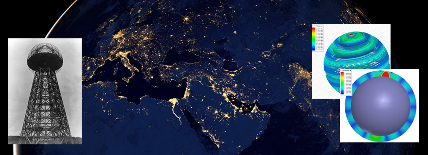
A few years ago, we - the authors of this material - after digging into N. Tesla's patents, diaries and lectures (good, education allowed), came to the conclusion that the notorious Tesla Tower for energy transfer was not a “fake”, but a completely working design.
As a result of several years of research, reflection, study of primary sources, comparison of data, formation and elimination of hypotheses, etc. - there was a beautiful and, in fact, a simple model that strictly fit into classical physics and was confirmed by numerical simulation in the Ansoft HFSS package. Since the start of the project, we have held a number of discussions in various communities, where we were asked to “article for techies” - as a result, this material appeared.
')
This material is not a strict theory (that is, a theory that takes into account all possible aspects of the operation of the Tesla Tower). Nevertheless, we tried to sufficiently fully illuminate the proposed concept and provide adequate numerical estimates of the main characteristics of the process. So, if you are interested in understanding the model and participating in a constructive discussion, we invite you to read the materials.
So, in our scientific-pop article, the beginning of the concept is stated - in fact, the starting point of research (the formulation of which, by the way, took a fair amount of time).
It is possible in several sentences to describe the essence of the post below, with the note "attention is not for specialists." Then the essence could be formulated as follows: the Tower creates a resonance of current – voltage in a long line, where the entire Earth is taken as a long line (conductor, connected to the master oscillator at one end, ie to the Tower). Earth’s resistance turns out to be tiny (why - disassembled below). Losses from EM radiation also do not have dramatic consequences, since “Rescues” the ionosphere, from which low-frequency electromagnetic radiation is perfectly reflected, and, having reflected, interacts with the Earth, again passing into currents in a long line — the Earth (waveguide model). And a stable picture of standing currents – voltages – charges waves in the earth appears, accompanied by weak EM – radiation between the earth and the ionosphere.
We began with the fact that we thoroughly studied the mode of operation of the Tesla Tower following its notes and patents. And from this an understanding has already been born - what kind of physical processes such a device can cause in planet Earth, and from this understanding - there is a certainty that the transfer of energy by the proposed (and approved) Tesla path is quite possible. At the same time, we start from the fact that Tesla's patent contains the entirety of the description and there are no “hidden / hidden” parameters / processes. So, the “ideas” actively exaggerated by the yellow press and the media - that Tesla, with the help of his Tower, tried to “pump the energy of the ether”, use “radiant energy”, etc. - we believe are only fantasies of journalists, far from physics. In our opinion, the work of the Tower is completely within the known physical laws, does not require the involvement of any new concepts or physical effects, and in this sense our work (and the future planned experiment) is of a purely applied nature - and not the nature of basic research. If the material below is difficult to understand, then you can read the article at the link above (it is written for the humanities, and contains a number of inaccuracies bordering on incorrectness, but gives a good qualitative understanding).
Behind this, let's get started.
Tesla Tower: performance

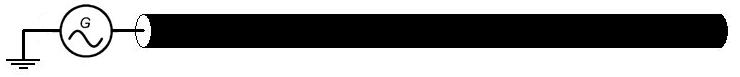
If you cut off all that is impossible, then the Tesla Tower (minus the technical nuances that are not significant here) is nothing more than a spiral quarter-wave resonator grounded at one end (characterized by distributed parameters), with an additional capacity at the upper end of the spiral. This resonator is swung by a master oscillator (sinusoidal signal, frequency below 20 kHz - if we start from Tesla patents US787412 and US1119732 ).
In other words, the circuit diagram of the tower is as follows:

The left shows the physical solitary capacity at the top of the tower (additional to the coil's own capacity), the right shows the conventional equivalent circuit, where it is emphasized that the capacity is solitary, i.e. formally - the capacity between the Tower and infinity, and not between the Tower and the Earth (because otherwise we get a banal LC-circuit, closed through the ground). In order to minimize the parasitic capacitance between the tower and the ground - i.e. closure of the LC circuit of the Tower through the ground - obviously, it is necessary to raise the solitary capacity from the ground (a simple estimate shows that it is enough to raise the capacity to a height equal to several average diameters of such a capacity - if this condition is fulfilled, the capacity between the Tower and the Earth will decrease to a value comparable to own lonely capacity of the Tower).
As is known from classical electrical engineering, in the resonance mode of such a resonator, the capacitive and inductive resistances mutually compensate each other, so that the generator “sees” only the active resistance of the resonator. In the helix, a standing wave arises - with a voltage node at the generator point, and with an antinode of current there (at the end of the cavity, on the contrary, the voltage antinode and current node). A detailed analytical theory of the operation of such a resonator can be viewed, for example , here . If the material on this link is difficult to understand - it can be simplified without losing the essence: a spiral resonator of this kind is nothing more than just a quarter-wave long line rolled into a spiral - that is, as in the “stretched” line length, in such a resonator at the resonant frequency there will be a standing wave of current-voltage, with a voltage node at one end of the line, and a current node at the opposite end of the line; a significant difference from the “elongated” long line - only in the enhanced inductive and capacitive coupling between adjacent sections of such a line due to their geometric proximity in a spiral configuration, which slightly (not several times) - changes the resonant frequency and velocity of wave propagation along the line.

In the figure - standing waves in a long line. Wave distribution: a - voltage; b - current in a single-conductor line at different points in time (illustration from the site )
In other words, the Tower is a charge buffer — a solitary capacitance into which the master power generator “drives” a charge from the ground.
At the same time, EM radiation in the sense of radio waves (ie, the field in the far, wave zone of the Tower) is practically absent for our range of operating parameters. Show it.
In radio physics, there is the concept of spiral antennas, which, at first glance, can be correlated with such a spiral resonator. However, unlike antennas, the electrical length of a tower's turn is 3-5 orders of magnitude shorter than the wavelength (i.e., the number of turns is in the thousands, while the entire length of the winding is approximately equal to a quarter of the wavelength). At the same time, most of the currents (current antinodes) are concentrated in the lower half of the tower. In other words, in the sense of external EM radiation, such a structure works like a conventional classical concentrated inductance . Those. ordinary magnetic dipole.
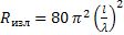
A known formula specifies the radiation resistance of an electrically short magnetic frame (magnetic dipole) with a wavelength λ ( the radiation resistance characterizes the loss of a conductor due to the emission of electromagnetic waves - that is, the loss of current energy to radiation is considered as a formal resistance, the losses of which are equal to losses on radiation):
 (formula 4.30 by reference above)
Where the equivalent length of the dipole l e associated with the radius "a" of the framework:

For the case of N turns, the formula is multiplied by the N 2 coefficient (for obvious reasons, the radiation energy density is proportional to the square of the amplitude of the field of the frame, that is, to the square of the number of turns in the frame).
Total
Substituting our parameters (frequency 10 kHz, i.e., wavelength 30,000 m, coil radius - let it be 2 meters, winding length - 10 km, number of turns about 800), we obtain radiation resistance equal to 390 nano. That is negligible compared to the losses on the active resistance of the system (at least a unit Ohm).
But, in addition to the tangential component of the current in such a resonator, there is also an axial component (the resulting vertical current) due to which the Tower gives, among other things, the radiation of an ordinary short electric dipole, for which the radiation resistance is related to the dipole length l and the wavelength λ as:
 (formula 4.27 at the link above)
Thus, the radiation resistance (relative to the current flowing through the generator) for the vertical component of the current and for our parameters (tower height of tens of meters - let it be 30 meters for concrete, and frequencies of 10 kHz) can be estimated at about 1 milliohm.
As a result, we see that both types of radiation (both from the tangential and axial components of the current) are negligible relative to the losses on the active resistance of the circuit, while these are estimates from above (since for them the current value is the same throughout the coil winding , while in fact the current drops along the sine - and at the “hot end” of the coil there is a current node - that is, zero current, and the actual radiation will be several times less than the estimates above). So, any ideas that the Tower works as an antenna have absolutely no basis for it (at least, as long as we follow Tesla's patents, rather than do fantasizing). The tower is not an antenna in the classical sense - its radio emission (those EM field in the far wave zone) is negligible, and all it can do is to be an effective accumulator for the charge that the generator drives and removes from the soil at the frequency of the generator . So, “brilliant” objections of the form “you have an ordinary spiral antenna - the efficiency of energy transfer will be below the plinth”, and other “arguments” emanating from the radio emission of such a structure only demonstrate a complete misunderstanding by the opponent of the most basic concepts of radiophysics.
With the Tower figured out, now we go to Earth
For simplicity, let's start with elementary analogies - from which we will gradually move on to the final concept.
Suppose we have an electrically-long conductor with a gap at one end, grounded by the second end through an alternating voltage source (electrically long - means that the conductor length is comparable / greater than the wavelength from the generator, based on the generator frequency and the wave propagation speed - close to light in vacuum):
In such a long line, if the losses in the line are small, a standing current-voltage wave occurs (i.e., a superposition of the incident waves from the generator and the waves reflected from the free end of the long line). A typical example of such lines and such waves are ordinary electric vibrators (I mean classical antennas), as shown in the figure below.
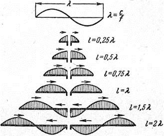 Current distribution in symmetric vibrators of various lengths.
The essence of standing waves in a long line is simple enough to understand. You can mentally break the entire conductor into segments in half the wavelength. Each such segment is a capacitance (since the conductor has a capacitance distributed along it) and inductance (similarly). Accordingly, standing waves are nothing more than waves of currents charging such capacitances - i.e. the energy in such a standing wave alternately accumulates in the form of charge distributed along the conductor (sine) - and at this moment the currents are zero, then in the form of currents distributed along the conductor (also sine) - and at this moment the surface charge density along conductor is zero. What essentially repeats the mode of operation of a conventional LC circuit (inductor in series connected to a capacitor-capacitor), but only taking into account the distributed nature of capacitance and inductance. The currents in the half-wave “flow” to the center of such a selected segment - creating an antinode voltage (ie, the appearance of a surface charge on the conductor), and in the next segment “spread” from a similar center - creating a charge of opposite sign, then this process repeats (in the opposite direction). side - creating opposite charges on the surface of the conductor). Of course, the above refers to the ideal line (lossless) open at the end, in a real line with losses (and / or lines with a load at the end) the processes are somewhat more complicated - but the fundamental essence does not change.
If we move to elementary mechanical analogies, the closest process will be compression-tension waves in a long spring, arising in the case when such a spring (lying on a support with zero friction) begins to swing back and forth along the spring axis at one of the spring ends - with anchored to the second end. In this case, the current corresponds to the speed of movement of the corresponding section of the spring, and the voltage corresponds to the degree of compression of the spring. Those. at some point in time, all sections of the spring will have zero speed — and the degree of stretching of the spring will vary along the sine along it (such alternating bunches and discharges) —which corresponds to zero current in the standing wave and at the same time maximum voltage (i.e. maximum surface charge density on the conductor), and at another point in time - after a quarter of the oscillation period - on the contrary, the whole spring will not be deformed, but the instantaneous speed of its sections will vary along a sine along the axis of the spring (which corresponds to m ment zero charge density along the length of the conductor line - but a current peak therein).
Losses for such a situation as a whole can be divided into 2 components: ohmic losses, and radiation losses.
In the case of a large conductor length, and its low ohmic resistance, the main contribution to the loss will be radiation (i.e. radiation resistance).
As you know, if you surround such a line with a grounded conductive screen, then the radiation losses will be leveled, and this structure is called a coaxial waveguide - and, in our example, a wave in such a coaxial waveguide will exist as a TEM mode (the excitation port will in essence, is a generator connected through the ground - to the inner and outer conductors of the waveguide).
In fact, the TEM-mode mode can be interpreted as the mode of inductive coupling of the inner and outer conductors of the waveguide through the near-field field of the currents on these conductors (a change in current on the inner core causes an emf on the outer screen, respectively, and the current induced on the outer screen is directed against current on the inner core - that is, in fact, the usual induction in the near field of the current), so that the transverse energy fluxes are not just zero on average in time (as for the TE or TM mod), but zero at any given time. There are no re-reflections from the waveguide boundaries - the energy flow is only longitudinal in nature (ie, directed along the axis, and accordingly the Poynting vector is directed just strictly parallel to the direction of wave propagation — along the axis of such a coaxial resonator).
Therefore, the TEM mode in a coaxial waveguide is characterized by good parameters (relative to TE or TM modes) in terms of energy transfer and in part of the small attenuation coefficient of the wave in the waveguide, and if necessary, energy transfer through the coaxial waveguide is usually used -modes
However, even if we remove the grounding of the external screen of such a waveguide, along the entire length of the screen, except for its end sections, the screen will perfectly perform its function.
After all, such a screen in any case is a long line, the quality of the generator for which is the emf from the alternating current on the internal core conductor. And only at the edges of the screen - due to the very small capacity of such edges, there will be some antinode of voltage, and throughout the rest of the length of such a screen - it will function normally. That is confirmed by elementary modeling in HFSS.
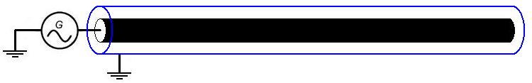
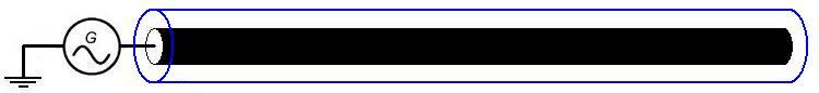
Further, what happens if we do not just remove the grounding of the external screen - but “close” the edges as shown in the figure below (so that the external screen becomes a kind of “capsule”)? The answer is quite clear - this situation will not differ from the one discussed above. The screen will work along the entire length, and at such terminations of the outer “capsule” there will be antinodes of voltages (and current nodes, respectively).
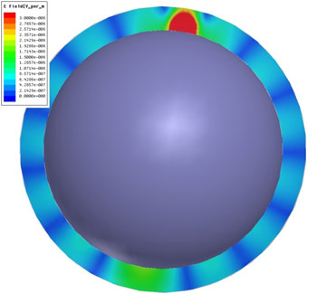
Further, if the inner and outer conductors are already made in the form of spheres, then we will come to the general model of the intended experiment (the proportions in the figure, of course, are not met):

As it is not difficult to guess, the inner conducting sphere is the Earth, the outer conducting sphere is the upper layers of the atmosphere (mainly the ionosphere). And the general geometry of such a resonator is a usual concentric spherical resonator (in which it is already impossible to speak about TEM fashion, in the strict sense, since only the TE and TM modes exist in it), only with a slightly unusual way of exciting the TM mode ( ie, the port of excitation - does not connect the outer and inner plates together, as is done in the "classical" electrical engineering).
Although, due to the variable cross section of the inner and outer conductors, the amplitudes of the standing waves of currents and voltages will decrease with distance from the generator, the overall essence remains the same - the TEM mode of the coaxial (or TM-mode of the spherical) resonator excited by the corresponding source (Tesla Tower).
At first glance, the idea is strange: it is known that the conductivity of the soil of the Earth and the ionosphere (on a clear day on the illuminated side) is about 0.001 S / m (plus or minus order), while the conductivity of eg copper is about 58,000,000 S / m However, let's look at this question based on numerical estimates, and not from intuitive considerations. And first, let's deal with the resistance of the earth’s soil. The general idea is that from the point of view of current flow processes, the division into dielectrics, semiconductors and conductors is rather arbitrary in nature, since at a sufficiently large dielectric section, it becomes a quite good conductor (i.e., it has a low total resistance).
As you know, with sufficient thickness of the conductor, the current is essential only at a certain depth, called the depth of the skin layer, which is calculated by the formula :

Where
 - resistivity,
  - relative magnetic permeability,
  - frequency.
Of course, this is a simplified formula that is applicable to a conductor, not a dielectric — however, at our ultra-low frequencies, the losses associated with the dielectric constant of the soil are small, so as an estimate, such a formula is quite applicable.
For the frequency range of 1–10 kHz, and the conductivity range of 0.001–0.00001 S / m, the depth of the skin layer lies in the range from hundreds of meters to several kilometers. In this case, the lower the frequency is, the greater is the thickness of the skin layer, i.e. the less ohmic losses in planetary resonance (inversely proportional to the root of the frequency).
Thus, we come to the conclusion that, considering the purely active resistance of the Earth (as a sphere of soil, that is, a material having a conductivity of 0.01-0.0001 S / m), and implying a frequency range not lower than 1 kHz (because . even lower frequencies are not realizable from a practical point of view - on the basis of the required technical parameters of the Tesla Tower) it is necessary to confine ourselves to a kilometer layer. Note that Tesla, apparently, did not quite realize this, and sincerely believed that the currents from its installation go deep into the earth (and do not run along the surface thereof), as indicated in our popular science article. According to modern data on electrodynamics - this, of course, can not be.
The resistance between two rods immersed in a poorly conducting medium (for example, in the ground) is given by the formula :

Where
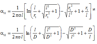
Here L is the length of the rods, D is the distance between them, r1 is the radius of the section of the rods,
 - specific conductivity of the medium.
It is interesting to note that based on this formula, starting from the distance between the rods of a much longer rod length, the resistance between the rods actually becomes constant (ceases to grow as the distance increases).
For example, for two rods with a length of 30 m, a diameter of 0.2 m, and a soil conductivity of about 0.04 S / m (which is correct for the upper soil layers), the characteristic resistance (between them) lies in the range of 1-3 Ohms - starting from a distance of meters, and further (without limiting the distance) it remains so with any increase in the distance between the rods. So the idea that the Earth is a bad conductor (as an object as a whole) is, of course, an intuitive delusion, and if that were so, grounding would simply not make sense.
, – (.. , – -). ( ).

, .
, , -

( , - ) (. ):

R s1 R s2 — , :

– ( – ).
, – .. ( ), – “” . , (f=3 , σ=0.01 / 1.06 ) ( ) , - .
– , , . , (.. - , – ). . D d (D=6 600 000 , d = 6 400 000 ,), , 10 -8 -10 -9 1/.
, ( ) – .. .
10 -9 , «x» ( 20 000 )
 =2%.
=2%.- ( , ) , -. 1-3 ( ) .
, , ( ) , 2-3 ( – ).
- - .. – “ ”.
, - (, , — ).
- – .. . , , – ( 10 – 0-6).
,

– 1.5 , – 3 , ..
, , – “” ( 10 , 10 – 0.01-0.1 ). , - , - /: , . .
. (, . – . 8 ), , – . , - . , (-). , – , – 0.1-1 (. 6-8) . , , (, ) . , - , ( - ), : , , - – , . , - - – : , – , , - () - – .
, - - ( – 2011 ):

, – , (.. , ). “” , – .. , .
, 2011 ( ) ( ) (400-800 ), . -, – - -.
, – , , . ( ) – - /.
( , - ), (.. - ) — .
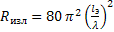
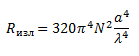
, , , ( — ) : ( ), – “” , HFSS ( - ).

E B 3- - -.
“” -
Where do we get the “grounding” to which the generator is connected to pump such a resonator in the figure above?

– . , ( ). Since “” , , ( – ) — , “” , .
, , – , (.. -). , – “ ” (.. — , - -).
After the establishment of standing stress waves and currents across the planet (currents will have an extremely small amplitude - unlike voltages), this energy can be effectively removed by a similar system (by the Tower - but without a generator). Physical processes during receiver operation are characterized by creating a connection between the resonant circuits (tower-receiver), which allows to obtain high transmission efficiency even with an extremely low coupling coefficient of the source and receiver (strictly in accordance with classical electrical engineering).
Consider this question in more detail.
In the case of the location of the receiver (ie, a similar circuit) in the voltage antinodes (and current node) of the resulting standing wave, the alternating potential of the surface will be the source of emf for the receiver. At the same time, a resonance will be excited in the receiver - completely similar to the resonance at the source, respectively, the receiver will generate a standing wave just as completely as the source. Moreover, since the receiver is located in the voltage antinode (and the current node), the wave generated by it will obviously create an additional load on the source — thereby creating a system in the form of a so-called. resonant coupled circuits (a quick overview on this subject can be found here and here ). Indeed, in the antinodes of the external wave voltage - the receiver has a voltage node (and current antinode), and operates at the same frequency, i.e. in the area of the source location, the receiver will create a voltage antinode (and a current node), which the source will “see” as an additional load. What is perfectly visible on the video (corresponding to the modeling in HFSS).
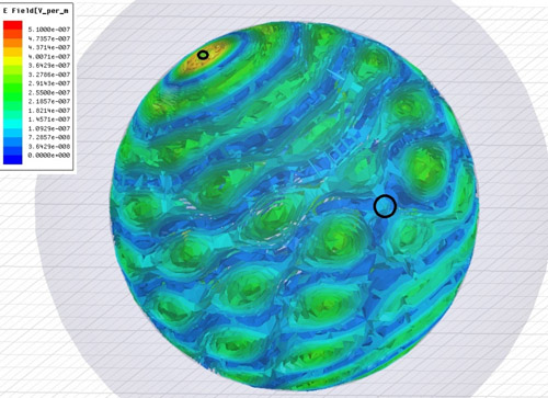
In the video and in the figure above - the source is located in the upper left area, the area of the receiver is highlighted in the right near-central part. It can be seen that in the receiver area a constant minimum of the field - which means efficient pumping of energy from the planetary resonance. The interference pattern of the waves emitted by the receiver and source is also clearly visible.
For systems of this kind (i.e., resonant coupled circuits), the efficiency of energy transfer is determined by the product of the coupling coefficient of the systems k and their quality factor Q. The coupling coefficient is, roughly speaking, the coefficient that determines how much of the resonance energy of the source circuit is “seen” receiver circuit. For example, for closely spaced inductor coils (especially if they are wound on one core), the coupling coefficient tends to unity, and decreases as the coils explode (because as such explodes, the emf drops, induced by the coils in each other). A typical graph of efficiency depending on the product of the coupling coefficient for the good quality is given below (taken from the document by the link above ):

The physical meaning of this dependence is obvious: even if during one oscillation period the receiver “takes” only a small percentage of the source energy, but over the same period (due to the high quality of resonance) the energy losses in the total resonance are small - then the transmission efficiency (determining ratio of transmitted and scattered energy) will be high. Those. for a high transmission efficiency, in general, a high coupling coefficient of the circuits is not required — a large resonance Q can compensate for the small coupling coefficient.
Let us estimate the coupling coefficient between the source and the receiver - assuming the high quality of the Earth-ionosphere resonator (for which, as mentioned above, there is every reason).
Let the frequency - 10 kHz. This means that the Earth is divided into “rings” 30 km wide, respectively, of which the length of half of the perimeter is about 700. The capacity of the Earth as a solitary conductor is about 700 microfarads. Let the current in the Tower (source) be 1 kA (this corresponds to a generator power of at least several megawatts). For the long line of the Earth, our “rings” are parallel tanks. Those. the capacitance per wavelength in the region of the “equator” from the tower can be estimated at c1 = 1 μF (700 μF / 700 waves). That at a current of 1 kA (going to charge each of these capacitances) gives a voltage of about 15 kV (according to the standard formula U = I * Rc = I / (c1 * w)). The entire field (for the TM mode) is concentrated approximately at a length equal to half the wavelength (perpendicular to the ground), as follows from the simulation in HFSS (and / or from the corresponding analytical formulas cited above). For 10 kHz it is 15 km.
What does the field strength near the ground mean is only one volt per meter (with a background strength of the vertical field component about 130 volts per meter ). This is “at the equator”, and in the antinodes nearest to the tower (since the capacity is 1-2 orders of magnitude smaller) will be 1-2 orders of magnitude greater, respectively. Those. the receiver tower “sees” a voltage of a hundred kilovolts (and the field strength will be about 10 V / m) - if it is located at a distance of tens of kilometers from the source. In this situation, the variable potential of the soil is great, but the field strength is small, because the field is distributed vertically at a great distance of tens of kilometers (which makes it possible to speak even when the transmitter power is gigantic so as not to go beyond the background level of field strength near the Earth's surface) . If we are talking about the "equator", with the specified parameters, and the final resonant voltage at the source, for example, in megavolts (and at the equator, as follows from the evaluation above, 10 kilovolts) - the coupling coefficient, respectively, about 1% ( and tens of% at a distance of tens of kilometers from the source), because The coupling coefficient can be defined as the ratio of the voltages on the receiver inductance (with the receiver circuit open) - and the operating source (of course, with the same parameters of the receiver and the source). Based on the possible quality of resonance in the region of several hundred, such a coupling coefficient means a transfer efficiency of at least tens of% for the equator, and may well give a figure above 90% for a distance of tens of kilometers (which corresponds to the statements made by Tesla according to relevant experiments) . However, due to the problems with modeling and calculating the real quality factor of the resonance, there is no sense in trying to make more accurate estimates (by and large, everything depends on the real quality factor of the resonator-Earth, and the resonator-tower - the modeling can give errors in order ). So the only adequate option is to stage a full-scale experiment - for which, obviously, it is necessary to build a complete analogue of the Tesla tower. This will allow both to reproduce “that Tesla Tower” and “that very experiment”, and to place all “points above and” in the question of transmission efficiency for large distances. At the same time, we have no doubts about the high transmission efficiency for the configuration of the experiment, which corresponds to the parameters of the original Tesla experiments (that is, for a distance of a hundred kilometers), which in any case is interesting from a practical point of view.
Additional considerations
In addition to the actual patents on the Tower, Tesla also patented a device for detecting standing stress waves in the ground resulting from a lightning strike. This device is described in patent US787412 . The essence of this detector, translating into a modern language, is to organize a so-called. synchronous detector (or lock-in amplifier ). Here is what is written about this on Wikipedia:
It has been established by Robert H. Dicke who founded the company of the physicist of physicist at the University of Princeton. However, he wondered if he was often credited with the author, at Bryn Mawr College. This was probably a 1941 paper by Michels and Curtis, which in turn was a 1934 paper by CR Cosens.
Obviously, like many other Tesla ideas and patents on which he objectively had a priority - his contemporaries did not understand what Tesla did and how, so the priority is not attributed to him and is dated a couple or three decades later. However, a careful analysis of the standing wave detection device used by Tesla leaves no doubt that the priority of the invention of the synchronous detector belongs to Tesla.
In fact, the essence of the device used by Tesla was that at a given frequency (and a given duty cycle - see the patent), he created an alternate closure of one of the capacitor-drive contacts with the ground (at this time the second capacitor contact was “in the air”) , by purely mechanical means - using sliding contacts on the corresponding drum (F in the figure below).
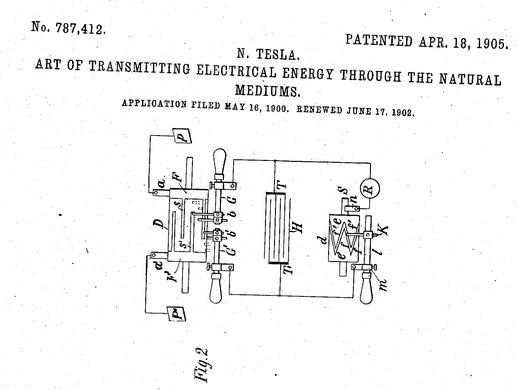
Thus, under the condition that the frequency of the standing wave in the ground coincides, and the frequency of contact closure in the receiver, the capacitor T gradually accumulated charge - and then forcibly discharged through the receiver R (allowing the discharge current of such a capacitor-drive to be recorded). What is explicitly the logic of the synchronous detector. At the same time, since the length of the wires connecting the capacitor to the ground was much less than the wavelength, then we cannot talk about EM pickups on such wires (from lightning strikes) - they will be insignificant.
Here is what Tesla himself wrote about this - and how his way began in this area:
It is the rule of law. It was clear that there wasn’t been a clear cloud of light. Heavy and long persisting arcs formed almost in regular time intervals. The observations were gained. I was prepared. The recording apparatus has been properly adjusted, it has become a fainter and fainter since it was ceased altogether. I was watching in eager expectation. Surely reckoning It has been the case that it has been repeated for the period of the past three weeks. But continued to manifest themselves with undiminished force. Subsequently, close observations were made by my assistant, Mr. Fritz Lowenstein, and shortly afterwards, several admirable opportunities haven’t been taken. I was observing stationary waves.
Based on the actual device of the detector, there is no doubt that the fact of the operation of such a detector — namely, a periodic sinusoidal change in the amplitude of the process’s energetics as it progresses and removes a thunderstorm (hundreds of miles) recorded by the detector — clearly indicated the standing voltage waves for the earth, which was for Tesla the starting point of his research.
In the aggregate of the information given above, there is every reason for setting up a full-scale experiment in order to finally confirm the Tesla Tower's operability.
If the presented material is too complicated to understand, then a more “humanitarian” exposition (sometimes bordering on impropriety, but giving a good understanding of what we are going to do in terms of the experiment) can be found, for example, via this link .
Authors: Sergey Plekhanov, Leonid Plekhanov
FAQ
Below is a list of the most frequently asked questions, with answers. If you have a question - please, before asking it, make sure that it is not listed below, or provide an argument - why the answer given below to this question is unconvincing.
• If this idea is working, will the currents in the soil of the earth kill all that is there?
There are no such risks. Just because the current density in the surface layer of the Earth will be scanty (take 2 kiloampere in the Tower, and distribute this current around the perimeter 20,000 km long and 100 meters deep; we get a current density of about 1 μA per square meter, which does not feel no living organism). Those. large alternating external potential from the charge on the ground (kilovolts and above) is combined with very small currents, and at the same time the vertical component of the electric field strength near the ground is small (much less than the background value of 130 volts per meter). As the height increases - the field strength (and without that small) will fall, so that the planes and satellites -) also do not threaten.
• You are making a planetary microwave.
The processes associated with the Tesla Tower have absolutely nothing to do with the mechanism of microwave heating of a substance. Of course, ohmic losses will be - but even gigawatts distributed over the area of the entire planet is the same as warming a sea with a match.
• You have an incorrect model in HFSS - you took two metal spheres and of course you got TM-mode.
No, we did not take the spheres from the conductors - but honestly laid the conductivity of the soil and the ionosphere, based on their tabular values. Accordingly, the size of the model is large (so that, due to the dielectric-ground cross-sectional area, it can be considered as a conductor).
• It is clear that TM-mode can be excited. But how, in practice, can the port be forwarded from the ground to the ionosphere?
And this does not need to be done - see the article above. It is enough to connect the generator only to the ground, the rest will be automatically induced by alternating currents in the vicinity of the Tower. Those. Formally, it can be considered an antenna - a circular area of soil near the tower, with a radius of the order of the wavelength
• Earth is a dielectric, so the current does not conduct, and nothing happens.
Soil perfectly conducts current, see above. At the dawn of the railway industry, the Earth served as a return conductor, and it worked perfectly fine as such (without making any noticeable resistance). In addition, if the ground as a whole were a poor conductor, ordinary grounding would be useless (that is, it would not work - but practice shows the opposite).
• You have a conventional radio antenna, the transmission efficiency will be negligible.
As shown above, the Tower has no relation to radio antennas - because it actually has no radio emission in the practical sense (that is, it is many orders of magnitude less than the losses due to ohmic resistance of the Tower).
• How does this all differ from Schumann? The usual resonance of Schumann, everyone knows it and therefore the idea is not workable. And nothing new in this.
The Schumann resonance is not a resonance of a particular mode, but a noise phenomenon at the first harmonics of the zero TM mode associated with the presence of pulsed pumping of the Earth-Ionosphere resonator at a frequency near the first mode (10 Hz, because on average about 40 50 lightning discharges, of which, according to statistics, only 20% -25% hit the ground), and with the fact that the average frequency of discharges is not evenly distributed over the surface of the planet (with a characteristic scale of non-uniformity of such a distribution, it is of the order of the first harmonic wavelength). In other words, the noise of the Schumann resonance is associated with the presence (albeit weak) of the spatial-temporal coherence of lightning strikes. Those. if lightning struck evenly across the surface, there would be no Schumann resonance (i.e. noise at the first harmonic frequencies). Or if the average frequency of the strike of lightning would not be 10 Hz, but 10 kHz, then the maximum energy would be entirely on other harmonics / modes. In addition, only the zero TM mode is excited in the Schumann resonance, and for our frequencies the following modes will be actively involved. Thus, although there is an indirect connection with the Schumann resonance - but our case is not the Schumann resonance. We really do not offer fundamentally new physical effects - everything is strictly within the framework of what has been known for a long time in the relevant sections of physics. We only “glued together” known knowledge in explaining the performance of the Tesla Tower.
• The quality of the resonance will be low - because, as a matter of fact, you have Schumann, so the standing wave will not work, there will be a traveling wave with a large attenuation.
Not true, firstly, we do not have Schumann - see the questions above, secondly, even for the first harmonics of the zero TM mode (i.e. for the Schumann resonance), the quality factor reaches 10 (see proofs above) that means the energy decay time is a few tenths of a second - i.e. lots of. And according to the actual experimental data, the quality factor with increasing harmonic number (ie, with increasing frequency) increases, and faster than the root of the frequency. So the standing wave will be, and the expected quality factor in our frequency range is at least several hundred.
• If in the ground there will be conductors electrically long relative to the wavelength - your wave will concentrate and attenuate on them.
Not true, conductors in the ground (for example, pipes of heating systems, etc.) mean locally improved conductivity of the soil, which will only lead to an increase in the quality of resonance — that is, increase the efficiency of energy transfer. In reality, only a conductor of sufficient length that is not in the ground, but grounded at one end, can work as such a “pulling off” conductor. Those are not observed (wires of power lines, despite the fact that they are of sufficient length, certainly not grounded - that is, they "do not see" the alternating potential of the soil, and pickups from the external field of the soil will be weak - because the field strength is small, see above - only the variable potential of the ground itself is great, but not the field from such a potential).
• With this approach, targeted delivery of energy is impossible, so there is no point in such a technology — even if it works.
You can not go by targeted delivery, but by controlling the delivery. Any receiver will generate a wave that can be easily detected. - — (.. ). , — .
• , ? - , ?
, . , . . , – , , ( — , .. – , — ).
• .
, . ( - ) ( - 100 ) — . .
• -, / , « ».
, — (.. ). , , ( ). , , «» — .
• / ?
. — ( ), — . — ( ), , .. « » . Those. - , .
• — ?
, . , , 15 , 30 000 ( 10 , ), « » (.. ) 2 . . , — . () , . , « » ( — .. ), — .
//--------------------------------------------------------------------------------//
UPDATE 2017.02.26:
, , .
. , — , , .. c . , . // . , , .
( ) (100% ) , . Those. , — , / / . , , , 10-100 /, FCC.
.. . — , , . — / .
, , , . .
Source: https://habr.com/ru/post/205900/
All Articles