Hood timer

During the last renovation of the apartment, I was thinking about improving the living standards. One of the facilities implemented was a timer for the hood in the bathroom. On the one hand, this increased comfort, since the device itself turned off the fan, on the other - it had a positive effect on the economy of electricity. The following is a description and implementation of the timer. It is easy to adapt for short-term inclusion of any power load capacity up to 1 kW.
The household exhaust fan is powered by 230 V AC and contains a 15… 60 W motor. Therefore, when designing the timer, it was decided to use the BT134 triac as a switching element. It withstands a constant current of up to 4 Amps and for such a load can work without a radiator.
The control part is made on a cheap 8-pin microcontroller. This allows you to modify the program to fit your specific needs. For example, add a humidity sensor or change the mode of operation and the measured time interval.
')
In this embodiment, implemented two modes of operation. After pressing the button, the timer turns on the fan and switches to 1 mode, signaling a green LED to glow. After a specified time (5 minutes), the hood turns off. If during the operation of mode 1 again to press the button, the timer will switch to mode 2 by turning on the red LED. In this mode, the fan runs continuously until the next button is pressed.
Electrical schematic diagram:
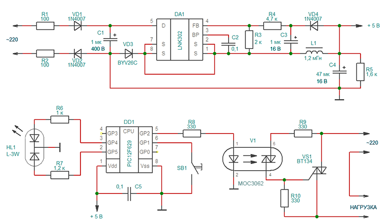
The power supply is made on a chip LNK302 production Power Integrations. Due to this, the resulting power source is small, with high efficiency and a small number of parts. The chip implements all basic protection: from short-circuit, from open-loop feedback, from emissions at the input, from overheating. I will not dwell on it in detail, since all the necessary information, if desired, can be found in the datasheet. Resistors R4 and R3 form a divider that determines the level of output voltage stabilization. Resistors R1 and R2 are used as a fuse, so it is desirable to use output MLT-0.25.
ATTENTION! The power source has a galvanic connection to the 230-volt network, so all installation and commissioning should be carried out with the device turned off and in compliance with safety regulations!
The timer and control part is performed on a PIC12F629 microcontroller. A two-color LED, a button and an optosimistor controlling the VS1 key are connected to it. A fuse is installed in the load circuit, not indicated in the diagram. Its value is selected based on the parameters of the fan.
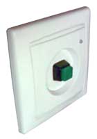
The implementation of the design depends on the specific conditions. I, for example, had a free box from the switch, so it was decided to mount a timer in it. Under the external design was adapted outlet for TV, bought in an electrical store. An antenna connector was thrown out of it, a case was drilled for mounting a two-color LED and a button was selected. Then divorced and manufactured circuit board. Therefore, be careful, you may need to adjust the attached printed circuit board for your case.
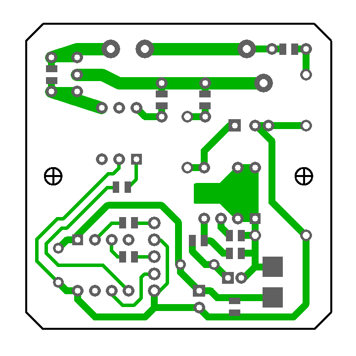
The printed circuit board is made of one-sided fiberglass with a size of 45 x 45 mm. Some elements on it are duplicated by SMD –cases, so that you can install what is available. I put the SMD choke, but if there is only a pin, you can drill holes in the pads for it.
PCB drawing (view from the soldering side):
Installation of lead elements:
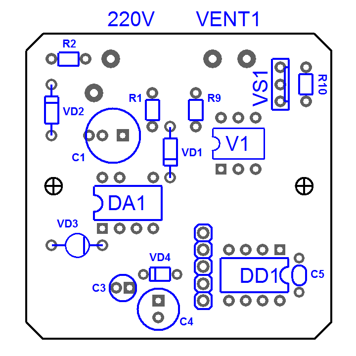
Installation of SMD elements:

Source code of the program:
title "TimerVent" ; errorlevel 0, -207, -302 #include <P12F629.inc> CBLOCK 0x020 ; tmp ; del, del_m ; cfg ; time_h, time_l ; ENDC __CONFIG _CPD_OFF & _CP_OFF & _BODEN_ON & _MCLRE_OFF & _PWRTE_ON & _WDT_OFF & _INTRC_OSC_NOCLKOUT #define SET_LED_K bsf GPIO, 5 ; #define SET_LED_Z bsf GPIO, 4 ; #define ZERO_LED_K bcf GPIO, 5 ; #define ZERO_LED_Z bcf GPIO, 4 ; #define SET_MOTOR bsf GPIO, 2 ; () KNOPKA equ 1 ; 1 org 0 goto INIT ; DEL_MK movwf del ; ( , 770 max) M1 decfsz del, F ;( W) goto M1 return DEL_M movwf del_m ; ( , 256 max) movlw 0xa5 ;( W) M2 call DEL_MK call DEL_MK decfsz del_m, F goto M2 return INIT bcf STATUS, RP0 ; 0 movlw B'00000111' movwf CMCON ; clrf GPIO bsf STATUS, RP0 ; 1 movlw B'00000010' movwf WPU movlw B'00000000' movwf OPTION_REG call 3FFh ; movwf OSCCAL movlw B'00000010' movwf TRISIO ; movlw B'00000010' ; movwf IOCB bcf STATUS, RP0 ; 0 clrf cfg ;----------------------[ ]-------------------------- SM btfsc GPIO, KNOPKA goto SM bcf T1CON, TMR1ON ; 1 movf cfg, F btfsc STATUS, Z goto MOD1 btfsc cfg, 0 goto MOD2 OUTP clrf GPIO ; "" clrf cfg movlw 0xfa ; 0,5 call DEL_M movlw 0xfa call DEL_M goto SM ;----------------------[ ]------------------------- MOD1 clrf cfg bsf cfg, 0 ZERO_LED_K SET_LED_Z SET_MOTOR movlw 0xfa ; 0,5 call DEL_M movlw 0xfa call DEL_M movlw b'00110100' ; 1 movwf T1CON clrf TMR1H clrf TMR1L clrf time_l clrf time_h bsf T1CON, TMR1ON ; 1 M3 btfss GPIO, KNOPKA goto SM btfss PIR1, TMR1IF ; goto M3 bcf PIR1, TMR1IF ; , incf time_l, F btfsc STATUS, Z incf time_h, F movlw 0x58 ; xorwf time_l, W btfss STATUS, Z goto M3 movlw 0x01 ; xorwf time_h, W btfss STATUS, Z goto M3 goto OUTP ;----------------------[ ]-------------------------- MOD2 clrf cfg bsf cfg, 1 SET_LED_K ZERO_LED_Z SET_MOTOR movlw 0xfa ; 0,5 call DEL_M movlw 0xfa call DEL_M M4 btfsc GPIO, KNOPKA goto M4 goto OUTP END ;--------------------------------------------------------------------------- ; DEL_MK: ; 0x20 - 100 ; 0xa5 - 500 ;--------------------------------------------------------------------------- ; cfg: ; "0" - , " " () ; "1" - , " " () ; "2" - ; "3" - ; "4" - ; "5" - ; "6" - ;--------------------------------------------------------------------------- Source: https://habr.com/ru/post/205484/
All Articles