How to make a dosimeter and bind it to Android

Hello, in this article I would like to share my experience on how I went from the idea to the finished device.
I really like to read Habr, and so I came across an article about how quickly and without troublesome a dosimeter can be tied to an iphone ( article ). I was very interested in the article written by lexeresser and I wanted to try to do this, but I came across difficulties: the first moment was a household dosimeter, which is described as not so easy to buy, I found only two for sale and they are not sold in Russia, the second moment was described in article program for iphone, and I have a smartphone on Android. I set myself the task to meet the 1000 rubles, because dosimeters cost from 3500 rubles. In order to meet the budget, I decided not to look for a ready-made device, but to make it myself, but to create a program for an android. I called this project SyGeiger and it does not carry a commercial idea, it is just for the fan: Will I be able to?
Rummaging through the Internet and looking at a bunch of circuits and implemented for itself the most simple, without microcontrollers, indicators and extra strapping. It was decided to make the power from 3 volts (two finger batteries, because they are easiest to find). For the initial indication was chosen piezo dynamics.
')
Dosimeter circuit:
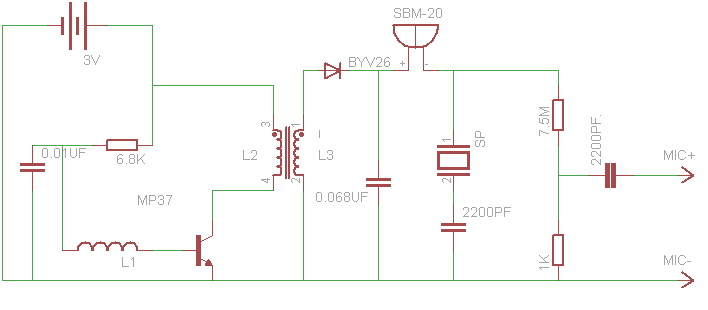
Explanations to the scheme: SP - piezo-dynamics, SBM-20 - sensor SBM-20, L1, L2, L3 - transformer windings, MIC - microphone output
And so I used to implement the scheme:
- sensor SBM-20
- 2 finger batteries
- piezodynamic
- plastic case with battery compartment
- switch
- resistors 6.8 kΩ, 7.5 MΩ, 1 kΩ
- capacitors 0.01 microfarad, 0.068 microfarad, 2 pieces of 2200pF
- diode BYV 26 (high voltage diode)
- transistor MP-37 (Soviet, that was on hand and then put)
- transformer (wound itself, the explanation below)
- plug for headset
The most important thing in the circuit is the transformer and sensor SBM-20. The sensor I ordered through the site for 800 rubles with delivery (be careful very deformable, because copper). The core of the transformer is ferrite, the transformer was taken from the fluorescent lamp for the base and rewound. A step-up transformer is needed for the sensor SBM-20, because it operates from 400V; it consists of three windings: the first winding contains 4 turns of PEL-0.1 mm wire, the second 4 turns of PEL-0.5mm wire, the third - 900 turns of PELSHO-0.1mm wire.
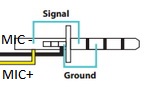
Wiring connection of the output to the microphone plug:
When assembling, be careful - HIGH VOLTAGE, kill does not kill, but you can burn the scheme.
I put the sensor across the body, because I couldn’t fit it anymore, I didn’t want to remove the battery compartment (it would not have been nice). I divided the circuit into three modules: a voltage converter module for the sensor, a signal converter module for the microphone input, and a sensor itself.
Type of device:
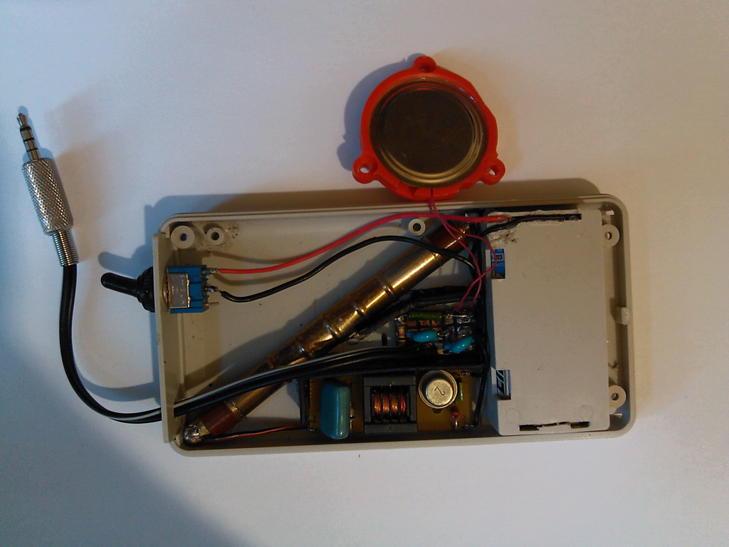
when open, all modules are enclosed by plastic partitions
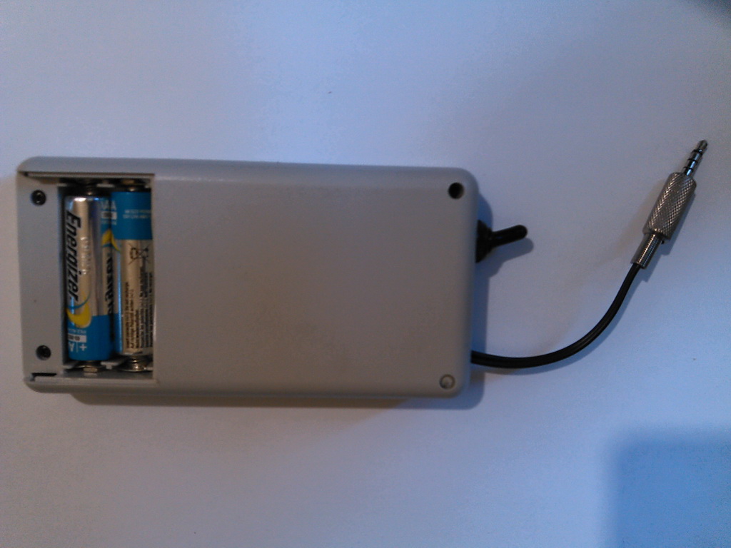
rear view, battery compartment
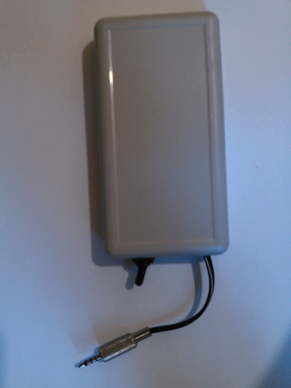
assembled view from the front side, you need to make a sticker with the instruction
The second stage of work consisted of writing a program on Androyd, the difficulty was that I NEVER programmed in Java. For a couple of days I installed eclipse and read the instructions for dummies and wrote a program. All the complexity for me was in creating a separate stream and reading in real time the clipboard from the microphone.
SyGeiger program:
- link to source
- program link
Work principle video:
PS: Seven days passed from idea to implementation, I was in no hurry. The device can be reduced two to three times, but I did not have such a task. I also checked the battery life of the device - it worked for three days and I turned it off, tired of waiting, consumes very little. There is an idea of implementing this device using GPS on a smartphone: you go by car, and it registers the background radiation on the map. If someone implements a broader program functionality or errors, email me. Everyone who read and appreciated the article thanks a lot.
Source: https://habr.com/ru/post/204808/
All Articles