Directional lighting and shading in 2D space

Good afternoon, Habravchane!
I would like to talk about one of the ways of rendering lighting and shading in 2D-space, taking into account the geometry of the scene. I really like the implementation of lighting in Gish and Super MeatBoy, although in mitboi it can only be seen at dynamic levels with collapsing or moving platforms, and in Guiche it is everywhere. The lighting in such games seems to me to be so “warm”, tube-like, that I definitely wanted to implement something similar myself. And that's what came of it.
Thesis of what is and what needs to be done:
- there is some 2D world in which you need to embed dynamic lighting + shading; the world is not necessarily tiled, from any geometry;
- light sources should be, in principle, an unlimited number (limited only by the performance of the system);
- the presence of a large number of light sources at a single point, or a single light source with a large “illumination” coefficient, should not only illuminate the area at 100%, but should light it;
- everything should be calculated, of course, in real-time;
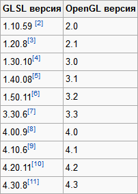
All this required OpenGL, GLSL, FrameBuffer technology and a bit of math. Limited to versions of OpenGL 3.3 and GLSL 3.30 because the video card of one of my systems is quite outdated by today's standards (GeForce 310), and this is more than enough for 2D (and earlier versions cause rejection due to inconsistency between the versions of OpenGL and GLSL). The algorithm itself is not complicated and is done in 3 steps:
- Form a texture the size of the black render area and draw lighted areas in it (the so-called irradiance map), accumulating the illumination factor for all points;
- Render the scene to a separate texture;
- In the context of the render, output a quad that completely covers it, and in the fragment shader, mix the resulting textures. At this stage, you can “play around” with a fragmentary shader, adding, for example, the effects of water / fire refraction, lenses, color correction for every taste and other post-processing.
1. Lighting map
We will use one of the most common technologies -
I do not pretend at all to the reasonableness and optimality of this approach, the lighting algorithms are enough and each has its own advantages and disadvantages. While braining, the way seemed quite rightful to life, and I set about implementing it. I note that at the time of writing this article I found this way ... well, okay, so the bicycle is a bicycle.
')
1.1 Z-buffer aka depth buffer
The essence of the Z-buffer is the storage of the remoteness of the scene element from the camera, which allows you to cut off pixels that are invisible behind more near objects. If in the 3D scene the depth buffer is a plane
then in our flat world it will become a line or a one-dimensional array. Light sources - point, emitting light from the center in all directions. Accordingly, the buffer index and value will correspond to the polar coordinates of the location of the object closest to the source. I determined the size of the buffer empirically, as a result of which I stopped at 1024 (of course, it depends on the window size). The smaller the buffer dimension, the greater the difference between the object boundary and the illuminated area, especially in the presence of small objects, and in some places completely unacceptable artifacts will appear:
Hidden text
Buffer Algorithm:
- fill in the value of the radius of the light source (the distance at which the illumination power reaches zero);
- for each object located in the radius of the light source, take those edges that are turned to the light source face. If you take the edges turned by the back side, the objects will automatically become highlighted, but there will be a problem with nearby:Hidden text
- project the resulting list of edges, converting their Cartesian coordinates into polar light sources. Recalculate point (x; y) in (φ; r):
φ = arccos (xAxis • normalize (point))
Where:
• - scalar product of vectors;
xAxis is the unit vector corresponding to the x (1; 0) axis, since 0 degrees correspond to the point right from the center of the circle;
point is a vector directed from the center of the light source to the point belonging to the edge (coordinates of the edge point in the coordinate system of the light source);
normalize - vector normalization;
r = | point | - distance to the point;
We project the two extreme points of the edge and intermediate. The number of points needed for conversion corresponds to the number of buffer cells that are covered by the projection of the edge.
Calculate the buffer index corresponding to the angle φ:
index = φ / (2 * π) * size of the Buffer;
Thus, we find two extreme buffer indices corresponding to the extreme points of the edge. For each intermediate index, we convert to the angle value:
φ = index * 2 * π / Buffer size
, we construct avectorsegment from (0; 0) at this angle of length equal to or greater than the radius of the light source:
v = vec2 (cos (φ), sin (φ)) * radius
and find the point of intersection of the obtained segment and the edge, for example, like this:- 2 lines with coefficients A 1 , B 1 , C 1 and A 2 , B 2 , C 2 are set
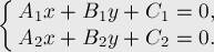
- using the Kramer method to solve this system of equations, we obtain the intersection point:

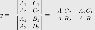
- if the denominator is zero (in our case, if the value of the denominator modulo less than some error value, for float), then there are no solutions — the lines either coincide or are parallel;
- check the location of the resulting point within both segments.
And the last step is to translate all the obtained intermediate points into polar coordinates. If the distance to the point is less than the value of the buffer at the current index, then write to the buffer. The buffer is now ready for use. On this, in principle, all mathematics ends. - 2 lines with coefficients A 1 , B 1 , C 1 and A 2 , B 2 , C 2 are set
1.2 Vertex frame
Now it is necessary to construct a polygonal model, which covers the entire area that illuminates the light source, according to the data in the depth buffer. For this, it is convenient to use the Triangle Fan method.

The polygon is formed from the first point, the previous one and the current one. Accordingly, the first point is the center of the light source, and the coordinates of the other points:
for( unsigned int index = 0; index < bufferSize; ++index ) { float alpha = float( index ) / float( bufferSize ) * Math::TWO_PI; float value = buffer[ index ]; Vec2 point( Math::Cos( alpha ) * value, Math::Sin( alpha ) * value ); Vec4 pointColor( color.R. color.G, color.B, ( 1.0f - value / range ) * color.A ); ... } and close the chain by duplicating the zero index. The color of all points is the same after the difference in the brightness
At this stage, it is also possible to forcibly distance the obtained points by a certain value so that the surface on which the rays fall is illuminated, creating the appearance of volume.
1.3 Framebuffer
One texture bound to the framebuffer, the GL_RGBA16F format, is enough; such a format will allow storing values beyond [0.0; 1.0] with half-precision floating-point accuracy.
Little 'pseudocode'
GLuint textureId; GLuint frameBufferObject; //. width height - glGenTextures( 1, &textureId ); glBindTexture( GL_TEXTURE_2D, textureId ); glTexImage2D( GL_TEXTURE_2D, 0, GL_RGBA16F, width, height, 0, GL_RGBA, GL_UNSIGNED_BYTE, NULL ); glTexParameterf( GL_TEXTURE_2D, GL_TEXTURE_WRAP_S, GL_CLAMP_TO_EDGE ); glTexParameterf( GL_TEXTURE_2D, GL_TEXTURE_WRAP_T, GL_CLAMP_TO_EDGE ); glTexParameteri( GL_TEXTURE_2D, GL_TEXTURE_MAG_FILTER, GL_LINEAR ); glTexParameteri( GL_TEXTURE_2D, GL_TEXTURE_MIN_FILTER, GL_LINEAR ); glBindTexture( GL_TEXTURE_2D, 0 ); // glGenFramebuffers( 1, frameBufferObject ); glBindFramebuffer( GL_FRAMEBUFFER, frameBufferObject ); // glFramebufferTexture2D( GL_FRAMEBUFFER_EXT, GL_COLOR_ATTACHMENT0, GL_TEXTURE_2D, textureId, 0 ); // glBindFramebuffer( GL_FRAMEBUFFER, 0 ); // , - ... if( glCheckFramebufferStatus( GL_FRAMEBUFFER_EXT ) != GL_FRAMEBUFFER_COMPLETE ) { ... } ... Bind the buffer, set the additive blend of glBlendFunc (GL_ONE, GL_ONE) and “draw” the lighted areas. Thus, the alpha channel will accumulate the degree of illumination. You can also add global illumination by drawing a quad in the whole window.
1.4 Shaders
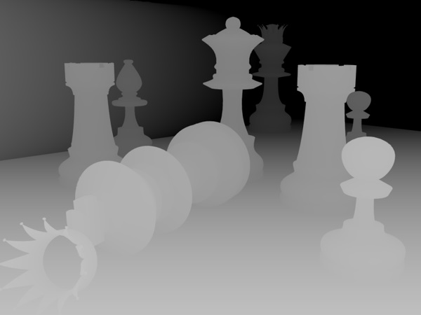
Vertex shaders for drawing rays from light sources are standard, taking into account the camera position, and in the fragment shader we accumulate color with regard to brightness:
layout(location = 0) out vec4 fragData; in vec4 vColor; ... void main() { fragData = vColor * vColor.a; } As a result, we should get something like this:

2. Render scenes in texture
It is necessary to render the scene into a separate texture, for which we create another framebuffer, attach the usual GL_RGBA texture and render the render in the usual way.
Suppose there is such a scene from the notorious platformer:

3. Combining a lighting map with a scene
The fragment shader should be something like this:
uniform sampler2D texture0; uniform sampler2D texture1; ... vec4 color0 = texture( texture0, texCoords ); // vec4 color1 = texture( texture1, texCoords ); // fragData0 = color0 * color1; There is simply no place. Here, before the multiplication of the color of the scene color0, you can add a certain coefficient in case the setting of the game is extremely dark and you need to see the rays of light.
Hidden text
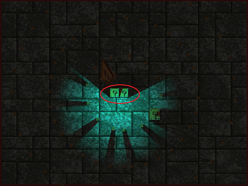
fragData0 = ( color0 + vec4( 0.05, 0.05, 0.05, 0.0 ) ) * color1; And here…

If the character does not describe a simple geometry, then the shadow of it will be very, very wrong. Our shadows are built from geometry, respectively, the shadows from a sprite character are obtained as from a square (hmm, but Mitbay, I wonder, from what considerations is square?). So the textures of the sprites should be drawn as “square” as possible, leaving as few transparent areas as possible along the edges? This is one of the options. Can the character's geometry be described in more detail by smoothing the corners, but not describing the same geometry for each frame of the animation? Suppose, smooth corners, now the character is almost an ellipse. If the scene is completely dark, then such a shadow is strongly striking. Adding anti-aliasing of the irradiance map and global illumination makes the picture more acceptable:
vec2 offset = oneByWindowCoeff.xy * 1.5f; // fragData = ( texture( texture1, texCoords ) + texture( texture1, vec2( texCoords.x - offset.x, texCoords.y - offset.y ) ).r + texture( texture1, vec2( texCoords.x, texCoords.y - offset.y ) ).r + texture( texture1, vec2( texCoords.x + offset.x, texCoords.y - offset.y ) ).r + texture( texture1, vec2( texCoords.x - offset.x, texCoords.y ) ).r + texture( texture1, vec2( texCoords.x + offset.x, texCoords.y ) ).r + texture( texture1, vec2( texCoords.x - offset.x, texCoords.y + offset.y ) ).r + texture( texture1, vec2( texCoords.x, texCoords.y + offset.y ) ).r + texture( texture1, vec2( texCoords.x + offset.x, texCoords.y + offset.y ) ).r ) / 9.0; where oneByWindowCoeff is the coefficient for converting pixel coordinates to texel coordinates.
In the absence of global illumination, it may be better to turn off shadows like “characters” or make them luminous themselves (ideal, in my opinion, option), well, or be confused and describe the geometry of the object for all animations.
I recorded a small demonstration that came out of all these reflections and finishings:
4. Optimization
As they say, "Write first and then optimize." The original code was drafted quickly and roughly, so there was enough room for optimization. The first thing that came to mind was to get rid of the excessive number of polygons that render the illuminated areas. If there are no obstacles in the radius of the light source, then there is no point in drawing 1000+ polygons, we don’t need such a perfect circle, the eye simply does not perceive the difference (or maybe this monitor is too dirty for me).
For example, for a depth buffer of 1024 without optimization:
Hidden text
and with optimization:
Hidden text
For scenes with an abundance of static objects, you can cache the results of calculations of projecting objects into the buffer, which gives a good gain, since the number of cosines / roots and other expensive mathematics is reduced. Accordingly, for each buffer we set up a list of pointers to objects, check for changes in their parameters affecting the position or shape, and then either fill the cache straight into the buffer, or recalculate the object completely.
5. Conclusion
This lighting technique does not claim to be optimal, speed and accuracy, the goal was the fact of implementation. There are different techniques, such as building some shadows (the same lighting, as I understand, dopilivaetsya additionally), but soft , with an abundance of calculations, or even such extremely entertaining , found already in the process of writing the article (in general, the logic is similar to that I used).
In general, what was in the plans was realized, the objects cast shadows, the necessary oppressive atmosphere in the game was created, and the picture became more pleasant in my opinion.
6. References
- Video demonstration of the result ;
- source code (github) of the depth buffer ;
- the source code (github) of a non-game demo (although currently in the game I use a more doped version, specially sharpened for it);
- Win32-build mini-demo ;
- OpenGL 3.3 specification ;
- GLSL 3.3 specification .
Source: https://habr.com/ru/post/204782/
All Articles