Timelapse timer on arduino
Hi, Habr!
One of my hobbies is, no matter how trite, is photography. Half a year ago, he thought about creating timelaps. To create timelaps requires a timer on which you can set the shutter frequency of the camera. In search of a ready and cheap solution, there were attempts to order a device on ebay, but since the Russian Post lost my long-awaited timer twice, I decided to make it myself.
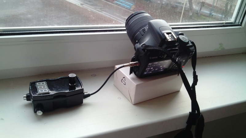
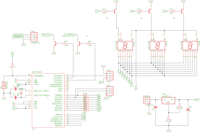
The idea of the device is simple: the signal from the potentiometer enters the ADC of the controller, thereby setting the interval of the output signal to the camera. This interval will be displayed on 2 indicators, the 3rd indicator will indicate the unit of measurement for the interval (seconds or minutes), as well as light the point if the potentiometer value has not changed for more than 1 second. This indication was needed to solve one problem, which will be discussed below, in the end it was not superfluous. Also on the device, I provided a couple of buttons for manually giving a signal to the shutter and focus.
')
Managing 7 segment indicators is quite simple.
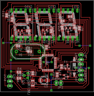
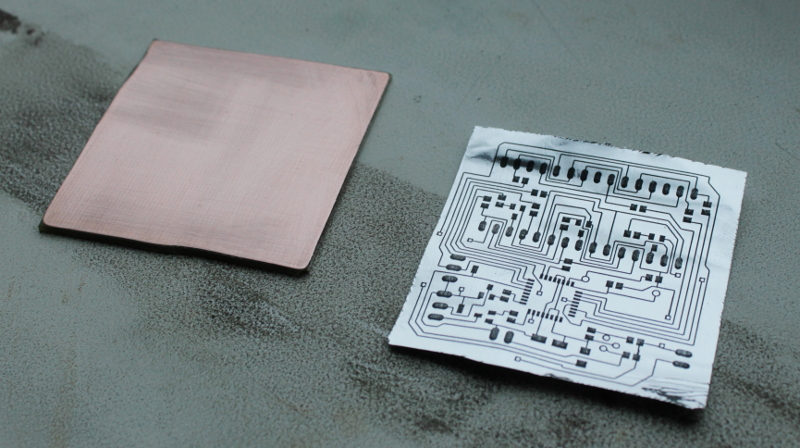
Bred in Eagle-Cad . Naturally I tried to do everything on SMD elements and as compact as it can be printing on foil and etching in ferric chloride. As a result, a 5x5 cm board appeared.
In live.
After that, he translated the drawing to textolite, etched it, and made a foil. The result is in the picture.
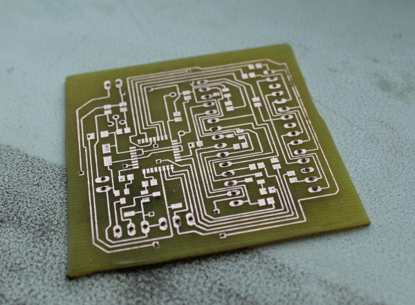
I tried for the first time to apply a mask, but the first pancake was lumpy.
After soldering most of the components, it’s time to work with the firmware. First, pour the Arduino NG bootloader onto the ATmega8L . Second, write the program code. And in the first stage, I realized that the task is not so simple, because the Arduino NG is based on ATmega8 and works with 16 MHz quartz, unlike ATmega8L , which works with 8 MHz quartz. But the benefit of the Internet is a lot of information on this topic, such as a bootloader, which helps to make the Arduino with 8 MHz quartz on 8L (link to bootloader) . I also filled it through Arduino IDE. Alas, the loader constantly flew after flashing the first sketch. I could not fix this problem, so I had to re-fill it. If anyone knows how to properly lock, I will be glad to help.
After that, I began to write a sketch code, but since my programming knowledge is limited to Pascal, a freshman and simple examples for STM8, I turned to an ftp27 colleague who decided to help me with ardent enthusiasm.
The main problem was to maintain a dynamic display cycle while simultaneously counting the timer to produce a snapshot. Fortunately, Arduino provides a nice function mills () , which returns the number of milliseconds since the device was turned on. Since the device was not intended to be used for more than 1 day, this function was ideally suited for timing.
This program reads the value from the ADC, checks whether the timing has changed, and if it has changed, it takes a picture with a new timer. Since the value of the ADC is quite noticeably running even if you do not touch the potentiometer, it was decided to take no more than 16 times.
For greater economy, it was decided to turn off the display 10 seconds after the last change of the potentiometer value. Saved 30 mA - a trifle, but nice.
All firmware and circuit files can be found here (link) .
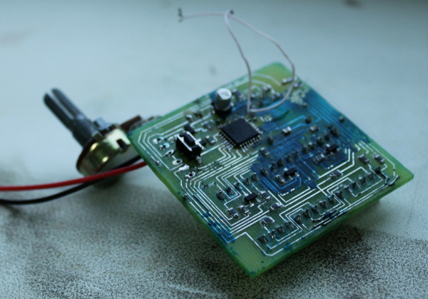
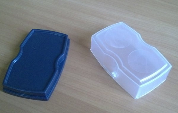
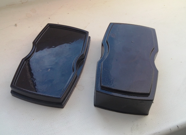
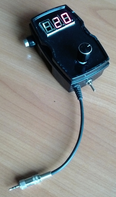
After conducting a series of tests and uploading the final firmware, the rest of the elements were soldered. The next task was to put all this miracle in a compact case. A box made of a sponge for shoes ideally suited as a case. Having painted it black and drilling the necessary holes, we fitted the board and sealed it with glue for reliability.
Before
After
The result was a good device with a cost of 200 rubles, which works fine.

Of course, it was possible to go along the trodden path and do everything on the NE555 , but I really wanted an indication and more convenient timing of the timer.
On the same day, they removed their first time-lapse right from the window of the workplace gif 8Mb .
One of my hobbies is, no matter how trite, is photography. Half a year ago, he thought about creating timelaps. To create timelaps requires a timer on which you can set the shutter frequency of the camera. In search of a ready and cheap solution, there were attempts to order a device on ebay, but since the Russian Post lost my long-awaited timer twice, I decided to make it myself.
Concept development
The idea of the device is simple: the signal from the potentiometer enters the ADC of the controller, thereby setting the interval of the output signal to the camera. This interval will be displayed on 2 indicators, the 3rd indicator will indicate the unit of measurement for the interval (seconds or minutes), as well as light the point if the potentiometer value has not changed for more than 1 second. This indication was needed to solve one problem, which will be discussed below, in the end it was not superfluous. Also on the device, I provided a couple of buttons for manually giving a signal to the shutter and focus.
')
Managing 7 segment indicators is quite simple.
Schematic diagram of the device
Bred in Eagle-Cad . Naturally I tried to do everything on SMD elements and as compact as it can be printing on foil and etching in ferric chloride. As a result, a 5x5 cm board appeared.
In live.
After that, he translated the drawing to textolite, etched it, and made a foil. The result is in the picture.
I tried for the first time to apply a mask, but the first pancake was lumpy.
Firmware
After soldering most of the components, it’s time to work with the firmware. First, pour the Arduino NG bootloader onto the ATmega8L . Second, write the program code. And in the first stage, I realized that the task is not so simple, because the Arduino NG is based on ATmega8 and works with 16 MHz quartz, unlike ATmega8L , which works with 8 MHz quartz. But the benefit of the Internet is a lot of information on this topic, such as a bootloader, which helps to make the Arduino with 8 MHz quartz on 8L (link to bootloader) . I also filled it through Arduino IDE. Alas, the loader constantly flew after flashing the first sketch. I could not fix this problem, so I had to re-fill it. If anyone knows how to properly lock, I will be glad to help.
After that, I began to write a sketch code, but since my programming knowledge is limited to Pascal, a freshman and simple examples for STM8, I turned to an ftp27 colleague who decided to help me with ardent enthusiasm.
The main problem was to maintain a dynamic display cycle while simultaneously counting the timer to produce a snapshot. Fortunately, Arduino provides a nice function mills () , which returns the number of milliseconds since the device was turned on. Since the device was not intended to be used for more than 1 day, this function was ideally suited for timing.
This program reads the value from the ADC, checks whether the timing has changed, and if it has changed, it takes a picture with a new timer. Since the value of the ADC is quite noticeably running even if you do not touch the potentiometer, it was decided to take no more than 16 times.
For greater economy, it was decided to turn off the display 10 seconds after the last change of the potentiometer value. Saved 30 mA - a trifle, but nice.
All firmware and circuit files can be found here (link) .
Device assembly
After conducting a series of tests and uploading the final firmware, the rest of the elements were soldered. The next task was to put all this miracle in a compact case. A box made of a sponge for shoes ideally suited as a case. Having painted it black and drilling the necessary holes, we fitted the board and sealed it with glue for reliability.
Before
After
The result was a good device with a cost of 200 rubles, which works fine.
Of course, it was possible to go along the trodden path and do everything on the NE555 , but I really wanted an indication and more convenient timing of the timer.
On the same day, they removed their first time-lapse right from the window of the workplace gif 8Mb .
Source: https://habr.com/ru/post/204446/
All Articles