SSAO on OpenGL ES 3.0

One day, looking at another demo with effect, the question arose: is it possible to make SSAO on a mobile device so that it looks good and does not slow down?
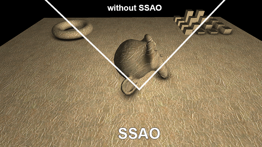
The device was taken Galaxy Note 3 n9000 (mali T62), the goal - FPS is not lower than 30, and the quality should be as in the picture above.
I will not go into details about this effect, it is assumed that the reader can learn about the effect from other sources ( wiki or steps3d ). The article focuses on adaptation for a mobile platform, however, a brief overview will be made in the section "SSAO species".
SSAO has a rather gluttonous effect in terms of performance and, at the same time, quite invisible to the average user, so I still haven’t seen it on a mobile device. Especially to speed it up, you need support for MRT , which appeared only in OpenGL ES version 3.0.
SSAO Varieties
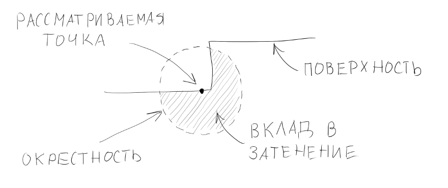
The basic idea of the algorithm is to determine the shading of a surface point in space. In order to determine the degree of shading of this point in a certain radius from it, the presence of objects is checked, the more in the vicinity of the objects, the more shadowed the point is.
Of course, it is impossible to calculate the shading for each point on surfaces in three-dimensional space, so the entire work of the algorithm is carried out in image space (hence the name screen space ambient occlusion). In other words, the pixel on the screen acts as a point on the surface (in fact, not necessarily on the screen, the SSAO buffer size is often smaller than the screen size, so it would be more correct to say a pixel in a frame or frame). It is also impossible to process the values of all points of space in the neighborhood, therefore they are usually limited to a small sample of random points within a certain radius from the point in question.
')
In the simplest implementation, a depth buffer is sufficient to calculate the shading — so the z-coordinate of the pixel in question is compared with the z-coordinates of the pixels from the sample, and based on this difference, shading is considered.
However, look at the picture above - it shows that the (“useless”) contribution to the shading is also made by the surface itself under the point. As a result, the picture is obtained in gray tones, that is, where there should not be shading - it is there. It looks like this:
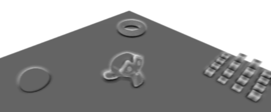
In order to avoid this, in addition to information about the depth, we need more information about the normal at this point. To do this, during the rendering of the scene in addition to the color, it is also recorded in a separate normal buffer. Given these, you can change the position of the point from the sample so that it makes a “useful” contribution. This is done on the basis of the angle between the normal at the point in question and the point normal from the sample, if it (angle) is more than 90 ° - the normal is inverted from the sample and its point is recalculated on its basis. This modification of the algorithm gives shading only where it is needed, but it has a serious drawback - for each point from the sample, in addition to reading from the depth buffer, an additional reading from the normal texture appears. And the bottleneck in SSAO is a large number of reads from different buffers, and these readings are performed in random order, which is a kill for the cache. Especially on a mobile device.
Another modification implies using as a neighborhood not a sphere, but a hemisphere within which points from the sample are located. In this case, it is necessary to orient this sphere along the normal of the point in question.
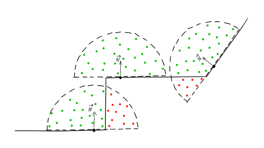
In this case, it is not necessary to read the normals for each point from the sample, since all of them are already located as it should, it is enough to get the normal to the point in question.
In my opinion this is the best modification, and it is applicable.
Implementation
First we need buffers for storing normals, depth and color. Here we use technology from OpenGL ES 3.0 - Multiple Render Targets, we create several buffers, and then write to them at the same time. In the code, it looks like this (I rendered the creation of a texture into a separate function):
// , ( ), GLenum buffers[] = {GL_COLOR_ATTACHMENT0, GL_COLOR_ATTACHMENT1}; GLuint fbo; GLuint colorBuff; GLuint normBuff; GLuint depthBuff; // void createTexture(GLuint &id, int inFormat, int w, int h, int format, int type, int filter, int wrap, void* pix=NULL) { glGenTextures(1, &id); glBindTexture(GL_TEXTURE_2D, id); glTexImage2D(GL_TEXTURE_2D, 0, inFormat, w, h, 0, format, type, pix); glTexParameteri(GL_TEXTURE_2D, GL_TEXTURE_MAG_FILTER, filter); glTexParameteri(GL_TEXTURE_2D, GL_TEXTURE_MIN_FILTER, filter); glTexParameteri(GL_TEXTURE_2D, GL_TEXTURE_WRAP_S, wrap); glTexParameteri(GL_TEXTURE_2D, GL_TEXTURE_WRAP_T, wrap); } ... glGenFramebuffers(1, &fbo); // glBindFramebuffer(GL_FRAMEBUFFER, fbo); // width height - createTexture(colorBuff, GL_RGB8, width, height, GL_RGB, GL_UNSIGNED_BYTE, GL_NEAREST, GL_MIRRORED_REPEAT); createTexture(normBuff, GL_RGB8, width, height, GL_RGB, GL_UNSIGNED_BYTE, GL_NEAREST, GL_MIRRORED_REPEAT); createTexture(depthBuff, GL_DEPTH_COMPONENT24, width, height, GL_DEPTH_COMPONENT, GL_UNSIGNED_INT, GL_NEAREST, GL_MIRRORED_REPEAT); // , glFramebufferTexture2D(GL_FRAMEBUFFER, GL_COLOR_ATTACHMENT0, GL_TEXTURE_2D, colorBuff, 0); glFramebufferTexture2D(GL_FRAMEBUFFER, GL_COLOR_ATTACHMENT1, GL_TEXTURE_2D, normBuff, 0); glFramebufferTexture2D(GL_FRAMEBUFFER, GL_DEPTH_ATTACHMENT, GL_TEXTURE_2D, depthBuff, 0); int err = glCheckFramebufferStatus(GL_FRAMEBUFFER); if (err != GL_FRAMEBUFFER_COMPLETE) LOGE("Main framebuffer error: %i", err); glDrawBuffers(2, buffers); Further in a similar way, but already with one texture, you need to create a buffer for SSAO.
SSAO buffer
glGenFramebuffers(1, &ssaoFbo1); glBindFramebuffer(GL_FRAMEBUFFER, ssaoFbo1); // , , GL_R8 createTexture(ssaoBuff1, GL_R8, width/ssaoScaleW, height/ssaoScaleH, GL_RED, GL_UNSIGNED_BYTE, GL_LINEAR, GL_MIRRORED_REPEAT); glFramebufferTexture2D(GL_FRAMEBUFFER, GL_COLOR_ATTACHMENT0, GL_TEXTURE_2D, ssaoBuff1, 0); // glDrawBuffers , This buffer may be smaller, but for now let's make it the same as the screen resolution (in my case, 1920x1080).
Separately it is necessary to say about the z-buffer. To be used in SSAO, it must first be made linear, otherwise the mean and background will lose much accuracy. Usually, for this, the depth values are written in a separate buffer, often with normals. However, the additional buffer does not bode well for performance, so we will not linearize the values and write them to a separate buffer, but directly to the current, standard depth buffer (gl_FragDepth). This can cause artifacts in the foreground (very close, almost near the front cut-off plane), but in general this buffer behaves quite normally.
The scene is rendered as usual, with the only difference being that, in addition to color, we also write normals and slightly change the depth buffer. Vertex shader for scene rendering:
#version 300 es uniform mat4 matrixProj; uniform mat4 matrixView; uniform vec3 lightPos; layout(location = 0) in vec3 vPos; // layout(location = 1) in vec3 nPos; // layout(location = 2) in vec3 tPos; // layout(location = 3) in vec2 tCoord; // out vec3 light; out vec3 gNorm; out float zPos; out vec2 texCoord; void main() { vec4 p = matrixProj*matrixView*vec4(vPos, 1.0); gl_Position = p; texCoord = tCoord; // , vec3 bitangent = cross(tPos, nPos); mat3 tbn = mat3(tPos, bitangent, nPos); light = normalize(lightPos-vPos)*tbn; zPos = pz; // z- - vec4 n = (matrixView*vec4(nPos, 0.0)); // gNorm = normalize(n.xyz); } Fragment Shader:
#version 300 es precision highp float; // 24- , , 24 , uniform sampler2D texDiff; // uniform sampler2D texNorm; // layout(location = 0) out vec3 colorBuff; // layout(location = 1) out vec3 normBuff; // in vec3 light; in vec3 gNorm; in float zPos; in vec2 texCoord; const vec3 ambientColor = vec3(0.3); const float zFar = 40.0; // void main() { vec3 n = normalize(texture(texNorm, texCoord).xyz*2.0-1.0); vec3 l = normalize(light); vec3 c = texture(texDiff, texCoord).rgb; float a = clamp(dot(n, l), 0.0, 1.0); colorBuff = c*(a+ambientColor); // normBuff = normalize(gNorm)*0.5+0.5; // gl_FragDepth = zPos/zFar; // } We also need an array of random points in the hemisphere (the sample itself). In order for the shading to turn out beautiful (if you can say so, more physical) - the density of the points in the hemisphere must be higher towards the center and lower towards the border. That is, to have a normal distribution law.
for (int i=0; i<samples; i++) { rndTable[i] = vec3(random(-1, 1), random(-1, 1), random(-1, -0)); // ( ) rndTable[i].normalize(); // rndTable[i] *= (i+1.0f)/samples; // ( ) } 

Of course, the number of points in the sample will not be so large. Let's make so far equal to 10.
However, such a sample with pseudo-random values is small - these values are random only within one fragment, the next fragment will take the same points, albeit with a slight offset. To eliminate this drawback, a small texture (approximately 4x4 pixels) with pseudo-random values is usually used. Now, in each fragment, we can take values from this texture and form a rotation matrix for them from our hemisphere points. And at the same time turn them relative to the normal, which we will read already from the texture of the normals. Thus, multiplying the points by the resulting matrix, we will simultaneously orient them relative to the normal and rotate by a pseudo-random vector. The construction of such a matrix is called the Gram-Schmidt process .
In the shader, it will look like this:
vec3 normal = texture(normBuff, texCoord).xyz*2.0-1.0; vec3 rvec = texture(randMap, texCoord*scr).xyz*2.0-1.0; vec3 tangent = normalize(rvec-normal*dot(rvec, normal)); vec3 bitangent = cross(tangent, normal); mat3 rotate = mat3(tangent, bitangent, normal); We also need to restore the coordinates of a point in space. To do this, you can multiply the coordinates of a point in the image space by the inverse matrix of the perspective transformation, or you can do more simply: multiply the vector (ray) directed from the camera through the current pixel by the value of the z-coordinates of this pixel. Z-coordinates are stored in the depth buffer, and the beam from the camera is based on the viewing angle, which is used when building the perspective matrix (projection matrix) - this is fov. I decided to save on uniform-ah, and just scored this value in the vertex shader as a constant.
#version 300 es const fov = 0.57735; layout(location = 0) in vec2 vPos; layout(location = 1) in vec2 tCoord; uniform float aspect; out vec2 texCoord; out vec3 viewRay; void main() { gl_Position = vec4(vPos, 0.0, 1.0); texCoord = tCoord; viewRay = vec3(-vPos.x*aspect*fov, -vPos.y*fov, 1.0); // , } In the pixel shader, the position of the point on the basis of the beam is restored as follows:
float depth = texture(depthBuff, texCoord).x; // , depth *= zFar; // z- vec3 pos = viewRay*depth; // After obtaining the rotation matrix and the position of the point, you can begin to obtain the shading value from the samples:
float acc = 0.0; for (int i=0; i<samples; i++) { vec3 samplePos = rotate*rndTable[i]; // samplePos = samplePos*radius+pos; // // , vec4 shift = proj*vec4(samplePos, 1.0); shift.xy /= shift.w; shift.xy = shift.xy*0.5+0.5; // z- float sampleDepth = texture(depthBuff, shift.xy).x*zFar; // - . , , smoothstep, - float distanceCheck = smoothstep(0.0, 1.0, radius/abs(pos.z-sampleDepth)); // - . - , step acc += step(sampleDepth, samplePos.z)*distanceCheck; } The result can be blurred, so we will create another buffer for blurring in Gauss. We make the number of samples small, in the end it’s just a shadow, which also lays over the texture, so the artifacts should not be very noticeable. Here the cache is already on our side, if in the case of a random reading in SSAO, cache misses occur constantly, then texture samples should be well cached.
shader for vertical blur
#version 300 es precision mediump float; uniform sampler2D ssaoBuff; layout(location = 0) out float outColor; in vec2 texCoord; const float blurSize = 2.5/1920.0; void main() { float sum = 0.0; sum += texture(ssaoBuff, vec2(texCoord.x, texCoord.y - 2.0*blurSize)).r * 0.0625; sum += texture(ssaoBuff, vec2(texCoord.x, texCoord.y - blurSize)).r * 0.25; sum += texture(ssaoBuff, vec2(texCoord.x, texCoord.y )).r * 0.375; sum += texture(ssaoBuff, vec2(texCoord.x, texCoord.y + blurSize)).r * 0.25; sum += texture(ssaoBuff, vec2(texCoord.x, texCoord.y + 2.0*blurSize)).r * 0.0625; outColor = sum; } shader for horizontal blur
#version 300 es precision mediump float; uniform sampler2D ssaoBuff; layout(location = 0) out float outColor; in vec2 texCoord; const float blurSize = 2.5/1080.0; void main() { float sum = 0.0; sum += texture(ssaoBuff, vec2(texCoord.x - 2.0*blurSize, texCoord.y)).r * 0.0625; sum += texture(ssaoBuff, vec2(texCoord.x - blurSize, texCoord.y)).r * 0.25; sum += texture(ssaoBuff, vec2(texCoord.x, texCoord.y)).r * 0.375; sum += texture(ssaoBuff, vec2(texCoord.x + blurSize, texCoord.y)).r * 0.25; sum += texture(ssaoBuff, vec2(texCoord.x + 2.0*blurSize, texCoord.y)).r * 0.0625; outColor = sum; } You can see the result:

The number in the upper left shows the number of frames per second. Not much. Also pay attention to the stripes on the surface. The fact is, in the representation of the depth buffer, the surface is not perfectly smooth. There, everything is completely discrete and any surface looks like a ladder, so some of the points from the samples appear to be inside these “steps”:

Therefore, when sampling, it is better to start not from the zero z-coordinate, but from some small value, for example, from 0.1. In this case, the hemisphere will be cut down from below:

and then the points from the sample will not fall into the "steps". The picture will be better:

But FPS is still not high.
Optimization
The obvious and most common solutions are to reduce the number of points in the sample and reduce the size of the SSAO buffer. Reducing the buffer size in half we get an increase in FPS of about 150%. However, changing the size of the buffer, we get artifacts on the borders of objects, so we will not greatly reduce it.
Look at the result of the algorithm - it is clear that most of the image is white and does not have any shading at all. But the algorithm works for each pixel. It would be nice to create a kind of mask, which could cut off unnecessary fragments.
This mask can be obtained by roughly calculating SSAO for a smaller buffer. That is, we will create another buffer, say 16 times less in width and height than the buffer for SSAO. Reduce the number of samples to five and make them not random, but located at the same distance from the center of the hemisphere:
for (int i=0; i<samplesLow; i++) { float angle = DEG2RAD*360.0f*i/samplesLow; rndTableLow[i] = vec3(sinf(angle), cosf(angle), -0.1); } Since we need a mask, without smooth shadow transitions, we will make the result very contrasting - a pixel is either black or white:
outColor = step(254.0/255.0, 1.0-(acc/float(samples))); The blur shader is also simplified; now it will not be two fragment shaders, but one with four samples located at the corners of the square:
#version 300 es precision mediump float; uniform sampler2D ssaoLowBuff; uniform float aspect; layout(location = 0) out float outColor; in vec2 texCoord; const float blurSize = 0.01; void main() { float sum = 0.0; sum += texture(ssaoLowBuff, vec2(texCoord.x - blurSize, texCoord.y - blurSize*aspect)).r; sum += texture(ssaoLowBuff, vec2(texCoord.x - blurSize, texCoord.y + blurSize*aspect)).r; sum += texture(ssaoLowBuff, vec2(texCoord.x, texCoord.y )).r; sum += texture(ssaoLowBuff, vec2(texCoord.x + blurSize, texCoord.y - blurSize*aspect)).r; sum += texture(ssaoLowBuff, vec2(texCoord.x + blurSize, texCoord.y + blurSize*aspect)).r; outColor = step(254.0/255.0, sum/5.0); } We get just such a mask:

Using it we calculate SSAO (I reduced the buffer size 1.5 times, and reduced the number of samples to 8):

As a result, FPS increased three times, without visual loss of quality. This method has a drawback - if there are many corners or other shading places in the scene, the mask can become almost completely black, which means the effectiveness of such optimization will decrease dramatically and even add an additional overhead to the calculation of the reduced SSAO.
The full code of the fragment SSAO shader:
#version 300 es precision highp float; // 24- const int samples = 8; // const float radius = 0.5; // const float power = 2.0; // const float zFar = 40.0; // uniform sampler2D normBuff; // uniform sampler2D depthBuff; // uniform sampler2D randMap; // uniform sampler2D ssaoMask; // SSAO - uniform vec2 scr; // randMap, SSAO uniform vec3 rndTable[samples]; // uniform mat4 proj; // layout(location = 0) out float outColor; // in vec2 texCoord; // in vec3 viewRay; // void main() { // , - float k = texture(ssaoMask, texCoord).x; if (k==1.0) discard; // - float depth = texture(depthBuff, texCoord).x; if (depth==1.0) discard; depth *= zFar; vec3 pos = viewRay*depth; vec3 normal = texture(normBuff, texCoord).xyz*2.0-1.0; vec3 rvec = texture(randMap, texCoord*scr).xyz*2.0-1.0; vec3 tangent = normalize(rvec-normal*dot(rvec, normal)); vec3 bitangent = cross(tangent, normal); mat3 rotate = mat3(tangent, bitangent, normal); float acc = 0.0; for (int i=0; i<samples; i++) { vec3 samplePos = rotate*rndTable[i]; // samplePos = samplePos*radius+pos; // // , vec4 shift = proj*vec4(samplePos, 1.0); shift.xy /= shift.w; shift.xy = shift.xy*0.5+0.5; // z- float sampleDepth = texture(depthBuff, shift.xy).x*zFar; // - . , , smoothstep, - float distanceCheck = smoothstep(0.0, 1.0, radius/abs(pos.z-sampleDepth)); // - . - , step acc += step(sampleDepth, samplePos.z)*distanceCheck; } outColor = pow(1.0-(acc/float(samples)), power); // } Comparative screenshots with textured objects


Video demonstration (SSAO size is 2 times smaller than the screen):
(SSAO is 1.5 times smaller than the screen):
Subtleties
In the process, I ran into some interesting things, but since this is a bit offtopic, I hid it under spoilers.
Byte order
When I wrote a converter for textures and models, I ran into the fact that on ARM processors the byte order is different from x86. Accordingly, when writing to a binary file, in all types of data having a length of more than one byte, it is desirable to invert the order of bytes in order not to do this on the device.
For this, I used the functions:
For example, output to the file of some values with a changed byte order (using Qt):
For this, I used the functions:
- uint32_t htonl (uint32_t hostlong);
- uint16_t htons (uint16_t hostshort);
For example, output to the file of some values with a changed byte order (using Qt):
#include <netinet/in.h> ... QDataStream out(&file); out << htons(s); // unsigned short out << htonl(*((unsigned int*)&f)); // float Fractional separator
Depending on the regional settings and the operating system, the sscanf function can interpret floating point numbers in different ways. Somewhere for the separation of the fractional and integer parts can be used a point, somewhere - a comma.
For example:
The values of readed1 and readed2 may vary on different systems. Usually these settings are set in the regional settings of the operating system. This should be taken into account, for example, when writing a parser for * .obj files.
For example:
readed1 = sscanf("float: 1,5", "float: %f", &f); readed2 = sscanf("float: 1.5", "float: %f", &f); The values of readed1 and readed2 may vary on different systems. Usually these settings are set in the regional settings of the operating system. This should be taken into account, for example, when writing a parser for * .obj files.
Brakes due to log overflow
If you use logcat, do not forget to clear the log on the android. At least on Note 3 n9000 when outputting a large amount of information to the log (I wrote there every second the current frame rate), everything starts to slow down terribly. For a long time, I could not understand what was going on until I cleared the log (adb logcat -c command).
Different GPUs
Having written a shader, it would be nice to check it on several devices with different gpu. The above SSAO shader code works fine on mali, but is buggy on adreno (in particular, 320 and 330). It turned out to be on adreno (at least in the es 300 shaders version) the cycles do not work correctly, I can’t say more precisely, but it looks like the same iteration is working through the loop, although the counter is increasing. I had to slightly change the shader code, get rid of the loop:
It looks awful, but if someone knows the reason for this strange behavior, please write in the comments or in HP.
... float getSample(in int i, in mat3 rotate, in vec3 pos, in vec3 rnd) { vec3 samplePos = rotate*rnd; samplePos = samplePos*radius+pos; vec4 shift = proj*vec4(samplePos, 1.0); shift.xy /= shift.w; shift.xy = shift.xy*0.5+0.5; float sampleDepth = texture(depthBuff, shift.xy).x*zFar; float distanceCheck = smoothstep(0.0, 1.0, radius/abs(pos.z-sampleDepth)); return step(sampleDepth, samplePos.z)*distanceCheck; } void main() { ... float acc = 0.0; acc += getSample(0, rotate, pos, rndTable[0]); acc += getSample(1, rotate, pos, rndTable[1]); acc += getSample(2, rotate, pos, rndTable[2]); acc += getSample(3, rotate, pos, rndTable[3]); acc += getSample(4, rotate, pos, rndTable[4]); acc += getSample(5, rotate, pos, rndTable[5]); acc += getSample(6, rotate, pos, rndTable[6]); acc += getSample(7, rotate, pos, rndTable[7]); outColor = pow(1.0-(acc/float(samples)), power); } It looks awful, but if someone knows the reason for this strange behavior, please write in the comments or in HP.
QtCreator as IDE for NDK project
I personally like QtCreator more than Eclipse or Android Studio, especially since I mainly write on NDK. Therefore, I usually create a project in Eclipse and transfer it to QtCreator. If anyone is interested, here is the project transfer process:
Open Qt Creator and go to File -> New File or Project ... -> Import Project -> Import Existing Project
Next, enter the project name and specify the path to the already created project. How to create a project for Android can be found in the official documentation: creating a project in Eclipse , from the command line and adding support for the NDK .
After that, we choose which files will be displayed in the project tree and, in fact, create the project. Qt Creator will automatically create the following files:
MyProject.config - here you can enter the diffines for compilation, for example, I added the line #define __ARM_NEON__ to support NEON
MyProject.files - all files related to the project tree
MyProject.includes - here you need to register the paths to the libraries included in the project, for example:
You can also write a small script to manage the compilation and deployment of the project:
In the Projects tab, this script is assigned to the appropriate actions:
That's all, now you can clear the project with standard Qt Creator tools, chop it and pour it onto the device. Works syntax highlighting, autocompletion and other buns for GLSL and C ++.
Open Qt Creator and go to File -> New File or Project ... -> Import Project -> Import Existing Project
screenshot
Next, enter the project name and specify the path to the already created project. How to create a project for Android can be found in the official documentation: creating a project in Eclipse , from the command line and adding support for the NDK .
screenshot
After that, we choose which files will be displayed in the project tree and, in fact, create the project. Qt Creator will automatically create the following files:
MyProject.config - here you can enter the diffines for compilation, for example, I added the line #define __ARM_NEON__ to support NEON
MyProject.files - all files related to the project tree
MyProject.includes - here you need to register the paths to the libraries included in the project, for example:
/home/torvald/android-ndk-r9/sources/android/cpufeatures /home/torvald/android-ndk-r9/sources/cxx-stl/stlport/stlport /home/torvald/android-ndk-r9/sources/cxx-stl/gabi++/include /home/torvald/android-ndk-r9/toolchains/arm-linux-androideabi-4.6/prebuilt/darwin-x86_64/lib/gcc/arm-linux-androideabi/4.6/include /home/torvald/android-ndk-r9/toolchains/arm-linux-androideabi-4.6/prebuilt/darwin-x86_64/lib/gcc/arm-linux-androideabi/4.6/include-fixed /home/torvald/android-ndk-r9/platforms/android-18/arch-arm/usr/include /home/torvald/android-ndk-r9/toolchains/arm-linux-androideabi-4.6/prebuilt/linux-x86_64/lib/gcc/arm-linux-androideabi/4.6/include/ /home/torvald/android-ndk-r9/toolchains/arm-linux-androideabi-4.6/prebuilt/linux-x86_64/lib/gcc/arm-linux-androideabi/4.6/include/-fixed You can also write a small script to manage the compilation and deployment of the project:
#!/bin/sh case "$1" in clean) ndk-build clean && ant clean ;; deploy) adb install -r bin/MainActivity-debug.apk > /dev/null 2>&1 & # && adb logcat -c && adb logcat -s "SSAOTest" # Qt Creator - ;; run) #adb shell am start -n com.torvald.ssaotest/com.torvald.ssaotest.MainActivity > /dev/null 2>&1 & ;; *) #kill $(ps aux | grep "adb logcat" | grep -v "grep" | awk '{print $2}') > /dev/null 2>&1 & ndk-build NDK_DEBUG=0 -j9 && ant debug ;; esac In the Projects tab, this script is assigned to the appropriate actions:
screenshots

That's all, now you can clear the project with standard Qt Creator tools, chop it and pour it onto the device. Works syntax highlighting, autocompletion and other buns for GLSL and C ++.
Demo
If there is a device on android with OpenGL ES 3.0, you can try running the application. I decided not to waste time on the GUI, so there are no special settings, and the control is performed by conditional areas on the screen:

- slide up / down - zoom in / out
- change output buffer (ssao, low ssao, ssao + color, color only)
- on / off blur
- scene change
free screen area - camera rotation
The parameters I set are as follows:
- number of samples = 8.
- The size of the ssao and blur buffers is one and a half times smaller than the screen resolution.
- The number of samples for the reduced ssao = 5.
- The size of the reduced ssao buffer is 16 times smaller than the screen resolution.
Source code - do not forget to change the path to your
apk - tested on Note 3 n9000 (mali T62), Note 3 n9005 (adreno 330), Nexus 5 (adreno 330), HTC One (adreno 320).
Links
Various references that were useful in this project:
Screen Space Ambient Occlusion at steps3d. Several ways to create SSAO
OpenGL ES 3.0 API Reference Card — QuickGL ES 3.0 Quick Reference
Hemispherical Screen Space Ambient Occlusion is one of the ways to implement the Hemispherical SSAO
Stone Bridge 3d model — the bridge model I used in the
john-chapman-graphics demo : SSAO Tutorial — on my look best implementation of Hemispherical SSAO
SSAO | Game Rendering
Attack of the depth buffer - various z-buffer views
Linear algebra for game developers
Know your SSAO artifacts - SSAO artifacts / jambs / inaccuracies and how to eliminate them
Source: https://habr.com/ru/post/204260/
All Articles