Service robot Tod. First steps with ROS
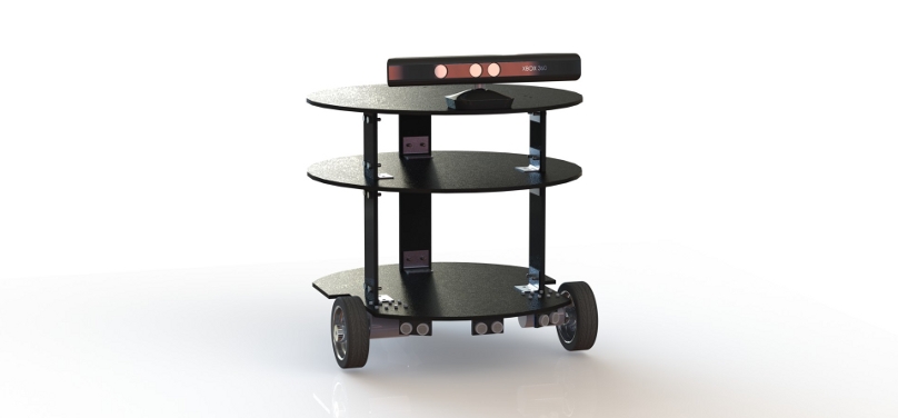
Good afternoon, Habr. Our team is developing a service robot Tod. We are committed to creating a multifunctional robot, which in its capabilities will be able to contend with such flagships in mobile robotics like PR2 Willow Garage. We start small, but every day our robot acquires new skills and is equipped with new sensors. You can find out what service robots are all about in our previous article , and today we’ll talk about the implementation of the Tod navigation system. Today we will tell you how to teach a robot to perform the navigation task of determining its own location based on wheel odometry and to obtain sensory data from ultrasonic sonars. The whole thing will be managed under the operating system for robots ROS (Robot Operating System), which is well established in various robotic projects. Welcome under cat.
At the average person, the word “robot” is most likely associated with smart humanoid robots from science fiction films in the spirit of the Terminator. What is the difference between real robots and ordinary cars? First of all, robots have autonomy, which is expressed in the ability to make decisions independently, without human intervention.
Autonomous robot to achieve the goal should be able to solve navigation problems. The basic navigation tasks include environmental perception based on the interpretation of data from different types of sensors (range finders, cameras, GPS navigators, special beacons, etc.), route planning and interactive interaction with the environment with the help of executive bodies , wheels and manipulators.
The basis of high-quality navigation algorithms is complex mathematics, so many novice robotics lose their enthusiasm after a collision with the calculations of Jacobians and quaternions, building a kinematic model and using probabilistic algorithms. Fortunately, today there are many robotic frameworks such as ROS, Player and Microsoft Robotics Studio, with which even beginners with the necessary perseverance can use sophisticated navigation and AI algorithms in their projects.
ROS and navigation stack
It was no coincidence that our team decided to use the open source framework Robot Operating System for Tod. ROS today is used in robotic projects of many research groups and companies. This framework provides capabilities comparable to the functions of the entire OS, including hardware abstractions, low-level device management, the implementation of basic functions and algorithms, interprocess communication, and the package manager. The program executed in ROS is a set of nodes that can exchange messages with each other by subscribing to a common theme. Such nodes can be independently implemented in C ++ and Python. ROS is fully powered by Ubuntu, in particular, we use Tod Ubuntu 12.40 and ROS Groovy. More information on ROS, documentation and good walkthroughs can be found at ros.org.
To solve navigation problems, ROS provides a navigation stack. The stack uses the odometer data (the distance traveled by the wheels of the robot) and sensors as input data, and the output transmits commands for controlling the speed of movement to the robot. Using the out-of-the-box navigation stack on a robot becomes possible when certain conditions are met:
- The robot must be round or rectangular in shape, and its wheels must be non-holonomic, i.e. The movement of the robot should be carried out only along the direction of rotation of the wheels. For example, the wheels of a car or a bicycle are nonholonomic.
- The robot must provide information about all the geometric connections between the kinematic nodes and the sensors of the robot. This information is specified in the URDF model, and complex geometric transformations from one coordinate system to another using the rotation matrices, Euler angles, and quaternions can be performed by the tf node.
- The robot must send messages to control the movement in the format of linear and angular velocity.
- A laser range finder or a 3-D scanner should be used for solving location and mapping tasks. However, if you cheat a little, you can use other cheaper counterparts instead of expensive sensors: sonars or infrared rangefinders. In this case, the main thing is to observe the correct format of messages that are transmitted to the executable node.
')
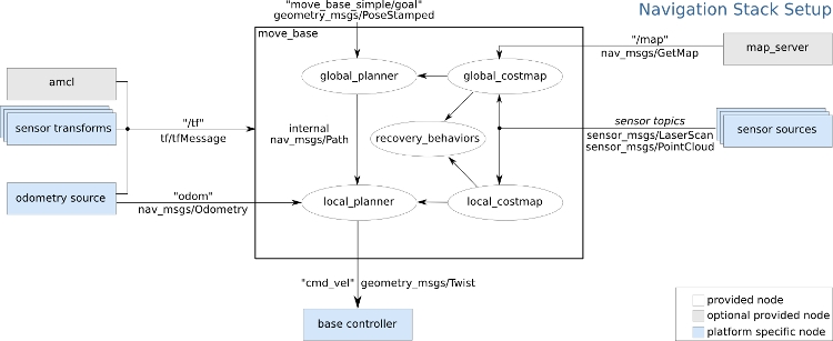
The diagram shows the general layout of the navigation stack. The text between the arrows indicates the type of message that the nodes exchange. In this stack there are 3 types of nodes:
- Nodes placed in a white rectangle are provided by ROS
- Nodes placed in gray rectangles are also provided by ROS, but their use in the stack is optional
- Nodes placed in turquoise rectangles are device-dependent and their implementation usually lies on the shoulders of the developer.
Now that the requirements for using the ROS navigation stack are known, we can begin to adapt it to our Tod robot.
Base controller and motion control
The base controller is the node of the navigation stack, which is responsible for controlling the movement of the robot. ROS does not provide a standard base controller, so for your robot you need to write your own node or use third-party open source solutions as a basis. The robot motion control commands are transmitted to the base controller in the cmd_vel thread in messages of the geometry_msgs / Twist type.
geometry_msgs/Vector3 linear float64 x float64 y float64 z geometry_msgs/Vector3 angular float64 x float64 y float64 z The linear vector specifies the linear velocity of the robot moving along the x, y, z axes, and the angular vector specifies the angular velocity of moving along the x, y, z axes. Further, these commands are converted into engine rotation control commands, and the robot moves in a given direction.
The order of the velocity vectors depends on the kinematics of the robot. Our Tod robot is equipped with a two-wheel differential drive based on DC motors, which allows it to move forward, backward, in an arc or rotate in place. This means that in the geometry_msgs / Twist message, only the linear velocity along the x axis (corresponding to the back and forth motion) and the angular velocity z (corresponding to rotation in place or moving along the arc when specifying a non-zero linear velocity) will be specified.
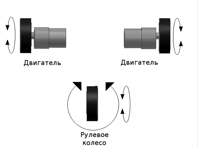
3-wheeled robot with differential drive. Steering wheel or ball bearing provides stability to the robot.
Converting these robot movement speeds to the corresponding engine rotation speeds is a trivial kinematics problem that requires some geometric calculations.
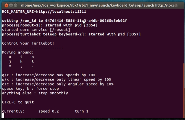
We assigned Arduino Uno a low-level engine rotation control task in conjunction with the Pololu Dual MC33926 Motor Driver Shield driver, delivering the required power to our 12 volt motors. After implementing the base controller, you can go through the robot using the keyboard and the ROS node of the turtlebot_teleop, sending geometry_msgs / Twist base controller messages.
Odometry
Odometry - the most common method of calculating the path. The essence of this method is to determine the position of the robot based on the calculation of the incremental wheel rotation relative to any fixed point on the map. Usually, odometer measurements are made by optical digital encoders mounted on wheels or directly on the engines of a robot. Tod is equipped with digital encoders with a resolution of 64 pulses per revolution of the motor shaft, which corresponds to 8384 pulses per revolution of the wheel.
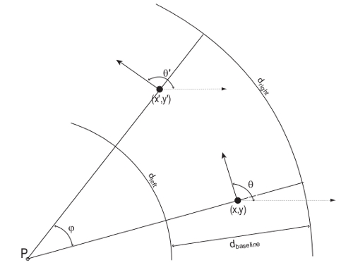
Odometry geometry. For a given position of the robot (x, y, theta) and the width of the wheelbase dbaseline, a new position (x ', y', theta ') must be calculated.
The navigation stack uses messages like nav_msgs / Odometry to retrieve odometer data.
std_msgs/Header header uint32 seq time stamp string frame_id string child_frame_id geometry_msgs/PoseWithCovariance pose geometry_msgs/Pose pose geometry_msgs/Point position float64 x float64 y float64 z geometry_msgs/Quaternion orientation float64 x float64 y float64 z float64 w float64[36] covariance geometry_msgs/TwistWithCovariance twist geometry_msgs/Twist twist geometry_msgs/Vector3 linear float64 x float64 y float64 z geometry_msgs/Vector3 angular float64 x float64 y float64 z float64[36] covariance The geometry_msgs / Pose message determines the current position of the robot in three-dimensional space and the orientation, which, in the case of an object rotating in three-dimensional space, will be conveniently calculated by quaternions. The geometry_msgs / Twist message already familiar to us determines the linear velocity x and the angular velocity z.
Since when performing calculations we deal with several coordinate systems, we need the node tf. The tf node, working with the robot's URDF model, takes care of the cumbersome calculations of converting the position from the robot's local coordinate system to the global coordinate system of the map.
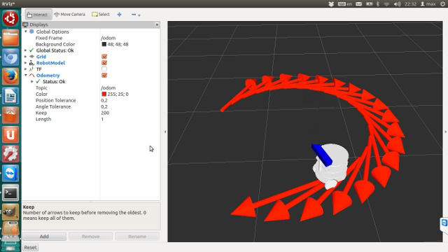
Visualization of the Tod URDF model with the odometry data in the Rviz simulator.
Sonar
The robot can use various types of sensors to obtain information about the world. Sensors vary greatly in their characteristics, have their limitations, weaknesses and strengths, so the joint use of several types of them is considered the most beneficial.
Using ultrasound sonars you can measure the distance from the object to the robot. Sonars work on TOF technology (time-of-flight). They emit a sound signal, which is reflected from the nearest object in the path and returns as an echo. The time of the “flight” of the signal is fixed, and on its basis the distance to the object is calculated.
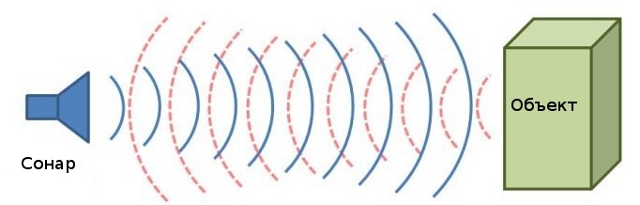
Sonar emits a beep and “listens” to the echo.
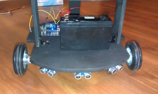
Tod uses HC-SR04 sonars that support a measurement range from 0.2 to 5 m with a declared accuracy of 0.03 m. The viewing angle of a single HC-SR04 is 30 degrees, and if you place several sonars side by side, you can get a larger viewing angle. 3 sonars placed on the front of the Tod provide a viewing angle of 90 degrees.
The ROS navigation stack can use data from various types of sensors to obtain odometry, build a room map, or avoid obstacles. Theoretically, it is possible to use sonars for building a room map, because 12 or more sonars give a viewing angle of 360 degrees and represent a cheaper replacement for expensive laser range finders. Tod uses the Kinect to build the map, which is superior to sonar in many sensory characteristics. However, this is not a reason to drop sonars from the account. Kinect is fixed on the robot high enough that it does not allow to see what is happening right under the wheels. Sonars capture this blind zone, thus proving useful in solving the problems of path planning and avoiding obstacles.
As mentioned earlier, the navigation stack only supports work with a laser sensor and a 3-D scanner. This limitation can be circumvented by presenting the sonar system as a fake 3-D scanner. The 3-D scanner uses a sensor_msgs / PointCloud message that describes a point cloud in three-dimensional space.
std_msgs/Header header uint32 seq time stamp string frame_id geometry_msgs/Point32[] points float32 x float32 y float32 z sensor_msgs/ChannelFloat32[] channels string name float32[] values Sensory sonar data can be represented in this format by setting each point of the cloud in the form of x, y coordinates and z coordinates equal to 0. At the same time, several such points can be set for each sonar, which makes it possible to increase the density of the cloud. Here is the visualization of the sensory data of the Tod sonar.
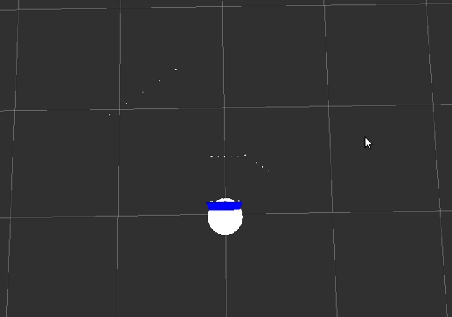
Visualize sonar sensory data in Rviz.
Thank you for your attention, that's all for today. In the next article we will continue to talk about the capabilities of the ROS navigation stack using the example of our test subject: connect to Tod Kinect, build an apartment map with it, teach you how to plan a route, and go around obstacles.
Source: https://habr.com/ru/post/204250/
All Articles