Pump controller
Good day to all! I want to share with you a simple controller for a water tank pump, which can be useful in any household.
')
1. How it works.
Initially, the plan was very simple - the controller must control the pump and ensure that the water in the tank does not fall below a predetermined level. Two sensors are used to control the water level. One sets the desired minimum level in the tank, and the second - the maximum. Later it was decided to add another sensor - emergency, which is located above the maximum. I also wanted the pump not to work on the principle of a cistern with water from the toilet bowl. This means that the pump should turn on only when the water level drops below the minimum and fill it to the maximum level. And then again wait until the water drops below the minimum level, so that the pump can be turned on again. To control the pump, we will use relays with normally open contacts, which should include a pump starter coil. Also added additional protection in the form of a mechanical float with a microswitch that is connected to the open circuit of the power supply of the relay coil. Instead, you can put a simple jumper.
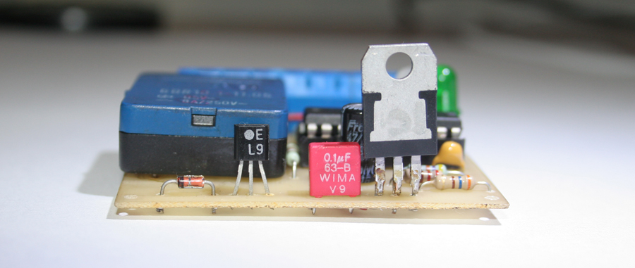
There are two LEDs. Green - the operation indicator and red - lights up when the pump is running, if the emergency sensor has triggered - blinks quickly.
2. Schematic diagram.
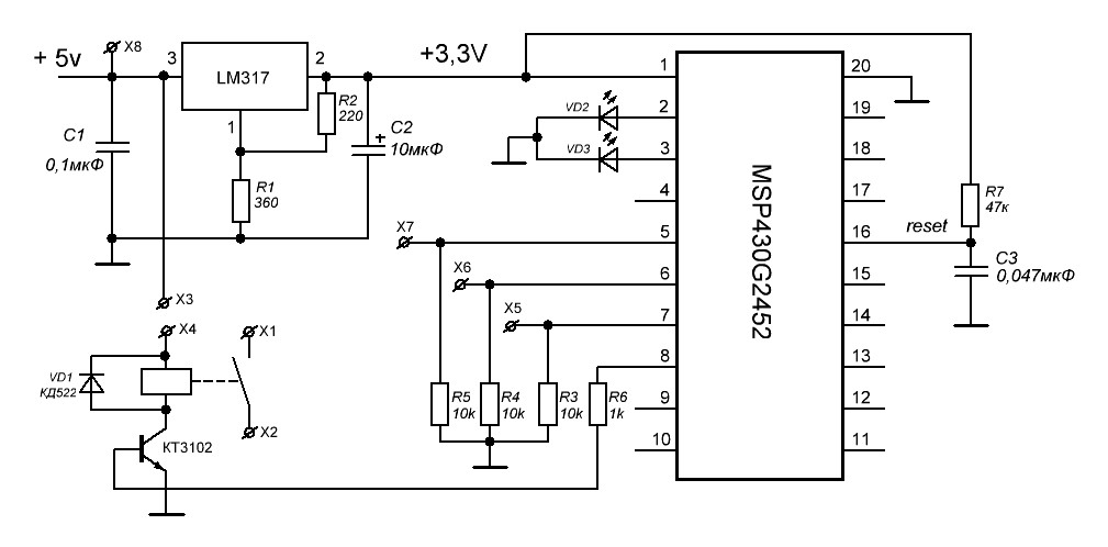
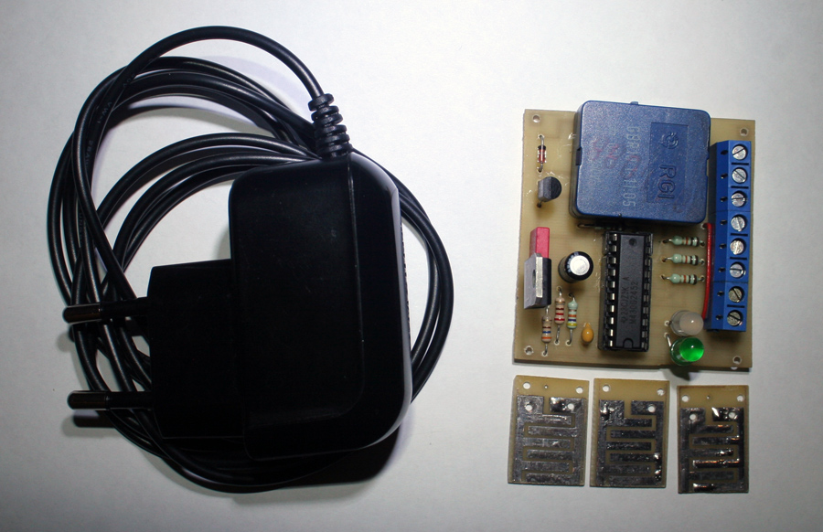
To control the pump and control the water level, we will use MSP430G2452 or MSP430G2553 (but the latter can be used as it is a pity because the younger controller can cope with the task). As a power source, use the charger from the phone at the output of which is an honest 5 volts. This is very important, since the use of another voltage entails a change in the values of the pull-up resistors at the controller inputs to which the water level sensors are connected. For stable operation, it is necessary that a stable high level be received at the input, which the controller defines as a logical "1" (preferably not less than 2.5 V) in the case of power supply from 5 volts, the voltage "1" is about 3.2 volts, so if the power supply is more 5 volts at the input will come over 3.3 volts, which can damage the controller. In the latter case, it is necessary to reduce the values of R3-R5 until the input voltage is in the range from 2.5V to 3.3V. And to get 3.3 Volts, we use LM317 to power the controller.
Sensors are two contacts with a minimum distance between them. Connected as follows +5 volts - common to all sensors and connected to one contact, and the second contact is connected to the corresponding inputs on the controller. When they are closed by water, a logical “1” appears on the controller.
3. Controller firmware
The program of the controller is written in IDE Energia, so the program can be easily adapted to any Arduino controller simply by rewriting the inputs and outputs to your controller, and the scheme is almost unchanged.
Controller firmware
// Pump control for water tank
// Two sensors are used: minimum and maximum water values
// And an emergency sensor located above the other two
// Work algorithm
// 1. Initially, the tank is empty
// 2. We start to fill the water to the maximum level and turn off the pump
// 3. The pump is turned off until the water drops below the minimum level.
// 4. Fill the tank until we reach the maximum level
// 5. If the water reaches the emergency sensor, the pump is turned off
int minim = 5; // pin minimum level
int maxim = 6; // pin maximum level
int maxstop = 7; // emergency pin
int realay = 8; // pin relay
int led = 3; // pin of the LED when the relay is on
int x = 1; // variable, if x = 1 fill the tank if x = 0 - empty
int mi = 0;
int ma = 0;
int ms = 0;
int ledon = 2; // LED - controller operation indicator
void setup ()
{
pinMode (realay, OUTPUT);
pinMode (led, OUTPUT);
pinMode (ledon, OUTPUT);
pinMode (minim, INPUT);
pinMode (maxim, INPUT);
pinMode (maxstop, INPUT);
digitalWrite (ledon, HIGH);
}
void loop ()
{
mi = digitalRead (minim); // read the values from the sensors
ma = digitalRead (maxim); // minimum and maximum values
ms = digitalRead (maxstop); // emergency sensor
if (ms == HIGH) // If the water has reached the emergency sensor, then turn off the pump and blink the led about the accident
{
digitalWrite (realay, LOW);
digitalWrite (led, LOW);
delay (200);
digitalWrite (led, HIGH);
delay (200);
}
else // otherwise we work in normal mode
{
if (mi == LOW && ma == LOW) // If less than the minimum value, then turn on the pump
{
digitalWrite (realay, HIGH);
digitalWrite (led, HIGH);
x = 1;
}
if (mi == HIGH && ma == HIGH) // If the maximum level, then turn off the pump
{
digitalWrite (realay, LOW);
digitalWrite (led, LOW);
x = 0;
}
if (mi == HIGH && ma == LOW && x == 1) // fill with water
{
digitalWrite (realay, HIGH);
digitalWrite (led, HIGH);
}
if (mi == HIGH && ma == LOW && x == 0) // empty the capacity
{
digitalWrite (realay, LOW);
digitalWrite (led, LOW);
}
}
}
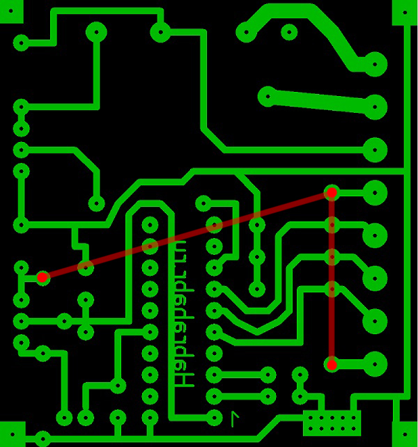
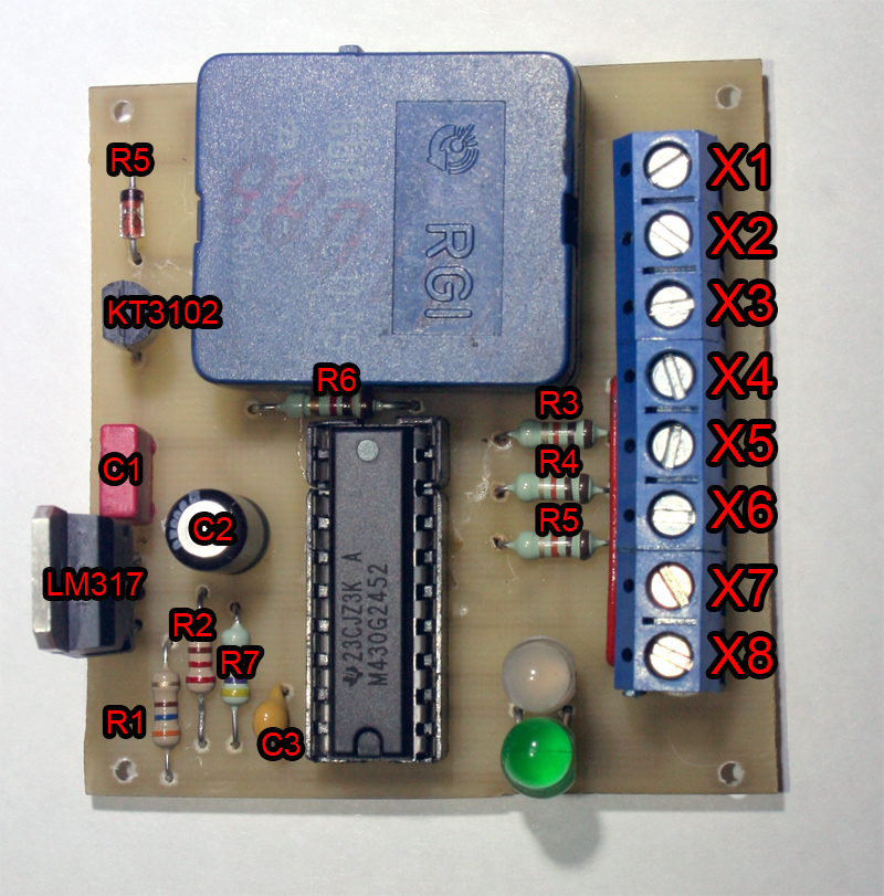
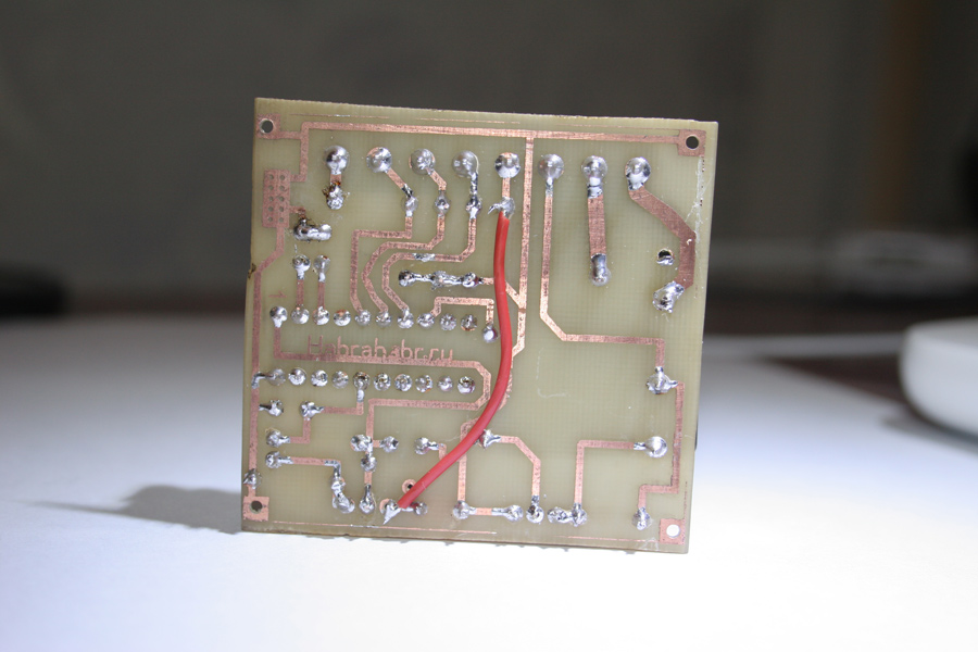
4. PCB
The fee is divorced taking into account the available parts and is made according to the popular LUT technology. Please note that in my motherboard you need to install two jumpers.
At the moment there is a very important point. How long will water sensors last? I mean, will they corrode and how will it affect their work? Maybe someone knows the answer to this question.
You can download the archive with the firmware, board files and sensors here. ARCHIVE
That's all! Thanks to all.
Source: https://habr.com/ru/post/204156/
All Articles