How to make sure that the flash drive works in USB 3.0?
In the modern IT industry it often happens that the assurances of the device manufacturer regarding its functionality are not true. From skepticism about this, let's move on to solving a specific technical problem ...
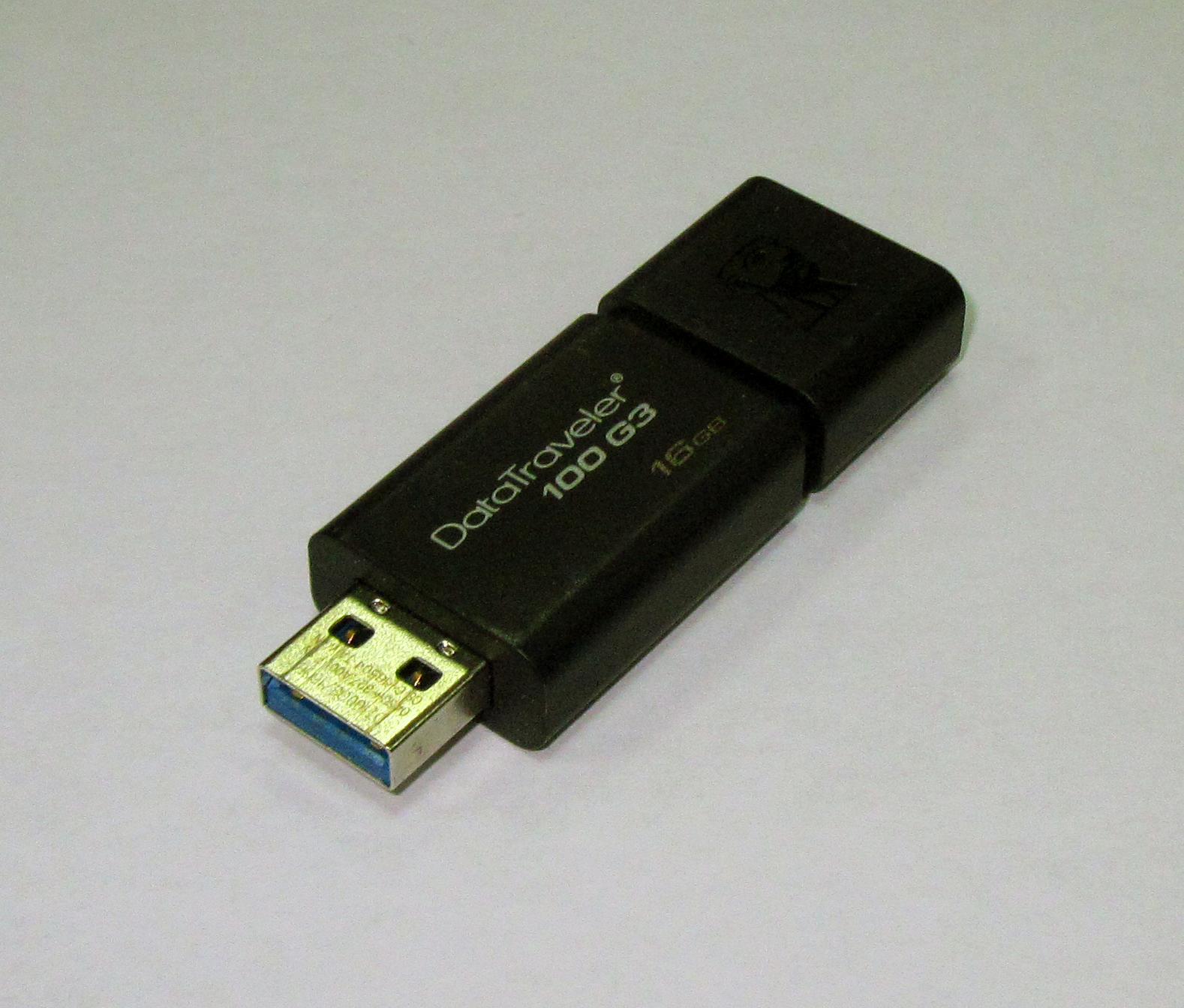
In our lab it turned out to be USB flash drive Kingston DataTraveler 3.0 . According to the manufacturer, the device supports USB 3.0. Check if this is in fact, without disassembling the flash drive and without violating the warranty.
Looking closely at the connector, behind the four " near " contacts that support USB 2.0, we, as expected, found five " long-range " contacts that are used only in USB 3.0 Super Speed mode. We measure the resistance of USB 3.0 signal lines relative to the earth, we get values other than infinity. Conclusion: USB 3.0 contacts are physically present and do not end in a dead end. The measurement was performed with an ohmmeter at the limit used to test semiconductor diodes. To access the “far” contacts of the USB 3.0 connector, you can construct an adapter or use a thin and long probe, such as a needle. The result is a necessary but not sufficient condition for the device to operate in USB 3.0 Super Speed mode. It may happen that the signal circuits end with terminating resistors, but are not connected to the controller. Therefore, we proceed to the next test - software.
')
The experiment is performed on a fairly new, still unexplored Tyan S5533 motherboard , built on the Denlow chipset .

Figure 1 . Tyan S5533 motherboard in ITX format
To eliminate the influence of drivers running in the operating system session, our test will be “extremely low-level”, we will run under DOS, and monitor the results by viewing the Memory Mapped I / O dump of the USB controller.
The sequence of actions is as follows.
1) Using the beta version of the USB Book Labs development utility USB.EXE , we determine the address of the block of configuration registers of the XHCI controller, in our example it is bus = 0, device = 14h, function = 0. We also define the base address of the operating register block in the Memory Mapped I / O space, in our example it is equal to F7500000h.

Figure 2 . The results of the utility USB.EXE. The address of the XHCI configuration register block: bus = 0, device = 14h, function = 0. The base address of the XHCI operating registers is F7500000h.
2) As is known, for compatibility with software that does not support a USB 3.0 XHCI controller, on this platform, by default, USB 3.0 ports are serviced by a USB 2.0 EHCI controller. Our task is to transfer them to the maintenance mode by the USB 3.0 XHCI controller. We use the documentation of the Intel 8 Series / C220 Series Chipset Family Platform Controller Hub Datasheet and any utility that allows you to edit the contents of the system logic registers.
We program the register USB 3.0 Port Routing Mask Register. We write to the address bus = 0, device = 14h, function = 0, register = 0DCh bytes with a value of 0FFh.
We program the register USB 3.0 Port Super Speed Enable Register. We write to the address bus = 0, device = 14h, function = 0, register = 0D8h bytes with a value of 0FFh.
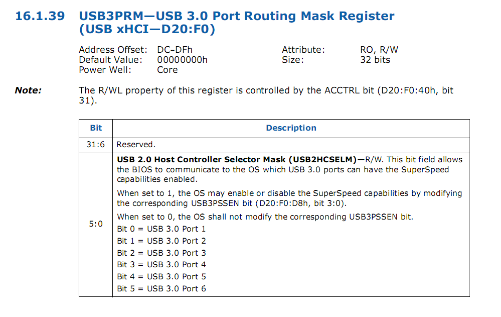
Fig.3 . Register USB 3.0 Port Routing Mask Register

Fig.4 . Register USB 3.0 Port Super Speed Enable Register
3) Read and decode according to Fig.5 and Fig.6 the initial state of several bit fields from the lower 16-bits of the 32-bit register PORTSCNUSB3 before connecting the device to the port under study. The register is located at offset 0570h from the base address of the block of operating registers of the controller, its address is F7500000h + 0570h = F7500570h
The read value = 02A0h = 00 00.00 10.1010.00 00 b
D0 = Current Connect Status = 0. The device is not connected.
D1 = Port Enabled / Disabled = 0. The port is not used.
D [13-10] = Port Speed = 0000b. Speed is not defined.
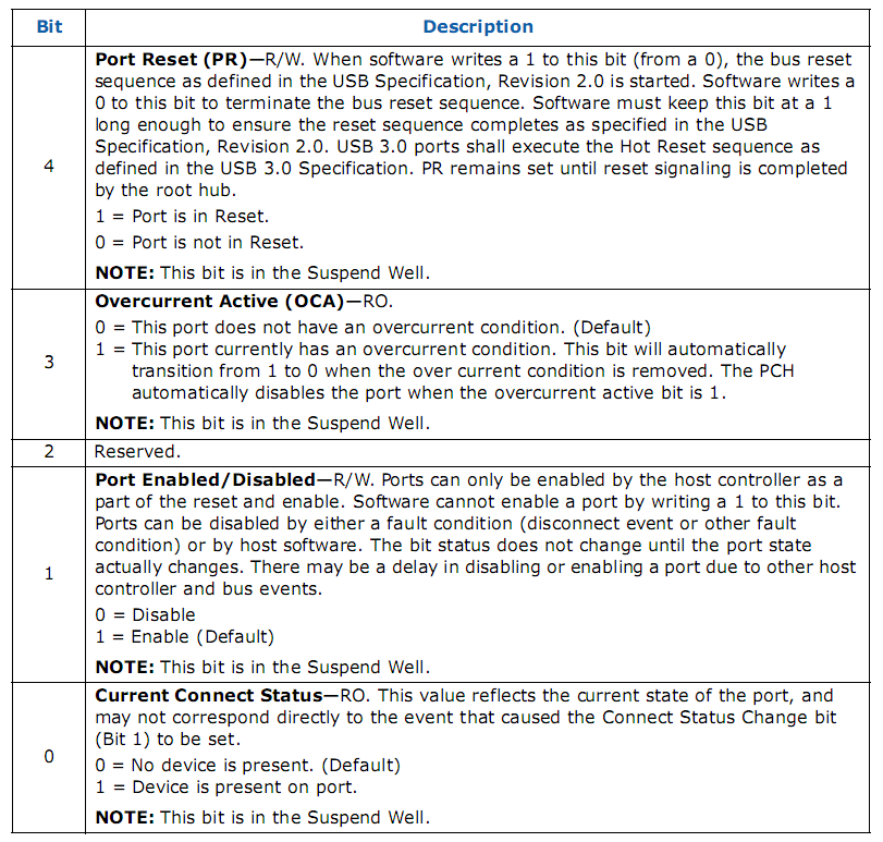
Fig.5 . USB 3.0 Port Status and Control Register, bits [4-0]
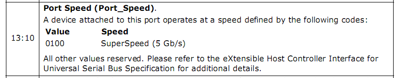
Fig.6 . USB 3.0 Port Status and Control Register, bits [13-10]
4) Connect a USB 3.0 flash drive, then reread the register and decrypt the same bit fields.
The read value = 1203h = 00 01.00 10.0000.00 11 b
D0 = Current Connect Status = 1. The device is connected.
D1 = Port Enabled / Disabled = 1. The port is in use.
D [13-10] = Port Speed = 0100b. The speed is 5.0 Gbit / S, USB 3.0 Super Speed mode works.
5) For self-checking, we connect a USB 2.0 flash drive to the same port, then reread the register and decrypt the same bit fields. The read value = 02A0h, which corresponds to no connection. So it should be, the PORTSCNUSB3 register "does not see" the USB 2.0 device, since it is serviced by another subsystem and the connection status is available through another register - PORTSCNUSB2, consideration of which is beyond the scope of our research.
The test flash drive does support USB 3.0 mode .
If you formalize and program the described actions as a DOS program or a UEFI application, you will get a small utility that allows you to quickly determine in which speed mode the USB device works. To simplify our example, we implemented it for a particular case - the Tyan S5533 USB subsystem subsystem and the use of the first port, so the address of the PORTSCNUSB3 register in our example is constant. In general, in order for the program to work on all platforms, the address of the PORTSCNUSB3 register must be calculated based on the contents of the XHCI Capabilities fields, in accordance with the USB 3.0 XHCI specification. On the other hand, universality can be achieved much simpler and more elegant using UEFI protocols instead of direct interaction with controller registers.
As the "guinea pig" was used device Kingston DataTraveler 100 G3, 16 GB:
1. Device descriptors that can be viewed using various information utilities indicate the potential capabilities of the device. The speed mode set for the USB port when the device is connected does not always correspond to the capabilities declared in the descriptors.
A device declaring USB 3.0 support may operate in USB 2.0 mode due to manufacturing faults, a faulty cable, and many other reasons. At the same time, the contents of the descriptors may indicate support for USB 3.0 mode.
The USB specification recommends that the device issue a different set of descriptors depending on the actual set speed. But we have no guarantee that this recommendation is observed by the developers of the flash drive.
Of course, the contents of the device descriptors are a more reliable source of information than the inscription on the flash drive and the vows of the seller. But for the reasons stated above, confidence is different from 100 percent.
It is the desire to bring the accuracy to 100% led us to extremely low-level research.
2. Another method is to track in the device manager which controller is the parent of a flash drive (USB 2.0 EHCI or USB 3.0 XHCI) is also inefficient, since, according to the specification, the USB 3.0 XHCI controller can support all kinds of devices: from Low-Speed to Super Speed. Therefore, from the fact that for a flash drive the parent controller is xHCI, it does not follow that the device operates in Super Speed mode.
Formulation of the problem
In our lab it turned out to be USB flash drive Kingston DataTraveler 3.0 . According to the manufacturer, the device supports USB 3.0. Check if this is in fact, without disassembling the flash drive and without violating the warranty.
Hardware test
Looking closely at the connector, behind the four " near " contacts that support USB 2.0, we, as expected, found five " long-range " contacts that are used only in USB 3.0 Super Speed mode. We measure the resistance of USB 3.0 signal lines relative to the earth, we get values other than infinity. Conclusion: USB 3.0 contacts are physically present and do not end in a dead end. The measurement was performed with an ohmmeter at the limit used to test semiconductor diodes. To access the “far” contacts of the USB 3.0 connector, you can construct an adapter or use a thin and long probe, such as a needle. The result is a necessary but not sufficient condition for the device to operate in USB 3.0 Super Speed mode. It may happen that the signal circuits end with terminating resistors, but are not connected to the controller. Therefore, we proceed to the next test - software.
')
Software test
The experiment is performed on a fairly new, still unexplored Tyan S5533 motherboard , built on the Denlow chipset .
Figure 1 . Tyan S5533 motherboard in ITX format
To eliminate the influence of drivers running in the operating system session, our test will be “extremely low-level”, we will run under DOS, and monitor the results by viewing the Memory Mapped I / O dump of the USB controller.
The sequence of actions is as follows.
1) Using the beta version of the USB Book Labs development utility USB.EXE , we determine the address of the block of configuration registers of the XHCI controller, in our example it is bus = 0, device = 14h, function = 0. We also define the base address of the operating register block in the Memory Mapped I / O space, in our example it is equal to F7500000h.
Figure 2 . The results of the utility USB.EXE. The address of the XHCI configuration register block: bus = 0, device = 14h, function = 0. The base address of the XHCI operating registers is F7500000h.
2) As is known, for compatibility with software that does not support a USB 3.0 XHCI controller, on this platform, by default, USB 3.0 ports are serviced by a USB 2.0 EHCI controller. Our task is to transfer them to the maintenance mode by the USB 3.0 XHCI controller. We use the documentation of the Intel 8 Series / C220 Series Chipset Family Platform Controller Hub Datasheet and any utility that allows you to edit the contents of the system logic registers.
We program the register USB 3.0 Port Routing Mask Register. We write to the address bus = 0, device = 14h, function = 0, register = 0DCh bytes with a value of 0FFh.
We program the register USB 3.0 Port Super Speed Enable Register. We write to the address bus = 0, device = 14h, function = 0, register = 0D8h bytes with a value of 0FFh.
Fig.3 . Register USB 3.0 Port Routing Mask Register
Fig.4 . Register USB 3.0 Port Super Speed Enable Register
3) Read and decode according to Fig.5 and Fig.6 the initial state of several bit fields from the lower 16-bits of the 32-bit register PORTSCNUSB3 before connecting the device to the port under study. The register is located at offset 0570h from the base address of the block of operating registers of the controller, its address is F7500000h + 0570h = F7500570h
The read value = 02A0h = 00 00.00 10.1010.00 00 b
D0 = Current Connect Status = 0. The device is not connected.
D1 = Port Enabled / Disabled = 0. The port is not used.
D [13-10] = Port Speed = 0000b. Speed is not defined.
Fig.5 . USB 3.0 Port Status and Control Register, bits [4-0]
Fig.6 . USB 3.0 Port Status and Control Register, bits [13-10]
4) Connect a USB 3.0 flash drive, then reread the register and decrypt the same bit fields.
The read value = 1203h = 00 01.00 10.0000.00 11 b
D0 = Current Connect Status = 1. The device is connected.
D1 = Port Enabled / Disabled = 1. The port is in use.
D [13-10] = Port Speed = 0100b. The speed is 5.0 Gbit / S, USB 3.0 Super Speed mode works.
5) For self-checking, we connect a USB 2.0 flash drive to the same port, then reread the register and decrypt the same bit fields. The read value = 02A0h, which corresponds to no connection. So it should be, the PORTSCNUSB3 register "does not see" the USB 2.0 device, since it is serviced by another subsystem and the connection status is available through another register - PORTSCNUSB2, consideration of which is beyond the scope of our research.
Summary
The test flash drive does support USB 3.0 mode .
If you formalize and program the described actions as a DOS program or a UEFI application, you will get a small utility that allows you to quickly determine in which speed mode the USB device works. To simplify our example, we implemented it for a particular case - the Tyan S5533 USB subsystem subsystem and the use of the first port, so the address of the PORTSCNUSB3 register in our example is constant. In general, in order for the program to work on all platforms, the address of the PORTSCNUSB3 register must be calculated based on the contents of the XHCI Capabilities fields, in accordance with the USB 3.0 XHCI specification. On the other hand, universality can be achieved much simpler and more elegant using UEFI protocols instead of direct interaction with controller registers.
Information sources
UPD
As the "guinea pig" was used device Kingston DataTraveler 100 G3, 16 GB:
UPD-II
1. Device descriptors that can be viewed using various information utilities indicate the potential capabilities of the device. The speed mode set for the USB port when the device is connected does not always correspond to the capabilities declared in the descriptors.
A device declaring USB 3.0 support may operate in USB 2.0 mode due to manufacturing faults, a faulty cable, and many other reasons. At the same time, the contents of the descriptors may indicate support for USB 3.0 mode.
The USB specification recommends that the device issue a different set of descriptors depending on the actual set speed. But we have no guarantee that this recommendation is observed by the developers of the flash drive.
Of course, the contents of the device descriptors are a more reliable source of information than the inscription on the flash drive and the vows of the seller. But for the reasons stated above, confidence is different from 100 percent.
It is the desire to bring the accuracy to 100% led us to extremely low-level research.
2. Another method is to track in the device manager which controller is the parent of a flash drive (USB 2.0 EHCI or USB 3.0 XHCI) is also inefficient, since, according to the specification, the USB 3.0 XHCI controller can support all kinds of devices: from Low-Speed to Super Speed. Therefore, from the fact that for a flash drive the parent controller is xHCI, it does not follow that the device operates in Super Speed mode.
Source: https://habr.com/ru/post/204078/
All Articles