Technical report on the development of the contactless charging system for mobile devices "Powell"
In connection with numerous requests for technical details of the development of a contactless charging system for mobile devices, dubbed “Powell,” we decided to make a somewhat more detailed report on the progress of the development itself. We remind that the main goal of the project was to develop a resonant contactless power supply system, which could be used to power any electronic devices: mobile phones, MP3 players, digital cameras, GPS navigators, D / U remotes, car accessories, medical equipment, and more. .d

Introduction
The use of contactless power systems will make consumer electronics more reliable and easy to use [1-2]. The additional possibility of transmitting information in contactless power supply systems can provide detection and identification of devices, and also allows one to determine the relative position of devices during operation. In the absence of receivers in the range of the transmitter, there is no need for the transmitter to emit the MHz signal of a high frequency band (up to 10 W), which will save energy consumed by the device. It is also desirable to transmit information about the level of the received MHz signal (the distance between the receiver and the transmitter) and the number of receiving devices in order to establish the necessary radiation power of the MHz signal. Device identification is necessary in many areas where aspects such as security and privacy are important.
Wireless data sharing with wireless power transmission
To transmit information via a communication channel, a digital message, which is a sequence of characters, must be converted into an analog signal — a time-varying voltage level. The specified conversion is performed by modulation. The reverse process is called demodulation.
Today, systems of joint wireless transmission of energy and information using a resonator tuned to one operating frequency [4, 5] are known. In [4], the possibility of realizing a receiver of information and energy using an amplitude-modulated signal using a single antenna is shown. The system of joint wireless transmission of energy and information, described in [5], operates at a frequency of 13.56 MHz and allows you to simultaneously transmit energy with an efficiency of 50% and data at speeds up to 1 Mbit / s. The basis of the principle of operation is the modulation of the carrier frequency information signal.
However, when using this method of joint wireless transmission of data and energy, the energy transfer efficiency decreases, since the average power of the amplitude-modulated signal is less than the unmodulated one. Another disadvantage of this method is the unrealizability of the simultaneous transmission of information from the receiver to the transmitter when receiving energy at the receiving resonator, using a single resonator operating on only one frequency.
In [6-8], contactless energy and data transfer systems are considered, in which the transmission is carried out using two pairs of resonators through their interaction in a near electromagnetic field.
The main elements of this system are receiving and transmitting resonators, which are multi-turn coils in the form of rings (Figure 1). Energy is transmitted at a frequency of about 150 kHz, that is, the relationship between the resonators is provided by means of a magnetic field. A solution was proposed based on the use of several frames differing in shape. In this case, the mutual coupling between the resonators used to transfer energy and information is minimized.
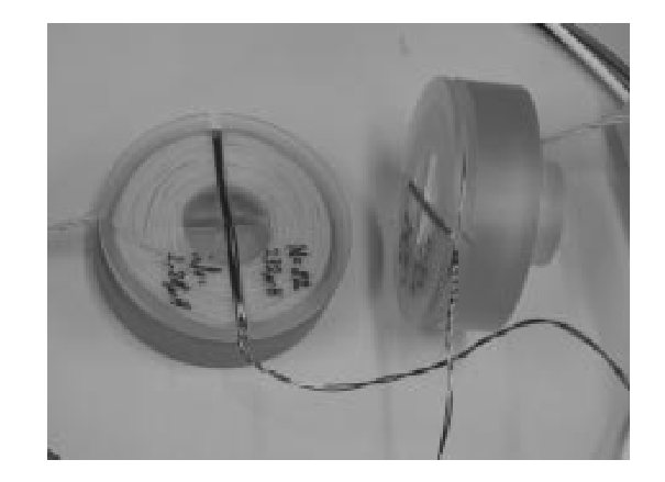
Figure 1 - Photo of the receiving and transmitting resonators
In the above systems, the transmission of energy and information was carried out through interaction in the near electromagnetic field. However, it was found that such systems have a number of disadvantages. The speed of data exchange and the efficiency of energy transfer are limited, moreover, the design of resonators is complicated by the fact that their designs must provide a sufficient isolation between energy and information transfer systems.
Such difficulties can be avoided if information is transmitted at much higher frequencies (for example, in standard RFID or Wi-Fi bands around 900 MHz and 2.4 GHz). The use of higher frequencies will significantly increase the speed of data transmission, as well as reduce the level of noise introduced by the energy transfer system.
Such solutions are well known and used in mobile phones. Wireless charging [9] or data transfer [10] is carried out using a separate resonator operating in the megahertz range. And at the same time, using separate antennas (GSM, Wi-Fi, etc.) data is exchanged.
However, the use of separate antennas for transmitting data and energy requires additional space, which is very limited in modern portable devices. This problem can be solved by using only one resonator, which operates in two frequency ranges - MHz and GHz. Frequency separation of channels for the transmission of energy and information is carried out using a diplexer.
')
Dual-band resonator for data transmission in conjunction with contactless energy transfer
Using the megahertz (MHz) band for energy transfer and the gigahertz (GHz) band for data exchange allows for a sufficient isolation between the systems and significantly increases the data transfer rate.
The complexity of the system due to the transmission of data and energy using a single resonator reduces its dimensions, but creates additional difficulties due to the need to design a two-mode resonator with matching circuits and a diplexer for the subsequent separation of channels. Since the working frequencies of the resonator are far apart, it is advisable to use the simplest low and high pass filters as a diplexer.
As a transmitting and receiving resonators, it was decided to use a design with high efficiency for energy transfer (EFFICIENCY), which, in addition, can be effectively used as a receiving and transmitting antenna in the gigahertz frequency range.
The design of the resonator was performed using electrodynamic modeling.
An example of the design of the resonator is presented in Figure 2.
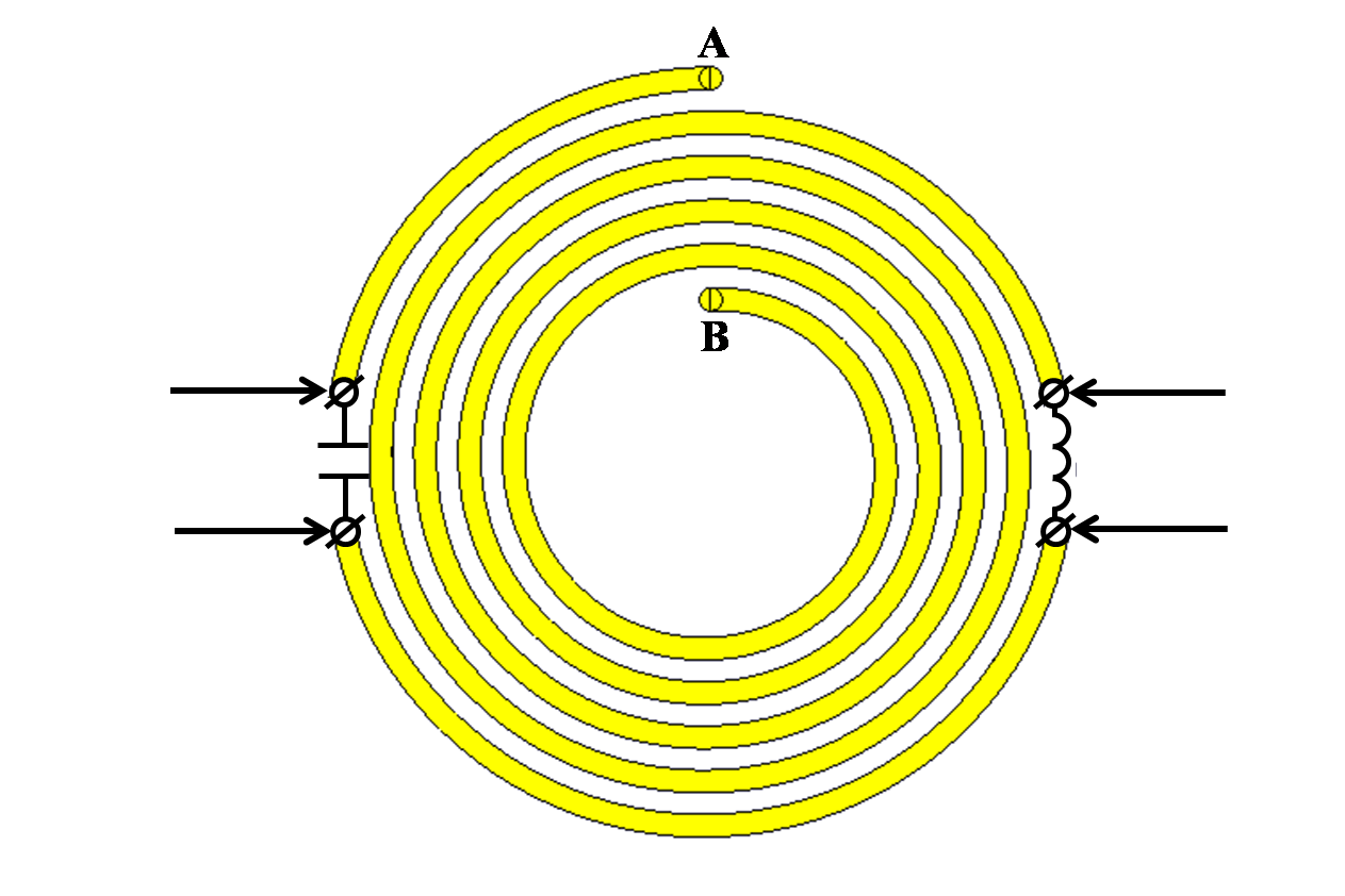
Figure 2 - The design of the resonator with N = 5, operating in two ranges.
In the spiral, cuts are made symmetrically, at the ends of which contact pads are made. Between the contact pads are installed inductance L0 and capacitor C0. Inductance at a low frequency is equivalent to a short circuit, and capacitance is idle. At high frequency, the inductance is equivalent to idling, and the capacitance is short circuit.
As we see, in the proposed design of the resonator at each operating frequency, both channels do not affect each other, since they are “shorted” at the operating frequency of the other channel. This approach allows you to design the circuit input channels independently of each other.
Production of experimental samples of receiving and transmitting resonators
Then the topologies of the receiving and transmitting resonators with matching circuits were proposed (Figure 3) [11].
The red lines correspond to the metallization of the upper layer of the printed circuit board, the green lines to the metallization of the lower layer, and the blue lines to the borders of the printed circuit boards. Gray pads are contact pads for surface-mounted components and connectors located in the top layer.
The resonators are located on a dielectric substrate. FR4 was selected as the substrate material.
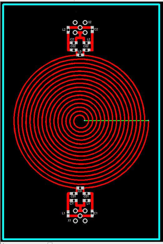
Figure 3 - Topology of the transmitting resonator.
Experimental testing of a wireless power transmission system along with information transfer
After installing the elements of the matching circuits in each resonator, experimental testing of the wireless power transmission system was performed along with the data transfer. The complex reflection coefficients in each channel of the resonators were measured, as well as the transmission coefficients for each channel of the system using an Agilent E5071C vector network analyzer.
The measured frequency dependences of the reflection coefficients of the receiving resonator in the two ranges under study are presented in Fig. 4.
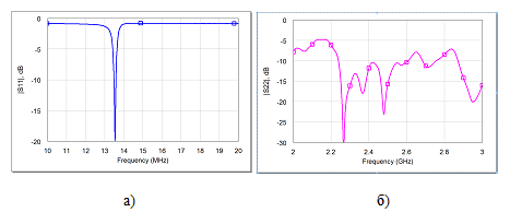
Figure 4 - The measured frequency dependences of the reflection coefficients of the receiving resonator a) at energy transmission frequencies, b) at information transmission frequencies.
A transmitting resonator was also investigated in two frequency ranges. The measured frequency dependences of the reflection coefficients of the transmitting resonator are presented in Fig. 5.

Figure 5 - The measured frequency dependences of the reflection coefficients of the transmitting resonator a) at energy transmission frequencies, b) at information transmission frequencies.
At the working frequencies in both channels of the receiving and transmitting resonators, the necessary level of matching (-10 dB) is achieved, which confirms the correctness of the calculation of the matching circuits (balanced transformers).
The results of measuring the transmission coefficient of the system are presented in Figure 6.
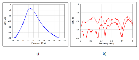
Figure 6 - The measured frequency dependences of the transmission coefficients of a system of two resonators, with a distance between the resonators of 1.5 cm (shown as a solid line), with a distance of 1 cm dotted.
The transmission coefficient in the data transmission channel at a frequency of 2.4 GHz lies above the level of -25 dB, which is more than enough for reliable reception of modern digital data transmission systems, since a much lower signal power of about 0 dBm (1 mW) is radiated during data transmission compared to power transmission (up to 10 W) and digital receivers have high sensitivity up to 80 dBm.
The measured value of the energy transfer rate of the system was -3 dB. It is worth noting that the level of coordination at a frequency of, for example, 13.56 MHz is about -10 dB, which meets the requirements. If you achieve a better match, allowing you to virtually eliminate the reflection loss, the efficiency will be at least 70% with a distance between the resonators no more than 1.5 cm.
A demonstration of the wireless charging system is shown in Figure 7. The harmonic signal from generator 1 is fed to the transmitting module 2. In the receiving module 3, a variable EMF is induced, which is rectified by the schottky diodes and powers the LED.
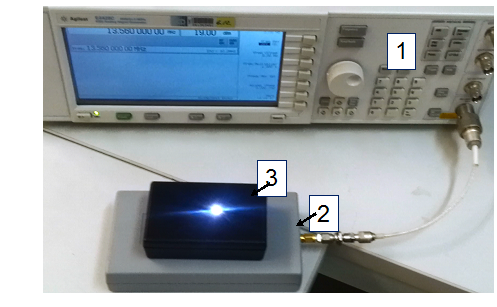
Figure 7 A photograph showing the operation of a wireless charging system using developed resonators.
There was also a demonstration of the work of the developed wireless charging system for application to commercial smartphones. Figure 8 shows the process of charging the smartphone Samsung Galaxy.

Figure 8 Photograph of a Samsung smartphone charging by a prototype of a contactless charging system.
Conclusion
At the development stage described in the article, the possibility of implementing data transmission in conjunction with contactless power transmission was investigated. According to the results of the study, a system was selected for further development of the technical solution, using one resonator for energy transfer and information exchange at two non-multiple operating frequencies, since this type of system has the smallest dimensions and provides a high data transfer rate.
For the implementation of data transfer simultaneously with contactless energy transfer, a two-band design of the receiving and transmitting resonators was developed. Electrical circuits were developed to match the input impedance of the resonators in the working ranges with the characteristic impedance of the supply lines. The proposed design of resonators eliminates the influence on each other of the channels for the transmission of energy and information.
Experimental resonator samples were made. As a result of measurements, the matching levels of the resonators were measured, as well as the system efficiency in two working ranges.
The development of an energy transmission system is ongoing, along with information transfer.
Report authors: development team.
Bibliography
[1] It makes it possible to ensure that everyday products are more convenient, reliable, and environmentally friendly, witricity.com.
[2] A.N. Didenko “Microwave Power Engineering: Theory and Practice”, Moscow: Nauka, 2003 - 446 p.
[3] Sklyar B. “Digital communication. Theoretical foundations and practical application ", Trans. from English - M .: Williams Publishing House, 2003 - 1098 c.
[4] Wu CT. M. A simple self-powered AM-demodulator for Wireless / Data Transmission / CT. M. Wu, JS Sun, and T. Itoh // Proc. of 42th European Microwave Conference - 2012 - P. 133-137.
[5] Hmida H. Ghairani and M. Samet Hmida GB Design of a Wireless Power and Data Transmission Circuits for Implantable Biomicrosystem / GB Hmida H. Ghairani and M. Samet // Biotechnology - 2007. - V.6 - P.153-164.
[6] Bieler T. Contactless Power and Information Transmission / T. Bieler, M. Perrottet, V. Nguyen, and Y. Perriard // IEEE Transactions on Industry Applications - 2002 - V.38 - N.5 - P.1266 - 1272.
[7] C. Rathge, D. Kuschner, // Proc. of 13th European Conference - Power Electronics and Applications - 2012 - P.1 - 8.
[8] M. Dionigi, M. Mongiardo, Proc. Workshop Technologies: Systems, and Applications (IMWS) - 2012 - P.61-64.
[9] Wireless Charging, www.nokia.com/ru-ru/products/wireless-charging
[10] Tushyushin T. Near European Communication Patent Application - 2008 - EP1976055.
[11] AVR2004: LC-Balun for AT86RF230. Atmel Application Note. July 2004.
Introduction
The use of contactless power systems will make consumer electronics more reliable and easy to use [1-2]. The additional possibility of transmitting information in contactless power supply systems can provide detection and identification of devices, and also allows one to determine the relative position of devices during operation. In the absence of receivers in the range of the transmitter, there is no need for the transmitter to emit the MHz signal of a high frequency band (up to 10 W), which will save energy consumed by the device. It is also desirable to transmit information about the level of the received MHz signal (the distance between the receiver and the transmitter) and the number of receiving devices in order to establish the necessary radiation power of the MHz signal. Device identification is necessary in many areas where aspects such as security and privacy are important.
Wireless data sharing with wireless power transmission
To transmit information via a communication channel, a digital message, which is a sequence of characters, must be converted into an analog signal — a time-varying voltage level. The specified conversion is performed by modulation. The reverse process is called demodulation.
Today, systems of joint wireless transmission of energy and information using a resonator tuned to one operating frequency [4, 5] are known. In [4], the possibility of realizing a receiver of information and energy using an amplitude-modulated signal using a single antenna is shown. The system of joint wireless transmission of energy and information, described in [5], operates at a frequency of 13.56 MHz and allows you to simultaneously transmit energy with an efficiency of 50% and data at speeds up to 1 Mbit / s. The basis of the principle of operation is the modulation of the carrier frequency information signal.
However, when using this method of joint wireless transmission of data and energy, the energy transfer efficiency decreases, since the average power of the amplitude-modulated signal is less than the unmodulated one. Another disadvantage of this method is the unrealizability of the simultaneous transmission of information from the receiver to the transmitter when receiving energy at the receiving resonator, using a single resonator operating on only one frequency.
In [6-8], contactless energy and data transfer systems are considered, in which the transmission is carried out using two pairs of resonators through their interaction in a near electromagnetic field.
The main elements of this system are receiving and transmitting resonators, which are multi-turn coils in the form of rings (Figure 1). Energy is transmitted at a frequency of about 150 kHz, that is, the relationship between the resonators is provided by means of a magnetic field. A solution was proposed based on the use of several frames differing in shape. In this case, the mutual coupling between the resonators used to transfer energy and information is minimized.
Figure 1 - Photo of the receiving and transmitting resonators
In the above systems, the transmission of energy and information was carried out through interaction in the near electromagnetic field. However, it was found that such systems have a number of disadvantages. The speed of data exchange and the efficiency of energy transfer are limited, moreover, the design of resonators is complicated by the fact that their designs must provide a sufficient isolation between energy and information transfer systems.
Such difficulties can be avoided if information is transmitted at much higher frequencies (for example, in standard RFID or Wi-Fi bands around 900 MHz and 2.4 GHz). The use of higher frequencies will significantly increase the speed of data transmission, as well as reduce the level of noise introduced by the energy transfer system.
Such solutions are well known and used in mobile phones. Wireless charging [9] or data transfer [10] is carried out using a separate resonator operating in the megahertz range. And at the same time, using separate antennas (GSM, Wi-Fi, etc.) data is exchanged.
However, the use of separate antennas for transmitting data and energy requires additional space, which is very limited in modern portable devices. This problem can be solved by using only one resonator, which operates in two frequency ranges - MHz and GHz. Frequency separation of channels for the transmission of energy and information is carried out using a diplexer.
')
Dual-band resonator for data transmission in conjunction with contactless energy transfer
Using the megahertz (MHz) band for energy transfer and the gigahertz (GHz) band for data exchange allows for a sufficient isolation between the systems and significantly increases the data transfer rate.
The complexity of the system due to the transmission of data and energy using a single resonator reduces its dimensions, but creates additional difficulties due to the need to design a two-mode resonator with matching circuits and a diplexer for the subsequent separation of channels. Since the working frequencies of the resonator are far apart, it is advisable to use the simplest low and high pass filters as a diplexer.
As a transmitting and receiving resonators, it was decided to use a design with high efficiency for energy transfer (EFFICIENCY), which, in addition, can be effectively used as a receiving and transmitting antenna in the gigahertz frequency range.
The design of the resonator was performed using electrodynamic modeling.
An example of the design of the resonator is presented in Figure 2.
Figure 2 - The design of the resonator with N = 5, operating in two ranges.
In the spiral, cuts are made symmetrically, at the ends of which contact pads are made. Between the contact pads are installed inductance L0 and capacitor C0. Inductance at a low frequency is equivalent to a short circuit, and capacitance is idle. At high frequency, the inductance is equivalent to idling, and the capacitance is short circuit.
As we see, in the proposed design of the resonator at each operating frequency, both channels do not affect each other, since they are “shorted” at the operating frequency of the other channel. This approach allows you to design the circuit input channels independently of each other.
Production of experimental samples of receiving and transmitting resonators
Then the topologies of the receiving and transmitting resonators with matching circuits were proposed (Figure 3) [11].
The red lines correspond to the metallization of the upper layer of the printed circuit board, the green lines to the metallization of the lower layer, and the blue lines to the borders of the printed circuit boards. Gray pads are contact pads for surface-mounted components and connectors located in the top layer.
The resonators are located on a dielectric substrate. FR4 was selected as the substrate material.
Figure 3 - Topology of the transmitting resonator.
Experimental testing of a wireless power transmission system along with information transfer
After installing the elements of the matching circuits in each resonator, experimental testing of the wireless power transmission system was performed along with the data transfer. The complex reflection coefficients in each channel of the resonators were measured, as well as the transmission coefficients for each channel of the system using an Agilent E5071C vector network analyzer.
The measured frequency dependences of the reflection coefficients of the receiving resonator in the two ranges under study are presented in Fig. 4.
Figure 4 - The measured frequency dependences of the reflection coefficients of the receiving resonator a) at energy transmission frequencies, b) at information transmission frequencies.
A transmitting resonator was also investigated in two frequency ranges. The measured frequency dependences of the reflection coefficients of the transmitting resonator are presented in Fig. 5.
Figure 5 - The measured frequency dependences of the reflection coefficients of the transmitting resonator a) at energy transmission frequencies, b) at information transmission frequencies.
At the working frequencies in both channels of the receiving and transmitting resonators, the necessary level of matching (-10 dB) is achieved, which confirms the correctness of the calculation of the matching circuits (balanced transformers).
The results of measuring the transmission coefficient of the system are presented in Figure 6.
Figure 6 - The measured frequency dependences of the transmission coefficients of a system of two resonators, with a distance between the resonators of 1.5 cm (shown as a solid line), with a distance of 1 cm dotted.
The transmission coefficient in the data transmission channel at a frequency of 2.4 GHz lies above the level of -25 dB, which is more than enough for reliable reception of modern digital data transmission systems, since a much lower signal power of about 0 dBm (1 mW) is radiated during data transmission compared to power transmission (up to 10 W) and digital receivers have high sensitivity up to 80 dBm.
The measured value of the energy transfer rate of the system was -3 dB. It is worth noting that the level of coordination at a frequency of, for example, 13.56 MHz is about -10 dB, which meets the requirements. If you achieve a better match, allowing you to virtually eliminate the reflection loss, the efficiency will be at least 70% with a distance between the resonators no more than 1.5 cm.
A demonstration of the wireless charging system is shown in Figure 7. The harmonic signal from generator 1 is fed to the transmitting module 2. In the receiving module 3, a variable EMF is induced, which is rectified by the schottky diodes and powers the LED.
Figure 7 A photograph showing the operation of a wireless charging system using developed resonators.
There was also a demonstration of the work of the developed wireless charging system for application to commercial smartphones. Figure 8 shows the process of charging the smartphone Samsung Galaxy.
Figure 8 Photograph of a Samsung smartphone charging by a prototype of a contactless charging system.
Conclusion
At the development stage described in the article, the possibility of implementing data transmission in conjunction with contactless power transmission was investigated. According to the results of the study, a system was selected for further development of the technical solution, using one resonator for energy transfer and information exchange at two non-multiple operating frequencies, since this type of system has the smallest dimensions and provides a high data transfer rate.
For the implementation of data transfer simultaneously with contactless energy transfer, a two-band design of the receiving and transmitting resonators was developed. Electrical circuits were developed to match the input impedance of the resonators in the working ranges with the characteristic impedance of the supply lines. The proposed design of resonators eliminates the influence on each other of the channels for the transmission of energy and information.
Experimental resonator samples were made. As a result of measurements, the matching levels of the resonators were measured, as well as the system efficiency in two working ranges.
The development of an energy transmission system is ongoing, along with information transfer.
Report authors: development team.
Bibliography
[1] It makes it possible to ensure that everyday products are more convenient, reliable, and environmentally friendly, witricity.com.
[2] A.N. Didenko “Microwave Power Engineering: Theory and Practice”, Moscow: Nauka, 2003 - 446 p.
[3] Sklyar B. “Digital communication. Theoretical foundations and practical application ", Trans. from English - M .: Williams Publishing House, 2003 - 1098 c.
[4] Wu CT. M. A simple self-powered AM-demodulator for Wireless / Data Transmission / CT. M. Wu, JS Sun, and T. Itoh // Proc. of 42th European Microwave Conference - 2012 - P. 133-137.
[5] Hmida H. Ghairani and M. Samet Hmida GB Design of a Wireless Power and Data Transmission Circuits for Implantable Biomicrosystem / GB Hmida H. Ghairani and M. Samet // Biotechnology - 2007. - V.6 - P.153-164.
[6] Bieler T. Contactless Power and Information Transmission / T. Bieler, M. Perrottet, V. Nguyen, and Y. Perriard // IEEE Transactions on Industry Applications - 2002 - V.38 - N.5 - P.1266 - 1272.
[7] C. Rathge, D. Kuschner, // Proc. of 13th European Conference - Power Electronics and Applications - 2012 - P.1 - 8.
[8] M. Dionigi, M. Mongiardo, Proc. Workshop Technologies: Systems, and Applications (IMWS) - 2012 - P.61-64.
[9] Wireless Charging, www.nokia.com/ru-ru/products/wireless-charging
[10] Tushyushin T. Near European Communication Patent Application - 2008 - EP1976055.
[11] AVR2004: LC-Balun for AT86RF230. Atmel Application Note. July 2004.
Source: https://habr.com/ru/post/203186/
All Articles