Video generation by mathematical function on FPGA
Hello!
In this article I want to talk about my experience in studying development on FPGAs and to introduce my project - a video generator using a formula.

I am a C ++ programmer, professionally engaged in the development and maintenance of system software. About two years ago, I had a desire to diversify my experience by studying circuit design, more precisely programming an FPGA using the Verilog language. Next, I will tell you what came of it.
')
To direct the computational power of the FPGA to the needs of generative art: to generate real-time streaming video using a complex formula in high resolution, with a high frame rate. IBNIZ , a formula description language for generating a demo, developed by comrade viznut as a virtual platform for the demoscene, was chosen as a frontend. Previously, I implemented on the FPGA, on the platform " Mars Rover ", his other find .
In my opinion, circuit design for a programmer is an interesting adjacent area for development. The description of the equipment, on the one hand, is in many ways similar to the writing of the program, which facilitates entry, and on the other hand, defines a completely different way to solve the applied problem, gives the engineer new possibilities and experience. Usually we write a program that runs sequentially, line by line. It is instructive to try to write a program, all parts of which work simultaneously.
So, this is interesting, but let's think about expediency. How to choose a task that will be justified on the FPGA? First, in some cases, the circuit design is more elegant and reliable software. For example, I programmed a sumo-bot on a microcontroller, made him a simple voice - a speaker hangs on one of the conclusions, the signal on it changes with a sound frequency. Everything is simple - a cycle, inside switching and delay. But the robot stopped for a while. To work at the same time, you need multitasking, you need to write a dispatcher, with increasing complexity turning into a real-time OS . In the decision on the FPGA, it is not necessary to divide the resource of the central calculator, the subsystem of the control of the speaker will remove some volume of the FPGAs and will not interfere with anyone further.
Secondly, a specialized circuit can have a lot more performance than a software solution. For a pixel-by-pixel processing of the 1280x1024 @ 60Hz video stream, it will be necessary to process 80 million in real time. there are not enough points per second, even on a powerful processor, the circuit design will give possibilities where it is richer (with certain limitations on the algorithm, the processing must be stereotypical, branching is undesirable).
For programming FPGAs, you can use special languages such as Verilog and VHDL. In my opinion, they are much more convenient than the schematic editor, but people who are used to high-level programming are disappointed. My experience concerns (System) Verilog, but as far as I know, VHDL differs little. The scheme is described at the level of register transfers (RTL) , which seems to be natural, but the description is divided into two parts: the combinational circuit and synchronous logic. Here, for example, there is a cycle operator, I describe the division by a bar and I find that the combinational part cannot be described inside the loop body, only the synchronous one. There are macros, the macro language of the veralog is a S-shny preprocessor with the accuracy of replacing '#' with '' '. Well, the module can have numeric parameters (compile time), and that's probably all the means of generalized programming on our weapons.
In most cases, the developers of electronic circuits are limited to synchronous circuits. This means that there is a common clock signal (clock, clock), and the description is divided into a set of registers and combinational circuit, which determines how the register value on the next clock depends on the register value on the previous one. The combination scheme does not have its own state. Minus - some restriction of freedom, for example, I met a description of the implementation of a random number generator using an asynchronous scheme. In general, the architecture of the FPGA is designed to work only with synchronous circuits, and such fundamentally asynchronous modules like the PLL (PLL) are implemented as separate hardware blocks.
The PLL allows you to create several “clocks”, for example, to separate the computational module from the video adapter, so that each has its own frequency. As I understand it, asynchronous circuits refer to circuitry approximately as programmers to self-modifying code.
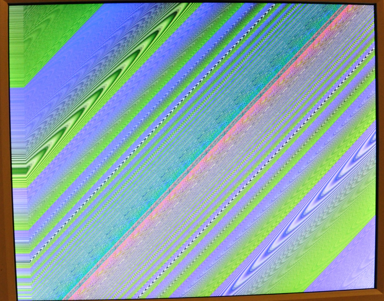
The frequency at which the scheme can work depends mainly on the scheme itself, but the type of FPGA, its “class of skrosti” plays a role. The meaning is approximately the same - in one clock cycle the signal must have time to run along the longest path of your circuit and switch the target register. When I exceeded the frequency for the solution being described, characteristic snot appeared on the screen.
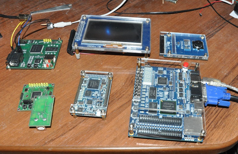
The project is prepared for four debugging boards, Terasic DE0, Terasic DE2-115, Terasic DE0-nano with LTM display instead of VGA, and also Mars Rover II. Terasic has excellent hardware, software is not so rosy. Documentation and samples are examples, but they are not always enough. For example, having already learned how to flash the FPGA directly, I killed the day by pushing the same firmware into the configuration memory (eeprom) (so that this firmware would load when the board was turned on). Another problem is that in Russia they are difficult to find at a reasonable price, and Taiwanese are not sent by regular mail. The Mars Rover II has a poorer functional, but it’s much better with descriptions and support; in the articles from their website I often found a solution to my next difficulties. My first debug motherboard was the first Mars Rover, it is weaker in terms of its capabilities, but also easier to master above mentioned ones, to try the very thing.
Since I used ALTERA-based debugging boards, QUARTUS, a free web edition, was used as the development environment. QUARTUS leaves an ambiguous impression. The main complaint is very unintuitive and poorly documented, no tutorials. At the same time, it performs its duties as an integrated development environment. This is a typical situation when working with FPGAs — it works, but the convenience (including ease of development) is at the last place, enthusiasts are not usually expected here.
So, we generate video on function. ibniz, or rather its “linear” subset will serve as a specification. The advantage is that, firstly, you can borrow a few ready-made demos, and secondly, you can compare the result of the work with the reference software implementation, which is very valuable, since debugging the scheme is much more complicated than debugging the program.
The work was mainly divided into two parts, the infrastructure that prepares the data and displays the result on the display and on the core that implements the individual elementary functions of ibniz.
The main component of the infrastructure is the VGA adapter. The usual approach is to use the frame buffer (s) that involves external memory in the project (there is little internal memory). This would complicate the project and make it impossible to use memory for anything else. Therefore, the core works synchronously with VGA, the color of the pixel is calculated and it is immediately drawn.
Disadvantages:
VGA frequency is imposed on the core
While the VGA fulfills the “invisible pieces of the screen,” the core is idle.
Hard real time, it is necessary to give another pixel for each clock, save there, then to spend it will not work.
The ibniz commands of direct writing to the frame buffer are not realizable, as well as transition operators.
Benefits:
Ease of implementation
You can use the width of the channel, which the memory would not have pulled.
Memory is stored for something else (sharing a resource would hardly be possible here).
Low latency, there is little confusion from it, but with the signal from the camera comes out beautifully, but this is another project.
Tru 60Hz video pleases the eye.
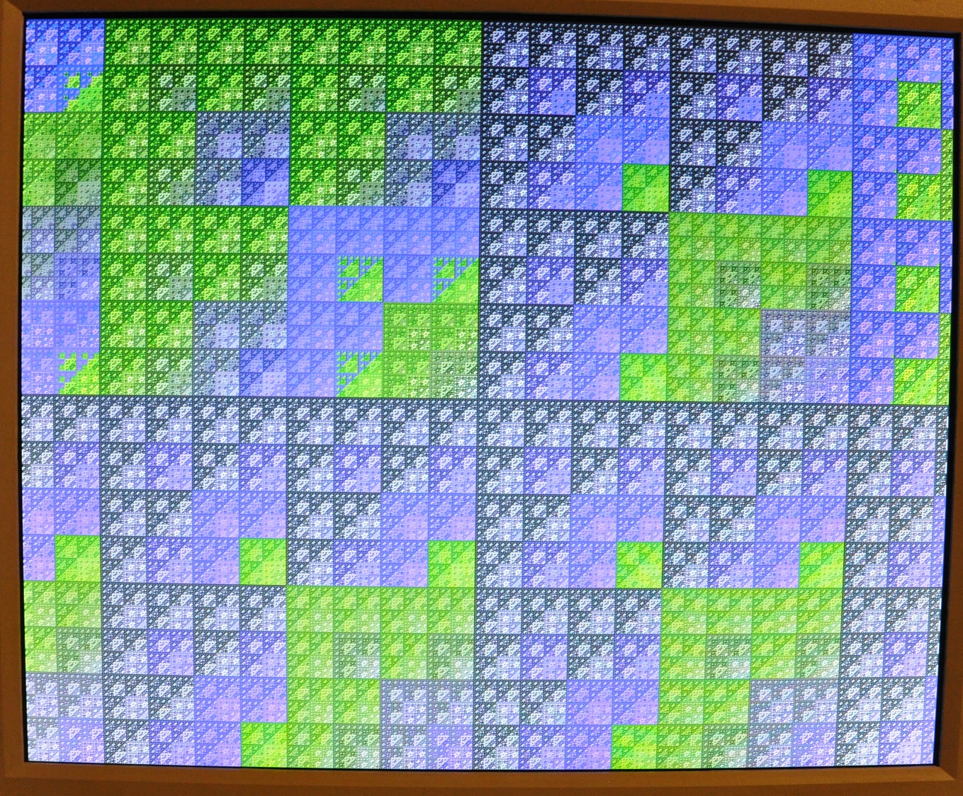
The core of the project consists of mathematical functions - sin, atan2, log, sqrt, as well as division; implemented them myself, using digit-to-digital algorithms ( CORDIC ), the benefit was the experience of software implementation. These are iterative algorithms, the number of iterations is proportional to the length of the arguments. My iteration is done per clock, that is, from receiving arguments at the input to output of the result, the number of ticks equal to the digit capacity of numbers passes, for ibniz it is 32. How to try it with the need to count a point per clock? With the help of conveying , the computing unit consists of 32 (hardware) stages. There is a delay, and for the sequence of blocks the delay accumulates. It is easy to fight with it, but I left it for clarity, as a result, the image is shifted to the right, and along the left edge you can see an artifact strip, the width of which corresponds to the total depth of the conveyor of a specific example.
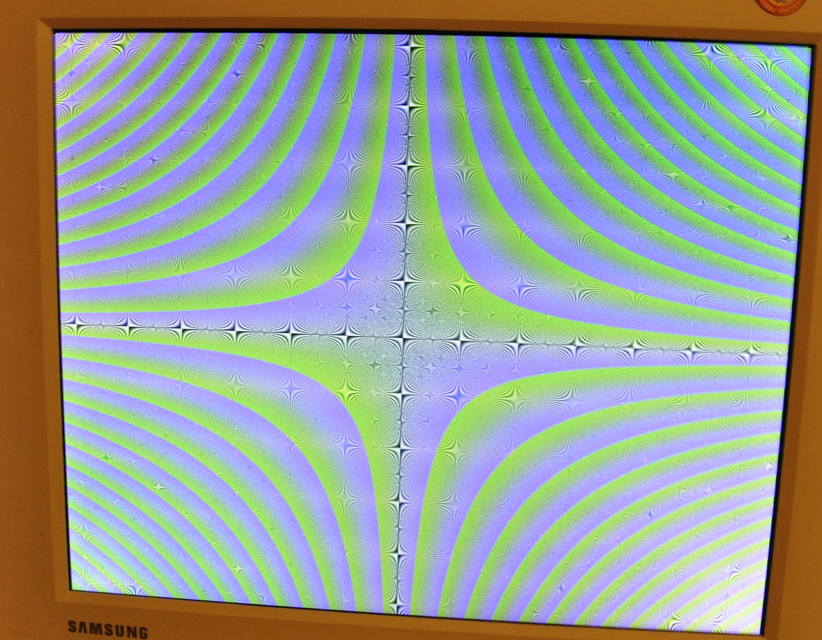
About generative art on Habré already wrote for example here , further my 5kop. When you start to generate computer pictures, at first you strive for the unusual, - paradoxical forms, bright inks to acidity. However, such “works” quickly get bored. An interesting thing is that in order to increase diversity, you have to impose restrictions. A “random” picture looks flat, but you can add a sense of volume by pulling it onto some form. In the Jupiter demo, an intermediate picture-texture is superimposed on the sphere. To do this, simply convert the coordinates from Cartesian to spherical as well, as described in this article . The sense of volume is enhanced by lighting, as well as movement, see a demo with four circles-spheres.
So, is it worth a programmer to climb into the circuitry? Only under the condition of serious intentions, it is necessary to at least know exactly the goal, since this is an energy-intensive matter, which is caused by working at a low level, by less sophisticated development tools and a less obvious logic of the program. On the other side of the scale - new opportunities and experiences. I am quite satisfied with my experience, besides the project described, I also made a procedural music generator , a MIDI synthesizer , a signal filter from a video camera.
Now I have a much more serious project at the stage of thinking over and writing a software model, a non-Neumann computer based on combinatorial logic . The main idea is that a dynamic tree of a functional program lives on a static large regular graph wired into iron, and the branches of the tree evolve whenever possible simultaneously. The nodes are as simple as possible, they can only use combinators; integers only in the form of Church numerals. The advantage should be the mass execution of simple symbolic operations in a pure functional style. Maybe something like a regular expression parsing or logical inference. Of course, in the overwhelming majority of practical problems, traditional architecture cannot be overtaken, but if suddenly there is at least one suitable area, you see, we will reach silicon. Well, or at least the architecture will appear with unlambda as an assembly language:
`` `s``s``sii`ki
`k. *` `s``s`ks
`` s`k`s`ks``s``s`ks``s`k`s`kr``s`k`sikk
`k``s`ksk
In this article I want to talk about my experience in studying development on FPGAs and to introduce my project - a video generator using a formula.
Purpose of the post
I am a C ++ programmer, professionally engaged in the development and maintenance of system software. About two years ago, I had a desire to diversify my experience by studying circuit design, more precisely programming an FPGA using the Verilog language. Next, I will tell you what came of it.
')
Objective
To direct the computational power of the FPGA to the needs of generative art: to generate real-time streaming video using a complex formula in high resolution, with a high frame rate. IBNIZ , a formula description language for generating a demo, developed by comrade viznut as a virtual platform for the demoscene, was chosen as a frontend. Previously, I implemented on the FPGA, on the platform " Mars Rover ", his other find .
Theory
Circuit design and programming
In my opinion, circuit design for a programmer is an interesting adjacent area for development. The description of the equipment, on the one hand, is in many ways similar to the writing of the program, which facilitates entry, and on the other hand, defines a completely different way to solve the applied problem, gives the engineer new possibilities and experience. Usually we write a program that runs sequentially, line by line. It is instructive to try to write a program, all parts of which work simultaneously.
So, this is interesting, but let's think about expediency. How to choose a task that will be justified on the FPGA? First, in some cases, the circuit design is more elegant and reliable software. For example, I programmed a sumo-bot on a microcontroller, made him a simple voice - a speaker hangs on one of the conclusions, the signal on it changes with a sound frequency. Everything is simple - a cycle, inside switching and delay. But the robot stopped for a while. To work at the same time, you need multitasking, you need to write a dispatcher, with increasing complexity turning into a real-time OS . In the decision on the FPGA, it is not necessary to divide the resource of the central calculator, the subsystem of the control of the speaker will remove some volume of the FPGAs and will not interfere with anyone further.
Secondly, a specialized circuit can have a lot more performance than a software solution. For a pixel-by-pixel processing of the 1280x1024 @ 60Hz video stream, it will be necessary to process 80 million in real time. there are not enough points per second, even on a powerful processor, the circuit design will give possibilities where it is richer (with certain limitations on the algorithm, the processing must be stereotypical, branching is undesirable).
Hdl
For programming FPGAs, you can use special languages such as Verilog and VHDL. In my opinion, they are much more convenient than the schematic editor, but people who are used to high-level programming are disappointed. My experience concerns (System) Verilog, but as far as I know, VHDL differs little. The scheme is described at the level of register transfers (RTL) , which seems to be natural, but the description is divided into two parts: the combinational circuit and synchronous logic. Here, for example, there is a cycle operator, I describe the division by a bar and I find that the combinational part cannot be described inside the loop body, only the synchronous one. There are macros, the macro language of the veralog is a S-shny preprocessor with the accuracy of replacing '#' with '' '. Well, the module can have numeric parameters (compile time), and that's probably all the means of generalized programming on our weapons.
RTL, synchronous circuits
In most cases, the developers of electronic circuits are limited to synchronous circuits. This means that there is a common clock signal (clock, clock), and the description is divided into a set of registers and combinational circuit, which determines how the register value on the next clock depends on the register value on the previous one. The combination scheme does not have its own state. Minus - some restriction of freedom, for example, I met a description of the implementation of a random number generator using an asynchronous scheme. In general, the architecture of the FPGA is designed to work only with synchronous circuits, and such fundamentally asynchronous modules like the PLL (PLL) are implemented as separate hardware blocks.
The PLL allows you to create several “clocks”, for example, to separate the computational module from the video adapter, so that each has its own frequency. As I understand it, asynchronous circuits refer to circuitry approximately as programmers to self-modifying code.
The frequency at which the scheme can work depends mainly on the scheme itself, but the type of FPGA, its “class of skrosti” plays a role. The meaning is approximately the same - in one clock cycle the signal must have time to run along the longest path of your circuit and switch the target register. When I exceeded the frequency for the solution being described, characteristic snot appeared on the screen.
Iron
The project is prepared for four debugging boards, Terasic DE0, Terasic DE2-115, Terasic DE0-nano with LTM display instead of VGA, and also Mars Rover II. Terasic has excellent hardware, software is not so rosy. Documentation and samples are examples, but they are not always enough. For example, having already learned how to flash the FPGA directly, I killed the day by pushing the same firmware into the configuration memory (eeprom) (so that this firmware would load when the board was turned on). Another problem is that in Russia they are difficult to find at a reasonable price, and Taiwanese are not sent by regular mail. The Mars Rover II has a poorer functional, but it’s much better with descriptions and support; in the articles from their website I often found a solution to my next difficulties. My first debug motherboard was the first Mars Rover, it is weaker in terms of its capabilities, but also easier to master above mentioned ones, to try the very thing.
Tools
Since I used ALTERA-based debugging boards, QUARTUS, a free web edition, was used as the development environment. QUARTUS leaves an ambiguous impression. The main complaint is very unintuitive and poorly documented, no tutorials. At the same time, it performs its duties as an integrated development environment. This is a typical situation when working with FPGAs — it works, but the convenience (including ease of development) is at the last place, enthusiasts are not usually expected here.
Implementation
So, we generate video on function. ibniz, or rather its “linear” subset will serve as a specification. The advantage is that, firstly, you can borrow a few ready-made demos, and secondly, you can compare the result of the work with the reference software implementation, which is very valuable, since debugging the scheme is much more complicated than debugging the program.
The work was mainly divided into two parts, the infrastructure that prepares the data and displays the result on the display and on the core that implements the individual elementary functions of ibniz.
The main component of the infrastructure is the VGA adapter. The usual approach is to use the frame buffer (s) that involves external memory in the project (there is little internal memory). This would complicate the project and make it impossible to use memory for anything else. Therefore, the core works synchronously with VGA, the color of the pixel is calculated and it is immediately drawn.
Disadvantages:
VGA frequency is imposed on the core
While the VGA fulfills the “invisible pieces of the screen,” the core is idle.
Hard real time, it is necessary to give another pixel for each clock, save there, then to spend it will not work.
The ibniz commands of direct writing to the frame buffer are not realizable, as well as transition operators.
Benefits:
Ease of implementation
You can use the width of the channel, which the memory would not have pulled.
Memory is stored for something else (sharing a resource would hardly be possible here).
Low latency, there is little confusion from it, but with the signal from the camera comes out beautifully, but this is another project.
Tru 60Hz video pleases the eye.
Core
The core of the project consists of mathematical functions - sin, atan2, log, sqrt, as well as division; implemented them myself, using digit-to-digital algorithms ( CORDIC ), the benefit was the experience of software implementation. These are iterative algorithms, the number of iterations is proportional to the length of the arguments. My iteration is done per clock, that is, from receiving arguments at the input to output of the result, the number of ticks equal to the digit capacity of numbers passes, for ibniz it is 32. How to try it with the need to count a point per clock? With the help of conveying , the computing unit consists of 32 (hardware) stages. There is a delay, and for the sequence of blocks the delay accumulates. It is easy to fight with it, but I left it for clarity, as a result, the image is shifted to the right, and along the left edge you can see an artifact strip, the width of which corresponds to the total depth of the conveyor of a specific example.
Beautiful
About generative art on Habré already wrote for example here , further my 5kop. When you start to generate computer pictures, at first you strive for the unusual, - paradoxical forms, bright inks to acidity. However, such “works” quickly get bored. An interesting thing is that in order to increase diversity, you have to impose restrictions. A “random” picture looks flat, but you can add a sense of volume by pulling it onto some form. In the Jupiter demo, an intermediate picture-texture is superimposed on the sphere. To do this, simply convert the coordinates from Cartesian to spherical as well, as described in this article . The sense of volume is enhanced by lighting, as well as movement, see a demo with four circles-spheres.
Total
So, is it worth a programmer to climb into the circuitry? Only under the condition of serious intentions, it is necessary to at least know exactly the goal, since this is an energy-intensive matter, which is caused by working at a low level, by less sophisticated development tools and a less obvious logic of the program. On the other side of the scale - new opportunities and experiences. I am quite satisfied with my experience, besides the project described, I also made a procedural music generator , a MIDI synthesizer , a signal filter from a video camera.
Now I have a much more serious project at the stage of thinking over and writing a software model, a non-Neumann computer based on combinatorial logic . The main idea is that a dynamic tree of a functional program lives on a static large regular graph wired into iron, and the branches of the tree evolve whenever possible simultaneously. The nodes are as simple as possible, they can only use combinators; integers only in the form of Church numerals. The advantage should be the mass execution of simple symbolic operations in a pure functional style. Maybe something like a regular expression parsing or logical inference. Of course, in the overwhelming majority of practical problems, traditional architecture cannot be overtaken, but if suddenly there is at least one suitable area, you see, we will reach silicon. Well, or at least the architecture will appear with unlambda as an assembly language:
`` `s``s``sii`ki
`k. *` `s``s`ks
`` s`k`s`ks``s``s`ks``s`k`s`kr``s`k`sikk
`k``s`ksk
Source: https://habr.com/ru/post/203018/
All Articles