DIY dimmer: a guide to the components
In the recent past, we shared with our dear readers a complete set of gerber files. So that everyone has the opportunity to order a printed circuit board. As inexpensive as we did.
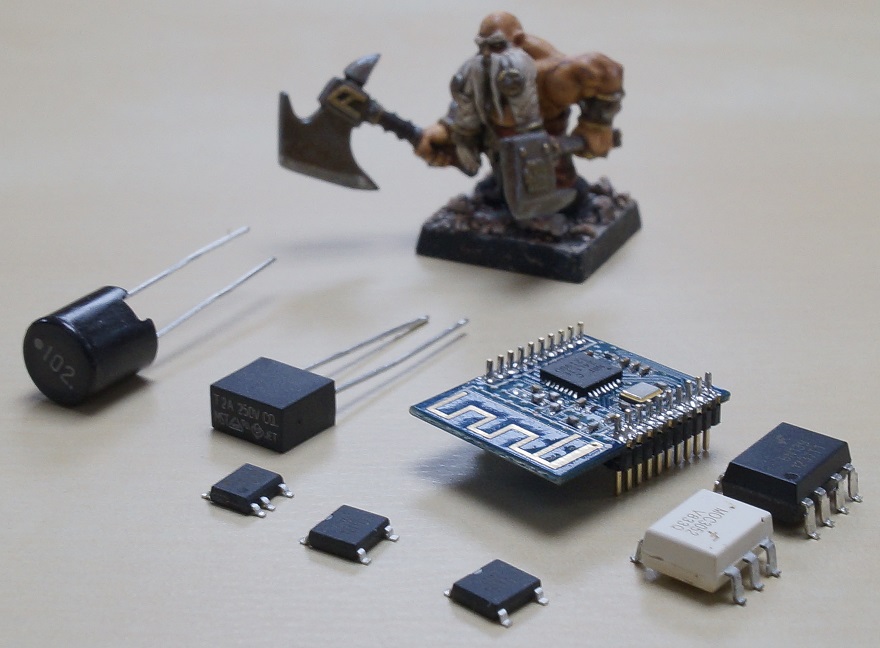
Today we take the next step. We publish the full specification of electronic components used in our DIY-dimmer. We have tried to make this specification become clear even to the most novice electronics. Under the cut is a large detailed table of components with photos (in perspective) of all the elements used.
')
A brief introduction to the course for those who first saw our project
We are developing a complete system of smart home. The “first sign” of our system is a DIY-dimmer. Here are its main characteristics:
If you want to join in the discussion of the features of the system, please read all our previous articles and comments to them. Most likely the questions after such an introduction will be much less.
- Work on the radio channel 2,4 GHz (its protocol, without licensing restrictions)
- Encrypted connection
- Installation without changing the standard wiring of an ordinary apartment
- Low power consumption
- The usual look of switches
- The possibility of independent expansion of both hardware and software functionality
- Open source code of both software and hardware
If you want to join in the discussion of the features of the system, please read all our previous articles and comments to them. Most likely the questions after such an introduction will be much less.
Want to keep abreast of all project events? It is not difficult at all!
You just need to subscribe to the update of our company in Habré and in the VKontakte group .
With VKontakte questions usually does not arise. To subscribe to Habr's updates, you need to go to the company’s page and click the “Subscribe” button in the block on the right.
With VKontakte questions usually does not arise. To subscribe to Habr's updates, you need to go to the company’s page and click the “Subscribe” button in the block on the right.
Schematic diagram of the device

Specification of components used
We will add photos as we receive the ordered components. Specifications of some elements are slightly different from the scheme. Possible ranges of passive components will be added to the table later. Updates will be announced in the comments.
| Designation | Name | Replacement options | Housing | A photo |
| U1 | PBS1.27 10pin x2 | Hatcher | ||
| 10-pin connector for radio module with lead pitch 1.27mm, 2 pcs. | ||||
| U2 | LNK304D | LNK305D, LNK306D | SO-8 | 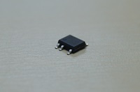 |
| Power converter | ||||
| U3 | MOC3052SM | SDIP6 | 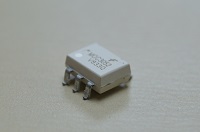 | |
| Optosimistor | ||||
| VO1 | 6N139S | SDIP8 | 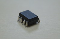 | |
| Optocoupler | ||||
| VD1, VD2 | TB10S | TDI |  | |
| Diode bridge | ||||
| T1 | T835-600G | T1635-600G | D2PAK | |
| Triac | ||||
| D1 | LED | 0805 | ||
| LED of your favorite color | ||||
| D2 | STTH1R06A | ES1J | SMA | |
| High-speed diode | ||||
| D3 | GS1J | S1j | SMA | |
| Rectifier diode | ||||
| C1 | 3,3uF x 450V | 2,2uF x 450V | Hatcher | |
| Electrolytic capacitor | ||||
| C2, C4, C5, C6 | 100n (0.1uF) | 0603 | ||
| SMD ceramic capacitor | ||||
| C3 | 10n (0.01uF) | 0603 | ||
| SMD ceramic capacitor | ||||
| C7 | 10uF x 10V | 10uF x 16V | Hatcher | |
| Electrolytic capacitor | ||||
| C8 | 100uF x 10V | Hatcher | ||
| Electrolytic condenser LOWESR | ||||
| R1, R2 | 470k 0.25W | Hatcher | ||
| Output resistor | ||||
| R3, R4 | 47R 1W | Hatcher | ||
| Flameproof Impedance Resistor (flameproof) | ||||
| R5, R6 | 10k 5% | 0603 | ||
| SMD resistor | ||||
| R7 | 200R 5% | 0603 | ||
| SMD resistor | ||||
| R8, R10 | 1.6k 1% | 0603 | ||
| SMD resistor | ||||
| R9 | 2k 1% | 0603 | ||
| SMD resistor | ||||
| R11 | 390R 1W | Hatcher | ||
| Output resistor | ||||
| R12 | 1k 5% | 0603 | ||
| SMD resistor | ||||
| L1 | 3,3uH | 1210 | ||
| SMD Throttle | ||||
| L2 | 1000uH | Hatcher | 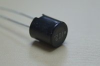 | |
| Power Output Throttle | ||||
| F1 | 250V 2A | Hatcher |  | |
| Fuse | ||||
| LINE | 2 pin connector | Hatcher | ||
| Power plug | ||||
Please note that in the product board, we tried to minimize the size of the enclosures of the elements and make maximum use of surface mounting. All chips used are in SMD packages. They look like this:
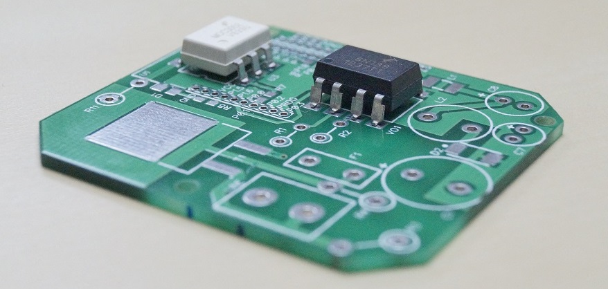
An attentive reader noticed on the title photo of the post an image of a new radio module. This is the module we use in the final layout of the DIY-dimmer. A separate article will be devoted to the issues of acquiring this module and compatible Chinese ready-made components.
Who can assemble himself?
Any brave pioneer in holding a soldering iron. Soldering iron should be with a very thin sting. It is better to use a soldering station. Settings scheme does not require.
Where to buy components?
Maximum savings can be obtained by ordering components from China through one of the intermediaries of the national auction TaoBao. Such a purchase has its own characteristics and some of the overheads, both in terms of lengthy terms and, if possible, in the end, but not of what I ordered. Plus, it should be borne in mind that ordering parts for 1-10 devices from China is most likely not at all profitable.
If you do not chase for maximum savings and want some level of comfort, all the necessary details in the foreseeable future will be available from us. In the form of sets of various complete sets. Possible complete sets dedicated survey at the end of this post. Do not pass by, vote, your opinion is important to us!
The estimated cost of a set of necessary parts (only parts, without a board and case) for a piece sale will be approximately 800 rubles. The price tag will be significantly reduced depending on the number of purchased sets.
The announcement of the following posts:
- The first photos of the first case of our DIY-dimmer + 3D-model for self-printing body on a 3D-printer.
- Module for connecting to a computer via USB: description, schematics, specification of components and a traditional set of gerber-files.
- Where to buy the right radio modules and what else can you buy in China for use in a home-made smart home?
- The first steps in programming NRF24LE1: blink LED
- Firmware NRF24LE1 with the help of available tools: Raspberry PI & TI MSP430 LaunchPad
Subscribe to our updates here and on VKontakte , participate in discussions, influence the course of the project.
PS Comment on the survey. The radio module itself is not included in all configurations; its price in China fluctuates around 300 rubles.
Source: https://habr.com/ru/post/202968/
All Articles