Modem 1200KN-01. Made in USSR
Based on the topic modem "Fiztekh-1200". Back in USSR , published on Habré 4 years ago, I decided to write a small reviewer of another Soviet modem with the unique name “Modem 1200KN Signal Conversion Device” .
Unfortunately, there is no free information about the principles of operation of this device. The electrical circuit diagram and pinout of the 1200KN-01 modem's connecting interfaces also remain a mystery to me. General technical information on the 1200KN series modem can be found in the Reference book “Technical means of the automated control system” edited by G. B. Kezing, but it is clearly not enough to put the modem into operation. In this regard, I did not manage to get the modem to work according to its intended purpose, however I could still get some information about this device.
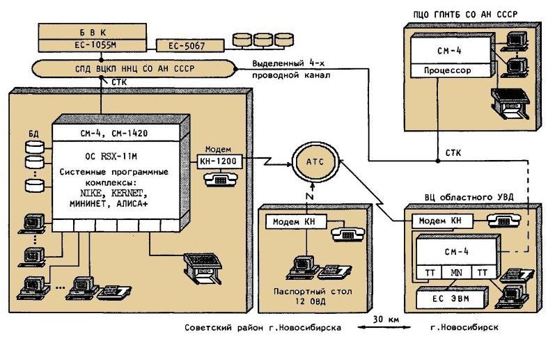
The modem was intended for data transmission in a synchronous or asynchronous manner via switched and dedicated communication lines with a speed of up to 1200 bps. This equipment was used, for example, in the framework of the “Central Air Traffic Control Center for ATC” project and was intended to unite heterogeneous computing equipment (EC computers, SM computers, etc.) into a single territorially distributed terminal network.
')
In the case of using a two-wire switched telephone line, the connection was established manually using a conventional telephone set connected to the 1200KN-01 modem.
Specifications modem 1200KN-01.
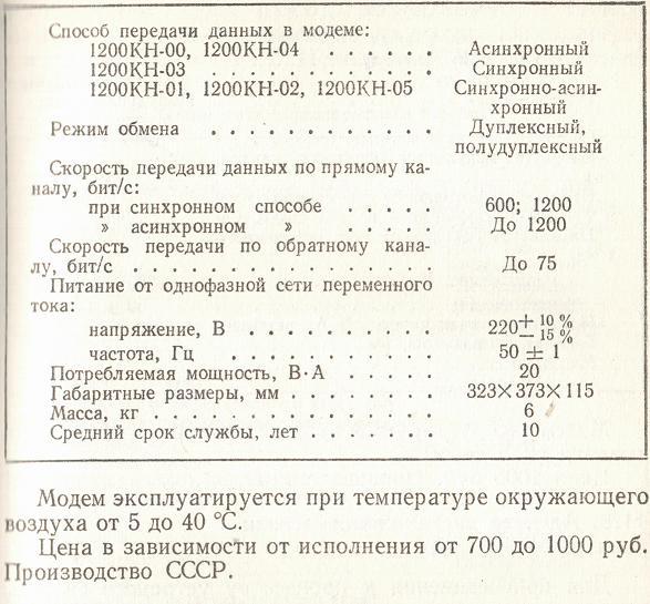
Information on the technical characteristics of the modem was found in the two-volume reference book “Technical means of the automated control system” edited by G. B. Kezling. Actually, all I know about the 1200KN-01 modem is placed in a small table:
Appearance.
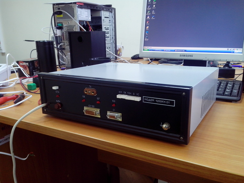
Modem 1200KN-01 is a complete device, made in a metal case.
All controls and displays, as well as connectors are located on the front panel of the modem.
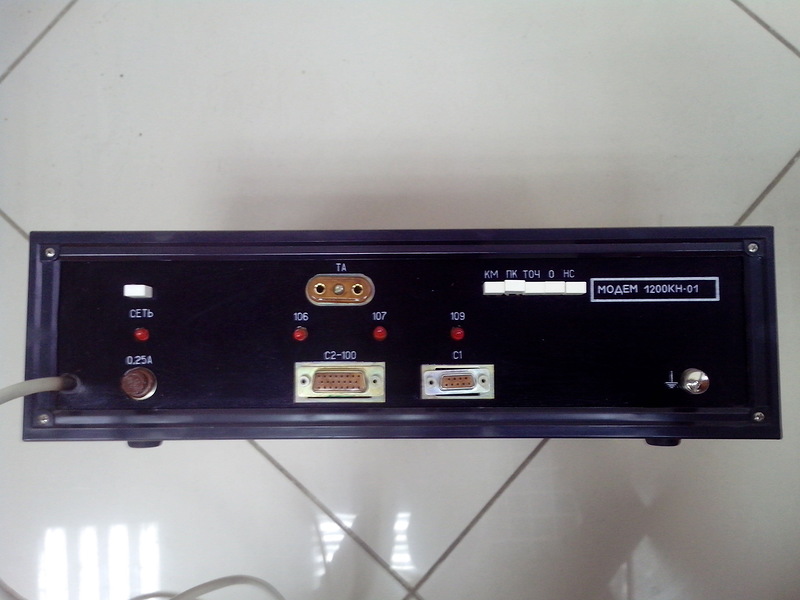
The connector JOINT S2-100 is designed to connect the 1200KN-01 modem with a computer. Two or four wire line is connected to the device using the connector C1. The two-wire telephone line is connected to pins 1 and 2 of connector C1.
The TA socket is intended for connecting a telephone set. LED indicators with markings 106, 107 and 109 are supposed to reflect the states of the signals of the CTS (Clear To Send), DSR (Data Set Ready) and CD (Carrier Detect) circuits, respectively.
The assignment of the five two-way switches is unknown. When you press the KM button, the telephone line is shorted.
One two Three. What's inside?
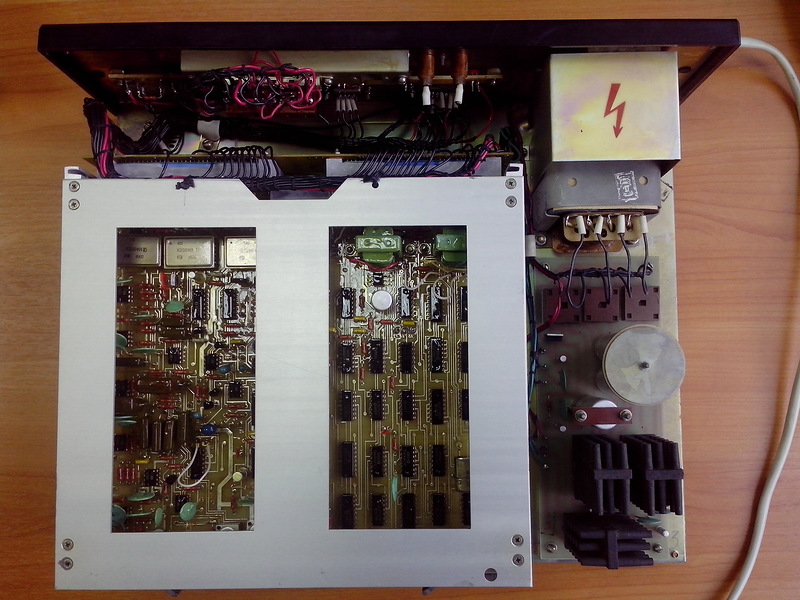
Removing the metal cover, you can see the inside of the device.
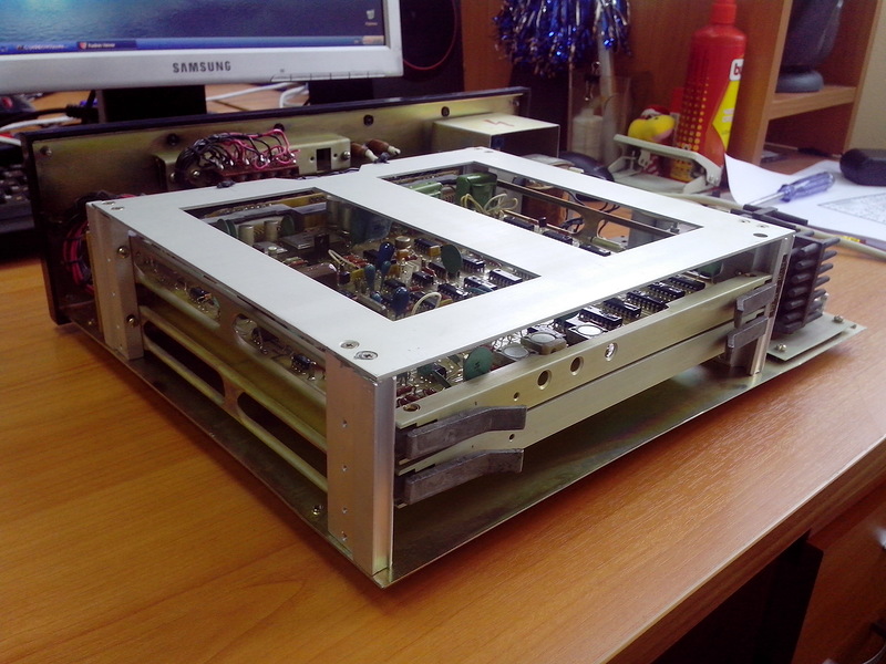
Almost all electronic components are concentrated on two motherboard modules installed on the chassis.
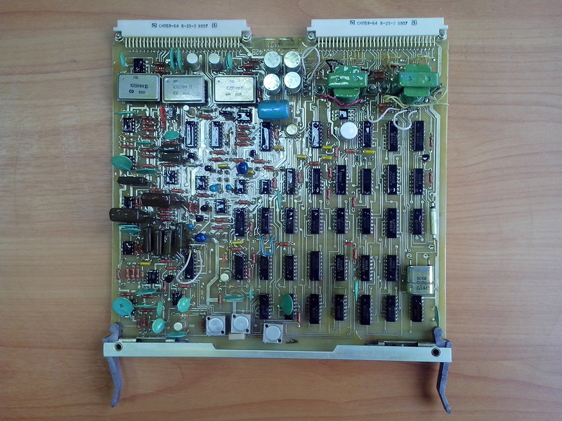
Module M-01.
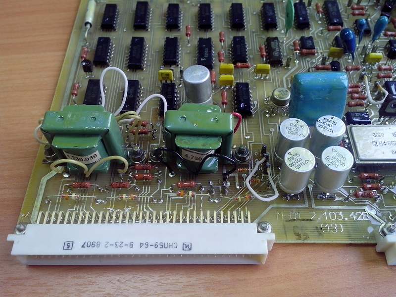
Module M-01. Components of the node matching modem with the line of communication.
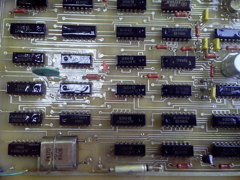
Module M-01. Almost all the chips of the K176 series with a nominal supply voltage of 9V ± 5%.
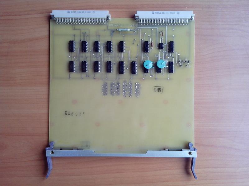
Module M-04. There are seats for three microcircuits, but they themselves are not soldered.
The End.
On this, in fact, everything.
If you have any information on the 1200KN-01 modem, circuit diagrams or instructions, let us know in the comments.
Unfortunately, there is no free information about the principles of operation of this device. The electrical circuit diagram and pinout of the 1200KN-01 modem's connecting interfaces also remain a mystery to me. General technical information on the 1200KN series modem can be found in the Reference book “Technical means of the automated control system” edited by G. B. Kezing, but it is clearly not enough to put the modem into operation. In this regard, I did not manage to get the modem to work according to its intended purpose, however I could still get some information about this device.
The modem was intended for data transmission in a synchronous or asynchronous manner via switched and dedicated communication lines with a speed of up to 1200 bps. This equipment was used, for example, in the framework of the “Central Air Traffic Control Center for ATC” project and was intended to unite heterogeneous computing equipment (EC computers, SM computers, etc.) into a single territorially distributed terminal network.
')
In the case of using a two-wire switched telephone line, the connection was established manually using a conventional telephone set connected to the 1200KN-01 modem.
Specifications modem 1200KN-01.
Information on the technical characteristics of the modem was found in the two-volume reference book “Technical means of the automated control system” edited by G. B. Kezling. Actually, all I know about the 1200KN-01 modem is placed in a small table:
Appearance.
Modem 1200KN-01 is a complete device, made in a metal case.
All controls and displays, as well as connectors are located on the front panel of the modem.
The connector JOINT S2-100 is designed to connect the 1200KN-01 modem with a computer. Two or four wire line is connected to the device using the connector C1. The two-wire telephone line is connected to pins 1 and 2 of connector C1.
The TA socket is intended for connecting a telephone set. LED indicators with markings 106, 107 and 109 are supposed to reflect the states of the signals of the CTS (Clear To Send), DSR (Data Set Ready) and CD (Carrier Detect) circuits, respectively.
The assignment of the five two-way switches is unknown. When you press the KM button, the telephone line is shorted.
One two Three. What's inside?
Removing the metal cover, you can see the inside of the device.
Almost all electronic components are concentrated on two motherboard modules installed on the chassis.
Module M-01.
Module M-01. Components of the node matching modem with the line of communication.
Module M-01. Almost all the chips of the K176 series with a nominal supply voltage of 9V ± 5%.
Module M-04. There are seats for three microcircuits, but they themselves are not soldered.
The End.
On this, in fact, everything.
If you have any information on the 1200KN-01 modem, circuit diagrams or instructions, let us know in the comments.
Source: https://habr.com/ru/post/202508/
All Articles