Video surveillance in the countryside via 3G Internet
There was such a task: Install video surveillance, 15 km from the city, where only gprs internet is available.
Conditions:
To solve this problem, I decided to build such a network.
Get the cheapest VDS server. Inexpensive TP-LINK MR 3420 router, 3G modem from beeline, ip camera. And build such a network as in the diagram.
The essence of the idea is as follows: On the server, an openvpn server rises, an openvpn client rises on the router, then we merge the local network with the openvpn network. Then we forward the necessary ports on the server.
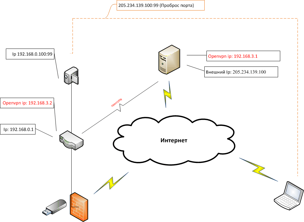
Network Description:
The first network is a router + ip camera + your computer (gateway). The network address will be 192.168.0.0
At the router 192.168.0.1
At the camera 192.168.0.100
Your computer, which will be the gateway 192.168.0.2
')
The second network is the openVPN network - 192.168.3.0
The openVPN IP address of your router will be 192.168.3.2
Your server’s IP address will be 192.168.3.1
And the external ip address of the server for the example will be 205.234.139.100
What do we need.
Working process.
How to set up an openvpn server, up to the point “Networking”, is described here: Configuring the OpenVPN server for client connections
The server configuration looks like this:
To give each client a specific ip address, there is a line in the config
Create a document on the server in the / etc / openvpn / folder
Called ipp.txt
And in it we write “client name, ip address”
For example like this
How to flash a router is described by reference: TP-Link TL-MR3420 & TL-MR3220
First you need to give access to the router on the Internet to install additional software.
In order that the router could go online we go through the web (http://192.168.1.1), go to the network. Next, click edit in lan
Go to the General Setup tab and change the ip local network to
IP Address: 192.168.0.1
Mask: 255.255.255.0
Gateway: 192.168.0.2
DNS: 8.8.8.8

In order for the changes to take effect, click "Save & Apply"
On the computer we will install ip 192.168.0.2, and use it as a gateway.
Now you need to expand the memory of the router to install additional software.
To do this, take the flash drive (for example, 4 GB) and format it with the ext4 file system.
Then we insert it into the USB hub and connect it to the USB hub router.
Then you need to transfer all the settings to the flash drive and make it mount itself at the start.
Install packages for flash drives:
Create a connection point:
Then we mount the flash drive:
Copy the installed packages there:
Config a little rule:
To look like this:
Then reboot the router:
Now we are not limited to the original size of the flash router. And we can afford to put almost everything
We look at an empty seat:
Now we need to install the openvpn client on the router, along with the text editor nano, the file manager mc, and the luci crack.
Install the packages we need:
For mc to work properly, you need to complete two lines:
And so that each time they are not done by hand, you need to add them to / etc / profile:
Then we copy the keys and certificates created on the openvpn server to the router in / etc / openvpn /:
Rule the config:
Run openvpn:
If your Internet connection is OK and the openvpn configuration file is correct, you should see this:
If you want the vpn connection to be reestablished after each router reload, add this line to /etc/rc.local before the exit 0 line:
Let's unite the networks 192.168.0.0 and 192.168.3.0:
Your ip of the openvpn server is 192.168.3.1, and your ip on the openvpn router of the tap0 adapter 192.168.3.2
Then, in order for your server to see your local network (192.168.0.0), you need to set a route on the server.
Now your local network on the router is visible to the server with openvpn.
Suppose your ip camera is working on port 99, then in order to forward the port of the camera or other network device, write these lines in the console, or as described below, create a file and write to it:
Now you can connect to the ip camera at 205.234.139.100:99.
And in order not to do it manually after rebooting the server, create a script in the / root / folder with a file named start
and give him the right to perform:
Then add the line to / etc / crontab
Now, after restarting the server, the script will automatically start.
We insert the modem into a USB hub,
And we write the dmesg command, you should see something like this:
This suggests that the modem is installed and defined as eth2.
Next we need to add 2 network interfaces.
1. 3G
2. VPN
for this rule config:
3G we will have a DHCP client, and a VPN unmanaged adapter, we add:
In general, the config should look something like this:
So that the server can see all 3 networks, you need to combine them in the firewall
To do this, change the file / etc / config / firewall
Do something like this:
And we reboot the router
In order to increase the 3G modem signal, you need to assemble a Kharchenko antenna.
Usually, popular 3G modems operate at frequencies from 800 to 2100 MHz.
This is done simply.
We will need:
Let's start.

The next step is to solder the other end of the wire to the modem:
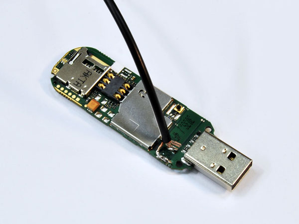
We open the modem case.
On the front side there are: a module for a memory card, contacts for a SIM card, a radio module under the cover, a connector, an internal antenna and a USB output.
Interestingly, this connector is not available without disassembling the case, that is, almost all the owners of this modem do not even suspect about this connector. Let it remain in place, we do not need it and do not interfere at all. And the internal antenna bothers us:
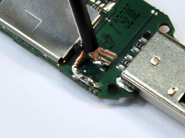
The antenna is etched right on the board, and we need to turn it off. To do this, first bite the SMD capacitor, designed for resonant matching of the antenna. Then with a small mill, clamped into a drill, we make a cut through the antenna, leaving only a small platform for soldering the cable. The cut is done shallowly, as the PCB is multi-layered. We call the tester, whether the “amputation” was successful and whether there is no short-circuit between the cable soldering area and the cut off antenna. By the way, sometimes this site can have a short circuit to the ground - these are the architectural features of some modems. If we did not cut off the internal antenna, then after connecting the external antenna, the signal would be divided between them, a mismatch would occur and nothing would have happened.
Solder the cable to the modem. We solder quickly, accurately and accurately, do not overheat the board. We solder the central core to the site left over from the internal antenna; braid solder to any place that is the ground and located as close as possible to the site with a soldered central residential.
After soldering the cable, you need to carefully assemble the modem and you need to raise the antenna to the maximum height, then use the sample method to catch the best signal and fix it in place.
That's all.
Conditions:
- Cameras can be controlled via the Internet
- Limited budget
- The city has 3G internet but not in the area.
- Cellular operators do not give "White and static ip address."
- There is no other Internet.
To solve this problem, I decided to build such a network.
Get the cheapest VDS server. Inexpensive TP-LINK MR 3420 router, 3G modem from beeline, ip camera. And build such a network as in the diagram.
The essence of the idea is as follows: On the server, an openvpn server rises, an openvpn client rises on the router, then we merge the local network with the openvpn network. Then we forward the necessary ports on the server.
Network Description:
The first network is a router + ip camera + your computer (gateway). The network address will be 192.168.0.0
At the router 192.168.0.1
At the camera 192.168.0.100
Your computer, which will be the gateway 192.168.0.2
')
The second network is the openVPN network - 192.168.3.0
The openVPN IP address of your router will be 192.168.3.2
Your server’s IP address will be 192.168.3.1
And the external ip address of the server for the example will be 205.234.139.100
What do we need.
- Computer.
- Temporary Internet access via computer.
- A router that supports OpenWRT and a 3G usb modem. (for example TP-LINK MR 3420)
- Server with external ip address based on Linux.
- 3G usb modem (I used Huawey).
- IP video camera.
- A good USB hub, with external power (For expanding USB ports for 3G modem and flash drives).
Working process.
- We configure on the openVPN server, we generate keys for the client of openVPN.
- We configure on openWRT + openVPN router and 3G modem for Internet access.
- If the 3G connection catches badly, collect the Kharchenko antenna to amplify the signal.
Configure openVPN on the server.
How to set up an openvpn server, up to the point “Networking”, is described here: Configuring the OpenVPN server for client connections
The server configuration looks like this:
daemon local 205.234.139.100 # ip port 1194 mode server proto tcp crl-verify crl.pem dev tap ca ca.crt cert server.crt key server.key dh dh1024.pem client-config-dir ccd server 192.168.3.0 255.255.255.0 # ip openvpn push "route 192.168.3.0 255.255.255.0" ifconfig-pool-persist ipp.txt keepalive 10 120 comp-lzo persist-key persist-tun client-to-client status openvpn-status.log log /var/log/openvpn.log verb 3 To give each client a specific ip address, there is a line in the config
ifconfig-pool-persist ipp.txt Create a document on the server in the / etc / openvpn / folder
Called ipp.txt
nano /etc/openvpn/ipp.txt And in it we write “client name, ip address”
For example like this
openwrt,192.168.3.2 Firmware and configuration of the router TP-LINK MR3420.
How to flash a router is described by reference: TP-Link TL-MR3420 & TL-MR3220
First you need to give access to the router on the Internet to install additional software.
In order that the router could go online we go through the web (http://192.168.1.1), go to the network. Next, click edit in lan
Go to the General Setup tab and change the ip local network to
IP Address: 192.168.0.1
Mask: 255.255.255.0
Gateway: 192.168.0.2
DNS: 8.8.8.8
In order for the changes to take effect, click "Save & Apply"
On the computer we will install ip 192.168.0.2, and use it as a gateway.
Now you need to expand the memory of the router to install additional software.
To do this, take the flash drive (for example, 4 GB) and format it with the ext4 file system.
Then we insert it into the USB hub and connect it to the USB hub router.
Then you need to transfer all the settings to the flash drive and make it mount itself at the start.
Install packages for flash drives:
opkg update opkg install kmod-usb-uhci kmod-usb-storage block-mount kmod-fs-ext4 insmod usb-ohci Create a connection point:
mkdir /mnt/sda Then we mount the flash drive:
mount -t ext4 /dev/sda /mnt/sda -o rw,sync Copy the installed packages there:
tar -C /overlay -cvf - . | tar -C /mnt/sda -xvf – Config a little rule:
vi /etc/config/fstab To look like this:
config 'mount' option target /overlay option device /dev/sda option fstype ext4 option options rw,sync option enabled 1 option enabled_fsck 1 Then reboot the router:
reboot Now we are not limited to the original size of the flash router. And we can afford to put almost everything
We look at an empty seat:
df –h Filesystem Size Used Available Use% Mounted on rootfs 3.7G 128.2M 3.4G 4% / /dev/root 2.0M 2.0M 0 100% /rom tmpfs 14.3M 688.0K 13.6M 5% /tmp tmpfs 512.0K 0 512.0K 0% /dev /dev/sda 3.7G 128.2M 3.4G 4% /overlay overlayfs:/overlay 3.7G 128.2M 3.4G 4% / Now we need to install the openvpn client on the router, along with the text editor nano, the file manager mc, and the luci crack.
Install the packages we need:
opkg install openvpn nano mc luci-i18n-russian For mc to work properly, you need to complete two lines:
export TERMINFO=/usr/share/terminfo export TERM=xterm And so that each time they are not done by hand, you need to add them to / etc / profile:
nano /etc/profile Then we copy the keys and certificates created on the openvpn server to the router in / etc / openvpn /:
ca.crt dh1024.pem openwrt.crt openwrt.key ta.key Rule the config:
nano /etc/config/openvpn client tls-client dev tap proto tcp remote 205.234.139.100 1194 # Ip resolv-retry infinite nobind persist-tun persist-key ca /etc/openvpn/ca.crt cert /etc/openvpn/openwrt.crt key /etc/openvpn/ openwrt.key dh /etc/openvpn/dh1024.pem comp-lzo verb 3 Run openvpn:
openvpn --config /etc/config/openvpn If your Internet connection is OK and the openvpn configuration file is correct, you should see this:
- Initialization Sequence Completed
If you want the vpn connection to be reestablished after each router reload, add this line to /etc/rc.local before the exit 0 line:
openvpn --config /etc/config/openvpn & exit 0 Let's unite the networks 192.168.0.0 and 192.168.3.0:
Your ip of the openvpn server is 192.168.3.1, and your ip on the openvpn router of the tap0 adapter 192.168.3.2
Then, in order for your server to see your local network (192.168.0.0), you need to set a route on the server.
ip route add 192.168.0.0/24 via 192.168.3.2 Now your local network on the router is visible to the server with openvpn.
Set up port forwarding:
Suppose your ip camera is working on port 99, then in order to forward the port of the camera or other network device, write these lines in the console, or as described below, create a file and write to it:
EXT_IP="205.234.139.100" # ip INT_IP="192.168.3.1" # (ip tap0) EXT_IF=venet0:0 # ip INT_IF=tap0 # openvrt LAN_IP="192.168.0.100" # ip SRV_PORT=99 # iptables -t nat -A PREROUTING --dst $EXT_IP -p tcp --dport $SRV_PORT -j DNAT --to-destination $LAN_IP iptables -t nat -A POSTROUTING --dst $LAN_IP -p tcp --dport $SRV_PORT -j SNAT --to-source $INT_IP iptables -t nat -A OUTPUT --dst $EXT_IP -p tcp --dport $SRV_PORT -j DNAT --to-destination $LAN_IP iptables -I FORWARD 1 -i $EXT_IF -o $INT_IF -d $LAN_IP -p tcp -m tcp --dport $SRV_PORT -j ACCEPT Now you can connect to the ip camera at 205.234.139.100:99.
And in order not to do it manually after rebooting the server, create a script in the / root / folder with a file named start
and give him the right to perform:
chmod 777 /root/start Then add the line to / etc / crontab
@reboot root /root/start Now, after restarting the server, the script will automatically start.
Install usb 3g Ethernet modem from huawey
opkg update opkg install usb-modeswitch usb-modeswitch-data kmod-usb-net-cdc-ether We insert the modem into a USB hub,
And we write the dmesg command, you should see something like this:
[ 99.220000] usb 1-1.1.1: new high-speed USB device number 6 using ehci-platform [ 99.330000] cdc_ether 1-1.1.1:1.0: eth2: register 'cdc_ether' at usb-ehci-platform-1.1.1, CDC Ethernet Device, 58:2c:80:13:92:63 This suggests that the modem is installed and defined as eth2.
Next we need to add 2 network interfaces.
1. 3G
2. VPN
for this rule config:
nano /etc/config/network 3G we will have a DHCP client, and a VPN unmanaged adapter, we add:
config interface '3G' option ifname 'eth2' option _orig_ifname 'eth2' option _orig_bridge 'false' option proto 'dhcp' config interface 'VPN' option ifname 'tap0' option _orig_ifname 'tap0' option _orig_bridge 'false' option proto 'none' In general, the config should look something like this:
config interface 'loopback' option ifname 'lo' option proto 'static' option ipaddr '127.0.0.1' option netmask '255.0.0.0' config interface 'lan' option _orig_ifname 'eth0 wlan0' option _orig_bridge 'true' option proto 'static' option netmask '255.255.255.0' option type 'bridge' option ipaddr '192.168.0.1' option ifname 'eth0' option send_rs '0' config interface '3G' option ifname 'eth2' option _orig_ifname 'eth2' option _orig_bridge 'false' option proto 'dhcp' config switch option name 'eth0' option reset '1' option enable_vlan '1' config switch_vlan option device 'eth0' option vlan '1' option ports '0 1 2 3 4' config interface 'VPN' option ifname 'tap0' option _orig_ifname 'tap0' option _orig_bridge 'false' option proto 'none' So that the server can see all 3 networks, you need to combine them in the firewall
To do this, change the file / etc / config / firewall
nano /etc/config/firewall nano /etc/config/firewall Do something like this:
config defaults option syn_flood '1' option input 'ACCEPT' option output 'ACCEPT' option forward 'ACCEPT' config include option path '/etc/firewall.user' config zone option name 'newzone' option input 'ACCEPT' option forward 'ACCEPT' option output 'ACCEPT' option masq '1' option network '3G lan vpn' And we reboot the router
reboot Gain 3G signal on the modem.
In order to increase the 3G modem signal, you need to assemble a Kharchenko antenna.
Usually, popular 3G modems operate at frequencies from 800 to 2100 MHz.
This is done simply.
We will need:
- RG6U wire (thick white for antennas - the least attenuation on it) 6 meters
- Connector on it
- A piece of copper wire from 1 to 4 mm thick (I have 1.5)
- Shaving foam cap.
- Soldering iron, solder, rosin and some skills to work with them.
- A piece of plywood (120mm by 134mm) and foil. Or not etched board, covered with copper on one side.
Let's start.
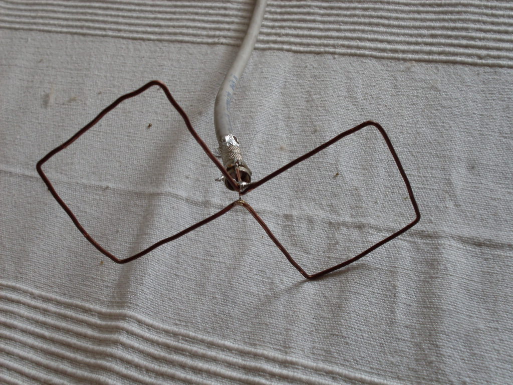
- We take a piece of our wire and bend it into two squares, as shown in the figure. Side of the square should be 53mm
- The ends of the two squares are soldered together to form a solid construction, and we apply solder to the opposite corner as well.
- We clean the antenna wire and put the connector on it, make the core of the wire so that it looks out of the connector for a centimeter
- We solder a piece of the core of the wire to the side of the connector body (since it is not always possible to solder the wire sheath with rosin)
- After that we solder both pins coming from the connector to our squares.
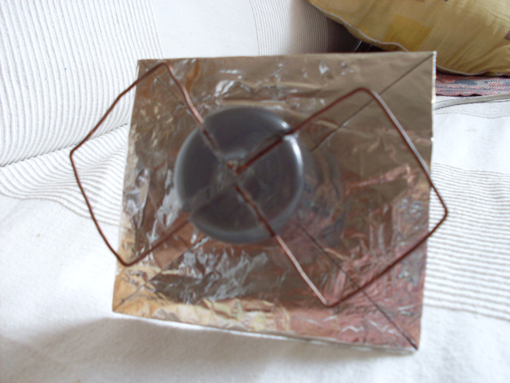
- Now we make a reflector for better reception - we take our plywood 120 by 135 mm and wrap it in foil, we make a hole for the wire in the middle.
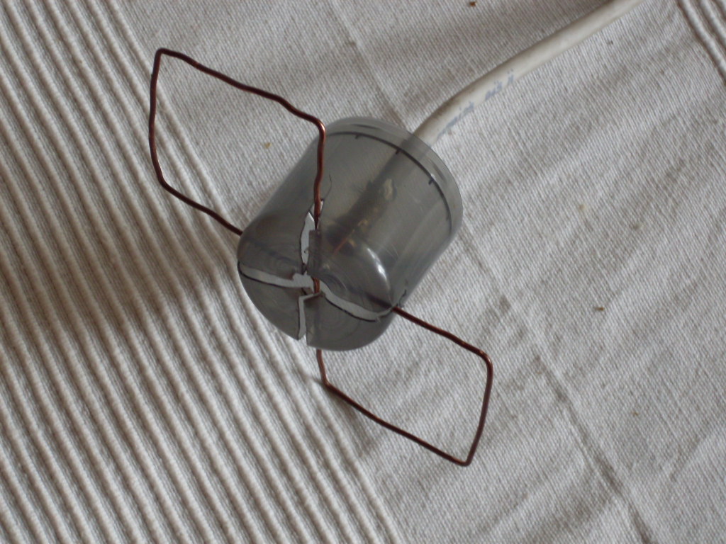
- The wire frame of the antenna should be above the reflector at a distance of 35mm, for this we take a cap from the foam to shave or something similar. It is 4.5 cm in height, so we cut 1 cm slots in it so that the antenna is at the right distance from the reflector.
- Behind all this construction we substitute a reflector made by us earlier and we get a ready-made antenna:
The next step is to solder the other end of the wire to the modem:
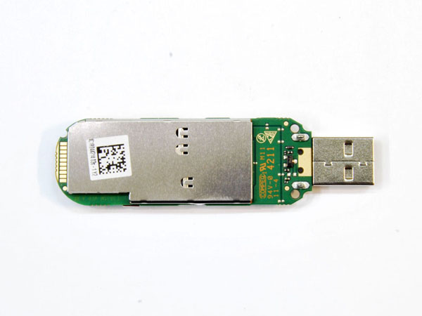
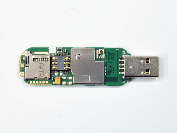
We open the modem case.
On the front side there are: a module for a memory card, contacts for a SIM card, a radio module under the cover, a connector, an internal antenna and a USB output.
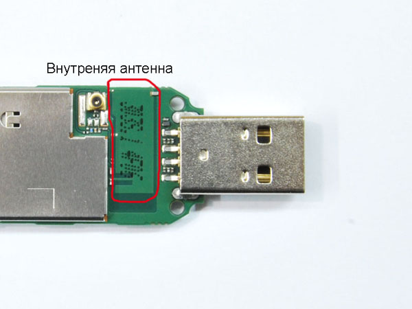
Interestingly, this connector is not available without disassembling the case, that is, almost all the owners of this modem do not even suspect about this connector. Let it remain in place, we do not need it and do not interfere at all. And the internal antenna bothers us:
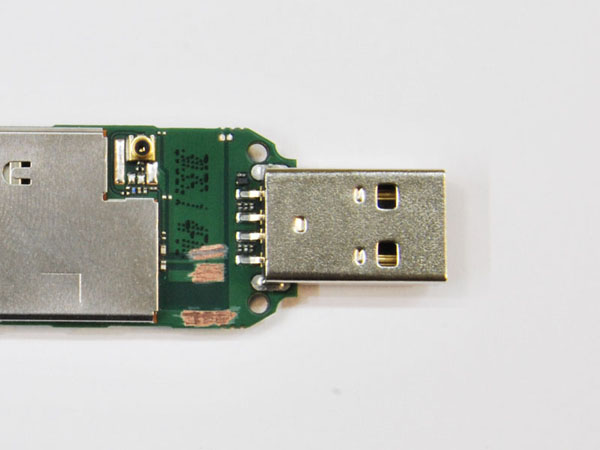
The antenna is etched right on the board, and we need to turn it off. To do this, first bite the SMD capacitor, designed for resonant matching of the antenna. Then with a small mill, clamped into a drill, we make a cut through the antenna, leaving only a small platform for soldering the cable. The cut is done shallowly, as the PCB is multi-layered. We call the tester, whether the “amputation” was successful and whether there is no short-circuit between the cable soldering area and the cut off antenna. By the way, sometimes this site can have a short circuit to the ground - these are the architectural features of some modems. If we did not cut off the internal antenna, then after connecting the external antenna, the signal would be divided between them, a mismatch would occur and nothing would have happened.
Solder the cable to the modem. We solder quickly, accurately and accurately, do not overheat the board. We solder the central core to the site left over from the internal antenna; braid solder to any place that is the ground and located as close as possible to the site with a soldered central residential.
After soldering the cable, you need to carefully assemble the modem and you need to raise the antenna to the maximum height, then use the sample method to catch the best signal and fix it in place.
That's all.
Sources:
Source: https://habr.com/ru/post/202278/
All Articles