Realization of a dream, or Radio 86RK - 25 years later
In the already distant 1986, I had a dream. Rather, DREAM - build your own micro-computer "Radio-86RK", the scheme of which was published in the magazine "Radio" (and which has already been mentioned many times on Habré, for example, here - habrahabr.ru/post/172405 ).
Before that, I had already figured out a bit with microprocessor technology in a series of publications several years earlier in the same Radio about the construction of the Radio Micro 80 microcomputer. Unfortunately, the circuit design of the Micro 80 was extremely difficult (more than 200 microcircuits), so it was practically impossible for me to repeat it both because of the complexity of the construction and because it was impossible to get the details.
So for the time being, I could only write programs on machine codes in a notebook in a box and dream of a wizard in a helicopter of any color that suddenly gives me this very Micro 80.
The situation has to some extent changed after the publication of articles on Radio 86RK. 86RK was much simpler - it contained “only” 29 microcircuits. Only if before that I clearly understood that there was no chance at all, then there seemed to be an opportunity to get my own micro-computer theoretically, but in practice the issue with the details was almost unresolvable anyway.
')
I will explain a little - at that time everything was in short supply, and radio components were no exception to this rule. Moreover, many of the details, in principle, did not come in retail sales. Nevertheless, it was possible to get everything. In large cities, there were places (often near stores such as Young Technician, etc.) where it was worthwhile to stand with an absent minute or two, how did the “comrades” who were spinning nearby approach you and casually asked - “Is there anything you need? ". Naturally, such activity was completely illegal, and was regularly suppressed by the relevant law enforcement agencies. Also, as in any criminal business, there has always been a danger that you will purposefully be “thrown”, “scouted out” or “substituted” in general. Accordingly, to me, as a resident of a small village, this option was not very suitable - and logistically it was extremely complicated, and it was just scary. There were simply no other options (in the absence of relatives / acquaintances working in enterprises where there could be a nomenclature of parts required).
Therefore, my mood has only deteriorated - it is better to clearly know that it is impossible to do this than to constantly suffer, wondering if it is impossible to somehow dodge and find the necessary components. In such torments, a couple of years passed, I went to study at a university in one of the largest cities of the Union, and the ghost of 86 RC became more distinct. Having cooperated with a friend, we made a foray into the firm shop “Electronics”, easily attracted the attention of the “merchants” who were there and became owners of almost the complete set of everything necessary for assembling RK - from microchips to the board and keyboard buttons.
Then everything went somehow wrong. Now it is even difficult for me to understand / remember why we failed. The fact remains that the computer did not work.
I had many childhood dreams / desires of completely different scales and importance, and most of them came true. However, a couple of months ago, I suddenly realized that there seems to be one more unfulfilled, but firmly entrenched dream somewhere in the depths of consciousness - after all, to build Radio 86RK. And not to buy, but to build it yourself, and as close as possible to what I could have done more than 20 years ago.
By now, for almost 20 years, I have not taken a soldering iron and an oscilloscope in my hands, so that some of the skills that were available were undermined and forgotten. Nothing - I decided that it would even be more interesting.
First, it was necessary to decide on some basic things. First, the specific scheme of the device. It is clear that there is a very original scheme, published in Radio in 1986, but even to it later corrections / additions were repeatedly published. In addition, operative memory was one of the weakest points of the 86RK. In the base case, its volume was 16K (namely, sixteen KILobytes), and it was organized on 8 microcircuits 565RU3. Even the new RU3s did not work very reliably, and how the products of more than 20 years ago will work (the new ones, naturally, haven’t been released a long time ago) could surely be assumed. On the other hand, I really didn’t want to move away from the original - after all, it was possible to simply assemble an emulator on a FPGA or even AVR. Therefore, on the Internet, a scheme was found using modern SRAM memory. In addition to reducing the number of cases of the memory itself (instead of 16 RUUs for the 32K version, only one is needed), a pair of microcircuits were also thrown out, ensuring the operation of the old memory. However, everything else (including the memory address space) absolutely corresponded to the original, i.e. any programs for the original 86RK will be able to work on this version, even if they access hardware resources directly.
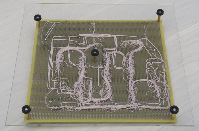
The second big decision was related to the choice of which board to do all this on. For the scheme found, there was also a very nice printed circuit board, which, moreover, could be bought. However, it seemed to me that it would be somehow dishonest - too simple. After all, it was possible to buy an assembled computer in the same place ... Therefore, it was decided to go, probably the most difficult way - a mock-up board with installation of MGTF wire.
Next you had to choose the power supply circuit. The options were from using the most original scheme (a pretty confused implementation of a classic power supply) to using a standard ATX format power supply. 86 (or rather, the microprocessor 58080) requires 3 supply voltages (+5, -5 and +12 V) and many power supplies from conventional PC-shki provide this. In the end, I decided to use a standard power module installed on the board. Something from 9 to 36 V is fed to the input of this type, we get three necessary voltages at the output, and even with the desired on / off sequence.
The last question I spent some time thinking about is what to do with the keyboard. So it was tempting to make a PCB, trying LUT (laser-iron technology) for the original keyboard, but, ultimately, it became interesting to understand a little about modern technologies too, so I decided to leave the PS / 2 keyboard adapter built on the ATMega 48 microcontroller. In fact, this adapter connects to the 86 and simulates the original 86 matrix keyboard, while on the other hand this adapter has the most common modern PC keyboard with PS / 2 interface (USB is much more difficult to implement). It is curious that the computing power of this microcontroller is noticeably higher than that of the entire 86RK computer ...
Finally, it's time to start buying different crap, figovin and garbage. I always liked it - as they say, equipment is most important. It does not matter that you do not know how to properly wear it, but you look cool! Yes, and there is a feeling that everything is ready and you can do everything :)
I have to say right away that the budget of the event did not bother me at all, the main thing was to spend the minimum of time and nerves on finding everything I needed. Therefore, it was decided to buy everything in the Chip and Dip online store. Just in case, everything was bought in double quantity - suddenly something broken or not working, but I just have a creative impulse! Basically, there were no major problems, although there were some overlays. But at the prices I can not speak out - probably, if I spent a little time and walked (virtually or physically) in other places, then 90% of the main components could be bought ten times cheaper - and this is not an exaggeration. The fact is, the microcircuits I need in modern conditions are practically not used, so the concept of "market price" for them is simply absent. So you can find them from “free” (just by searching on the relevant forums) to “Chip and Dip” (i.e., even strangely expensive - did they make a mistake in the currency there?). At the same time, I understand that this is the business of the store itself, and I am not complaining, just stating a fact.
In general, of course, the site "ChiD" - a terrible place. I think if in childhood I had the opportunity to purchase everything that my heart desires, then I would just have a heart failure. Even now it was difficult for me to break away from justifying myself, why I definitely need to buy more woo that garbage. The site itself is made quite normal and convenient, with a decent amount of information. At least, I didn’t see anything even closely resembling other Russian component sellers.
As already said, in order to reduce the hassle and save time, I found absolutely everything I needed in Chip and Dip. Everything, except for almost the most important thing - the breadboard. With some surprise, I found that the size of the board I needed (namely, I wanted at least 20x20 cm) could not be found anywhere at all. I had to turn to Google and after 10 minutes I ordered a 10x10 inch board from Twin Industries, USA. Taking into account the urgent forwarding, all this cost me the price of an inexpensive tablet, but so take a walk!
While I was dealing with boards, the first deliveries from Chip and Dip came. And again I can not speak out about the prices of some positions. To be where to store my treasures, I ordered several cassettes. The price initially seemed very overpriced, but there was a hope to get something completely glamorous for this money. Unfortunately, even my children's cassette box of matchboxes looked (and worked) better. I honestly do not understand how that ... you can even try to sell for that kind of money! And the matter is not only (and not so much) in appearance - workmanship and ergonomics of use are just horrible!
In addition to parts, I also needed tools, because my favorite 36V soldering iron disappeared without a trace somewhere in the whirlwind of perestroika. Having decided to start with a soldering iron, I realized how much has changed since my childhood. I didn’t conduct any special research on this topic, to be honest - I just looked into the store and chose from the shelf what I liked in appearance - namely, the ERSA i-CON pico soldering station. Already at home, I discovered how incomparably better this tool was of what had been encountered before. It is clear that you can set the temperature of the tip, which will be maintained with great accuracy even in the process of soldering. You can even download temperature maintenance curves from the SD card! True, I did not begin to understand why an ordinary person would need it, but it sounds cool! I would rather dwell on more obvious things that I directly felt on myself.
First, the size and weight of the soldering iron, as well as the quality of the cable is beyond praise. In the hands of a soldering iron almost does not feel, the cable is very flexible and heat-resistant - if you accidentally touch a sting, then there is no trace on the insulation at all. I think that the handle of my old soldering iron weighed more than the entire soldering iron from ERSA, and there is nothing to say about the cable - it was thick, hard, and when touched with a sting, it immediately melted and disgustedly smoked.
Secondly, the stinger warms up almost instantly (like writing about 9 seconds). The heating element is located almost inside the tip, so there is no loss of time for heating unnecessary parts, and the temperature of the tip is thus maintained disproportionately better. At the same time, there is no warming up of the handle of the soldering iron - after an hour of work my old soldering iron could not be held in hand, the handle was so heated. Here, it seems that the only source of warming the handle is the heat of my own fingers.
Thirdly, the broadest choice of stings, besides not fireproof. The choice is so wide that I could not finally decide what is more suitable for me for certain operations. By the way, changing the sting takes literally seconds. Burnability greatly saved time, and did not have to be distracted at the most inopportune moment to clean the sting. A small distraction - once in my childhood, repairing the TV and being immersed in it almost to the waist, thinking, I automatically tried to clean the soldering iron's sting by licking it with my tongue. For more than a week I could not eat anything solid ...
Fourth, I was struck by the power of this miniature soldering iron. An old soldering iron with a noticeably large size and three times more weight was 25 watts. When buying a soldering station, I didn’t even look at the power, deciding that for small parts 20 watts, which you can obviously count on, will be enough, but for bigger things, I will buy something more powerful. What was my surprise when I discovered that the power of this soldering iron 80 W! Therefore (with the use of appropriate tips) he could completely satisfy me in terms of soldering any imaginable parts.
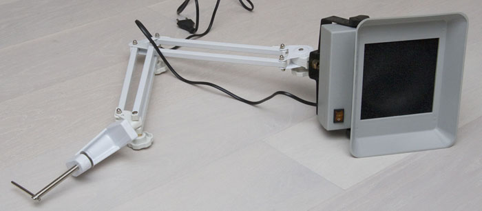
The next item in the toolbox was a normal table lamp. On the site "ChiD" I saw something called the "desk lamp shadowless fluorescent." Considering such an interesting name, as well as a rather big price, I expected to receive something in the High-Tech style, with decent quality. What was my disappointment when I was brought this very lamp ... Not only the quality of performance, but even the design and design solutions are so nightmarish that I could not seriously believe that it is being mass-produced! The switch broke after the third power-up, which led to the need to disassemble the lamp and even more marvel at the circuit solutions (there is not even a starter there, and the lamps are ignited by a mechanical switch, which you press when you turn it on - that is, while you press it with your finger filament voltage is applied). By the way, I looked at the manufacturer’s internet site - in general, this is a medical lamp intended for dentists ...
If I chose a soldering iron just by its appearance, then I approached the choice of a tool for stripping MGTP wires seriously - I used yandex. To my surprise, it became clear that such a tool simply does not exist! All existing tools simply cannot cope with fluoroplastic insulation, especially if the wire is thin. In childhood, our own teeth were successfully used for this, but now this option was no longer suitable. In the end, he stopped at the thermal method - at first the tip of the wire is heated by a soldering iron in rosin (so that a small drop of rosin remains on the wire), and then this tip is immersed for a couple of seconds in the melted solder. For this procedure, some experts recommended to modify the soldering iron tip, but I decided to go further and purchased a whole soldering bath. It sounds loud, but in reality it is a rather small thing, which, nevertheless, turned out to be almost perfect for my needs. After some experiments, the temperature was found at which a strictly necessary amount of wire was stripped almost independently of the dive time. In addition, the wire immediately turned out to be well tinned, which also accelerated the work. I believe that this decision has saved me a lot of time and nerves.

However, with this method of cleaning there is one unpleasant nuance: when heated above a certain temperature, the fluoroplast decomposes into components, among which is the chemical poisoning substance phosgene. Of course, I understood that the amount of these substances is such that even with a year of continuous stripping of wires, I could hardly get at least some dangerous amount of gas, but I didn’t feel like getting home odors. Therefore, I was happy to understand that this is a very good reason to buy another toy on the site "ChiD" - "Smoke absorber on a tripod." It's just a small exhaust fan that draws air through a replaceable carbon filter. In general, the device seemed to work fine - the level of smells from soldering and cleaning the wires when using a smoke absorber was actually much lower than without it. And by the end of the project, the white bloom on the filter also made me think that without the smoke absorber this bloom would have been in the air (and then in our lungs). The only thing - the noise level of the device is much higher than we would like. Especially considering that the smoke absorber was forced to be right next to my head, after a couple of hours my head was starting to swell up from the noise of the fan.
The last device I bought for this project was the chip programmer ChipProg-48. It is clear that one could get by with a much simpler and cheaper device (or simply assemble oneself, which I once did), but I wanted to get a device that could do everything. The product is Russian-made, it is done quite normally, the software also looks more or less. The beauty of the device is that there is practically no serial chip that this programmer cannot flash. And even if something completely new appears, updating the programmer software solves this problem.

Finally, the build process could begin. I decided to put all the chips in the sockets - the thought of the potential need to rewire a chip, to which 10 to 100 wires were soldered, didn’t inspire me (never liked redoing what was already done).
The first step was the installation of panels, connectors and blocking capacitors.It didn't take a lot of time, and before that the completely clean breadboard suddenly changed and became like something.
The next stage spread the power wires and installed 3 LEDs, indicating the presence of power on the processor. In general, I wanted to make it beautiful, so I decided to use the wire for power, which is noticeably thicker than necessary. Unfortunately, this did not add beauty, but created problems. Such a wire was not cleaned in a solder bath, so I had to use wire cutters, and that was a lot of wasted time. Yes, and the installation of such a wire is also more complicated than a thin MGTF. By the time it became clear, it was already too late to redo something, so I had to finish the job.
After installing the power wires, I checked the probe with the correctness of the connections and could not resist in order not to supply power to the board. Not only did not smoke anything, but even all three LEDs lit up, which additionally inspired - at least something earned!
Then went the process of installing the main wires. For this purpose, it used MGTF with a section of 0.05 sq. Mm, although, probably, it would be worth taking 0.03 - it would be even more fun. After mounting most of the wires, I realized that everything could be done on a board of a smaller size - there was a lot of empty space left. Although, in my opinion, it looks a little more interesting.

After finishing with almost all the wires connecting the chips, I installed the remaining elements - a small number of resistors, transistors and capacitors, as well as a power supply unit.
During the installation of the “dissipation” I added some more installation wires, and I was surprised to realize that the installation part of the process was finished on this.
To be honest, I somehow didn’t believe it, but the dialing of the address and data buses did not detect any errors in this part of the installation, I decided to check the rest at the launch stage.
It's time to use the programmer. It was necessary to program the microcircuit of the character generator 573RF2 and the monitor 573RF6. Unfortunately, the problem immediately popped up. With RF6, the programmer refused to work at all categorically - he stopped at the start of programming and reported a defective leg. Moreover, both the available chips behaved the same way. I didn’t understand completely what was the matter - the microcircuits are really faulty, the programmer is not working properly, or I am using the wrong programmer. I just went to the store and bought an imported microcircuit, which was flashed without any problems.
RF2 also had a similar problem. The programmer immediately declared a malfunctioning pin (although I don’t understand how to determine the malfunction of that particular input), but at the same time I programmed the chip, and checking the contents showed that the programming was successful.
After a hitch with the ROM, everything was ready to install the chips in the panel. As expected, the imported microcircuits in the imported panels became ideal, but the Russian cases with metric dimensions did not fit into the inch panels. However, this is a well-known and, more often, not a very serious problem.

Finally, the solemn moment of power. I understood that such a construction, assembled by wires on a breadboard, could not immediately make money in principle, so I did not even connect the video input of the TV. The main thing, after turning on the power, the smoke did not seem to come out of nowhere, well, well. Next, I took an oscilloscope and looked at the main signals on the processor. To my surprise, they looked like something working, so I decided to take a look at what is happening on the video output. The strangest thing is that on the video output, the oscilloscope showed the presence of a quite meaningful signal, with pulses of horizontal and vertical sweeps. Considering that in 86 a video signal is formed by a video controller requiring programming of settings, as well as participation in direct memory access, the presence of such a signal indicated thatthat a lot of things in the system (if not everything at all) work correctly. Not believing myself, I plugged in the TV and after a few seconds watched an inscription that I had repeatedly dreamed of in 1986 - “RADIO-86RK”, an arrow and a blinking cursor!
On the one hand, it was joyful, but, on the other hand, it was a little sad - the dream came true, which means it is no longer there. Maybe it was not necessary to tackle it at all, let it be so?
For sweet, I decided to give the device a little more finished look. At first I read how to cut plexiglas, then I bought a piece of plexiglass, a cutter, stands on the board and legs for radio devices in the same “ChiD” and let it all go.
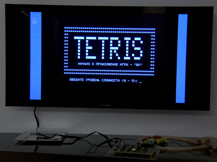
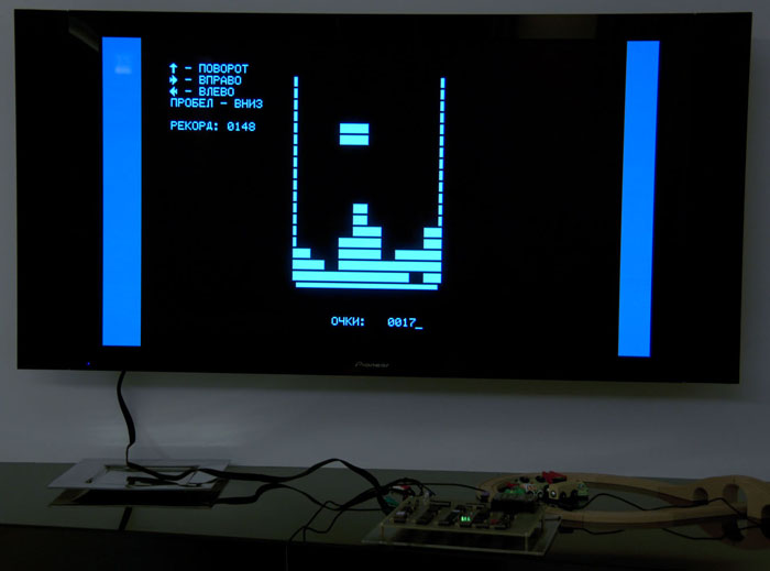
Well, to top it off, I wrote a single program on the ROM to demonstrate to my family that this is still a real computer!
Before that, I had already figured out a bit with microprocessor technology in a series of publications several years earlier in the same Radio about the construction of the Radio Micro 80 microcomputer. Unfortunately, the circuit design of the Micro 80 was extremely difficult (more than 200 microcircuits), so it was practically impossible for me to repeat it both because of the complexity of the construction and because it was impossible to get the details.
So for the time being, I could only write programs on machine codes in a notebook in a box and dream of a wizard in a helicopter of any color that suddenly gives me this very Micro 80.
The situation has to some extent changed after the publication of articles on Radio 86RK. 86RK was much simpler - it contained “only” 29 microcircuits. Only if before that I clearly understood that there was no chance at all, then there seemed to be an opportunity to get my own micro-computer theoretically, but in practice the issue with the details was almost unresolvable anyway.
')
I will explain a little - at that time everything was in short supply, and radio components were no exception to this rule. Moreover, many of the details, in principle, did not come in retail sales. Nevertheless, it was possible to get everything. In large cities, there were places (often near stores such as Young Technician, etc.) where it was worthwhile to stand with an absent minute or two, how did the “comrades” who were spinning nearby approach you and casually asked - “Is there anything you need? ". Naturally, such activity was completely illegal, and was regularly suppressed by the relevant law enforcement agencies. Also, as in any criminal business, there has always been a danger that you will purposefully be “thrown”, “scouted out” or “substituted” in general. Accordingly, to me, as a resident of a small village, this option was not very suitable - and logistically it was extremely complicated, and it was just scary. There were simply no other options (in the absence of relatives / acquaintances working in enterprises where there could be a nomenclature of parts required).
Therefore, my mood has only deteriorated - it is better to clearly know that it is impossible to do this than to constantly suffer, wondering if it is impossible to somehow dodge and find the necessary components. In such torments, a couple of years passed, I went to study at a university in one of the largest cities of the Union, and the ghost of 86 RC became more distinct. Having cooperated with a friend, we made a foray into the firm shop “Electronics”, easily attracted the attention of the “merchants” who were there and became owners of almost the complete set of everything necessary for assembling RK - from microchips to the board and keyboard buttons.
Then everything went somehow wrong. Now it is even difficult for me to understand / remember why we failed. The fact remains that the computer did not work.
I had many childhood dreams / desires of completely different scales and importance, and most of them came true. However, a couple of months ago, I suddenly realized that there seems to be one more unfulfilled, but firmly entrenched dream somewhere in the depths of consciousness - after all, to build Radio 86RK. And not to buy, but to build it yourself, and as close as possible to what I could have done more than 20 years ago.
By now, for almost 20 years, I have not taken a soldering iron and an oscilloscope in my hands, so that some of the skills that were available were undermined and forgotten. Nothing - I decided that it would even be more interesting.
First, it was necessary to decide on some basic things. First, the specific scheme of the device. It is clear that there is a very original scheme, published in Radio in 1986, but even to it later corrections / additions were repeatedly published. In addition, operative memory was one of the weakest points of the 86RK. In the base case, its volume was 16K (namely, sixteen KILobytes), and it was organized on 8 microcircuits 565RU3. Even the new RU3s did not work very reliably, and how the products of more than 20 years ago will work (the new ones, naturally, haven’t been released a long time ago) could surely be assumed. On the other hand, I really didn’t want to move away from the original - after all, it was possible to simply assemble an emulator on a FPGA or even AVR. Therefore, on the Internet, a scheme was found using modern SRAM memory. In addition to reducing the number of cases of the memory itself (instead of 16 RUUs for the 32K version, only one is needed), a pair of microcircuits were also thrown out, ensuring the operation of the old memory. However, everything else (including the memory address space) absolutely corresponded to the original, i.e. any programs for the original 86RK will be able to work on this version, even if they access hardware resources directly.
The second big decision was related to the choice of which board to do all this on. For the scheme found, there was also a very nice printed circuit board, which, moreover, could be bought. However, it seemed to me that it would be somehow dishonest - too simple. After all, it was possible to buy an assembled computer in the same place ... Therefore, it was decided to go, probably the most difficult way - a mock-up board with installation of MGTF wire.
Next you had to choose the power supply circuit. The options were from using the most original scheme (a pretty confused implementation of a classic power supply) to using a standard ATX format power supply. 86 (or rather, the microprocessor 58080) requires 3 supply voltages (+5, -5 and +12 V) and many power supplies from conventional PC-shki provide this. In the end, I decided to use a standard power module installed on the board. Something from 9 to 36 V is fed to the input of this type, we get three necessary voltages at the output, and even with the desired on / off sequence.
The last question I spent some time thinking about is what to do with the keyboard. So it was tempting to make a PCB, trying LUT (laser-iron technology) for the original keyboard, but, ultimately, it became interesting to understand a little about modern technologies too, so I decided to leave the PS / 2 keyboard adapter built on the ATMega 48 microcontroller. In fact, this adapter connects to the 86 and simulates the original 86 matrix keyboard, while on the other hand this adapter has the most common modern PC keyboard with PS / 2 interface (USB is much more difficult to implement). It is curious that the computing power of this microcontroller is noticeably higher than that of the entire 86RK computer ...
Finally, it's time to start buying different crap, figovin and garbage. I always liked it - as they say, equipment is most important. It does not matter that you do not know how to properly wear it, but you look cool! Yes, and there is a feeling that everything is ready and you can do everything :)
I have to say right away that the budget of the event did not bother me at all, the main thing was to spend the minimum of time and nerves on finding everything I needed. Therefore, it was decided to buy everything in the Chip and Dip online store. Just in case, everything was bought in double quantity - suddenly something broken or not working, but I just have a creative impulse! Basically, there were no major problems, although there were some overlays. But at the prices I can not speak out - probably, if I spent a little time and walked (virtually or physically) in other places, then 90% of the main components could be bought ten times cheaper - and this is not an exaggeration. The fact is, the microcircuits I need in modern conditions are practically not used, so the concept of "market price" for them is simply absent. So you can find them from “free” (just by searching on the relevant forums) to “Chip and Dip” (i.e., even strangely expensive - did they make a mistake in the currency there?). At the same time, I understand that this is the business of the store itself, and I am not complaining, just stating a fact.
In general, of course, the site "ChiD" - a terrible place. I think if in childhood I had the opportunity to purchase everything that my heart desires, then I would just have a heart failure. Even now it was difficult for me to break away from justifying myself, why I definitely need to buy more woo that garbage. The site itself is made quite normal and convenient, with a decent amount of information. At least, I didn’t see anything even closely resembling other Russian component sellers.
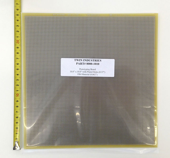
As already said, in order to reduce the hassle and save time, I found absolutely everything I needed in Chip and Dip. Everything, except for almost the most important thing - the breadboard. With some surprise, I found that the size of the board I needed (namely, I wanted at least 20x20 cm) could not be found anywhere at all. I had to turn to Google and after 10 minutes I ordered a 10x10 inch board from Twin Industries, USA. Taking into account the urgent forwarding, all this cost me the price of an inexpensive tablet, but so take a walk!
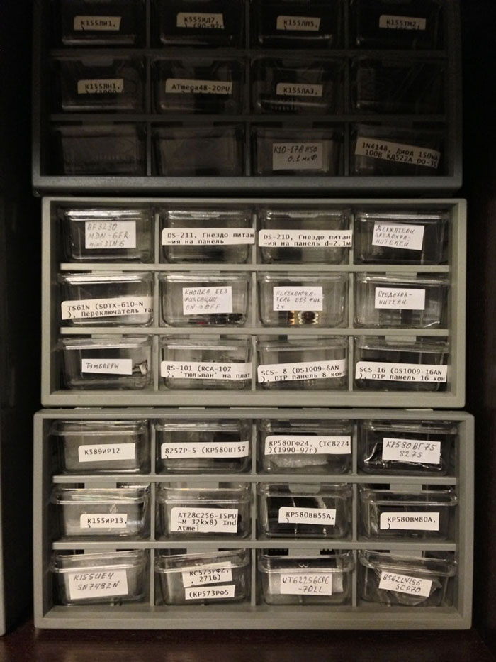
While I was dealing with boards, the first deliveries from Chip and Dip came. And again I can not speak out about the prices of some positions. To be where to store my treasures, I ordered several cassettes. The price initially seemed very overpriced, but there was a hope to get something completely glamorous for this money. Unfortunately, even my children's cassette box of matchboxes looked (and worked) better. I honestly do not understand how that ... you can even try to sell for that kind of money! And the matter is not only (and not so much) in appearance - workmanship and ergonomics of use are just horrible!
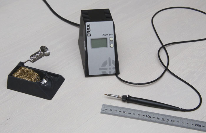
In addition to parts, I also needed tools, because my favorite 36V soldering iron disappeared without a trace somewhere in the whirlwind of perestroika. Having decided to start with a soldering iron, I realized how much has changed since my childhood. I didn’t conduct any special research on this topic, to be honest - I just looked into the store and chose from the shelf what I liked in appearance - namely, the ERSA i-CON pico soldering station. Already at home, I discovered how incomparably better this tool was of what had been encountered before. It is clear that you can set the temperature of the tip, which will be maintained with great accuracy even in the process of soldering. You can even download temperature maintenance curves from the SD card! True, I did not begin to understand why an ordinary person would need it, but it sounds cool! I would rather dwell on more obvious things that I directly felt on myself.
First, the size and weight of the soldering iron, as well as the quality of the cable is beyond praise. In the hands of a soldering iron almost does not feel, the cable is very flexible and heat-resistant - if you accidentally touch a sting, then there is no trace on the insulation at all. I think that the handle of my old soldering iron weighed more than the entire soldering iron from ERSA, and there is nothing to say about the cable - it was thick, hard, and when touched with a sting, it immediately melted and disgustedly smoked.
Secondly, the stinger warms up almost instantly (like writing about 9 seconds). The heating element is located almost inside the tip, so there is no loss of time for heating unnecessary parts, and the temperature of the tip is thus maintained disproportionately better. At the same time, there is no warming up of the handle of the soldering iron - after an hour of work my old soldering iron could not be held in hand, the handle was so heated. Here, it seems that the only source of warming the handle is the heat of my own fingers.
Thirdly, the broadest choice of stings, besides not fireproof. The choice is so wide that I could not finally decide what is more suitable for me for certain operations. By the way, changing the sting takes literally seconds. Burnability greatly saved time, and did not have to be distracted at the most inopportune moment to clean the sting. A small distraction - once in my childhood, repairing the TV and being immersed in it almost to the waist, thinking, I automatically tried to clean the soldering iron's sting by licking it with my tongue. For more than a week I could not eat anything solid ...
Fourth, I was struck by the power of this miniature soldering iron. An old soldering iron with a noticeably large size and three times more weight was 25 watts. When buying a soldering station, I didn’t even look at the power, deciding that for small parts 20 watts, which you can obviously count on, will be enough, but for bigger things, I will buy something more powerful. What was my surprise when I discovered that the power of this soldering iron 80 W! Therefore (with the use of appropriate tips) he could completely satisfy me in terms of soldering any imaginable parts.
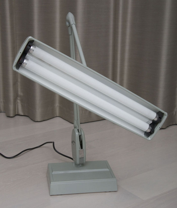
The next item in the toolbox was a normal table lamp. On the site "ChiD" I saw something called the "desk lamp shadowless fluorescent." Considering such an interesting name, as well as a rather big price, I expected to receive something in the High-Tech style, with decent quality. What was my disappointment when I was brought this very lamp ... Not only the quality of performance, but even the design and design solutions are so nightmarish that I could not seriously believe that it is being mass-produced! The switch broke after the third power-up, which led to the need to disassemble the lamp and even more marvel at the circuit solutions (there is not even a starter there, and the lamps are ignited by a mechanical switch, which you press when you turn it on - that is, while you press it with your finger filament voltage is applied). By the way, I looked at the manufacturer’s internet site - in general, this is a medical lamp intended for dentists ...
If I chose a soldering iron just by its appearance, then I approached the choice of a tool for stripping MGTP wires seriously - I used yandex. To my surprise, it became clear that such a tool simply does not exist! All existing tools simply cannot cope with fluoroplastic insulation, especially if the wire is thin. In childhood, our own teeth were successfully used for this, but now this option was no longer suitable. In the end, he stopped at the thermal method - at first the tip of the wire is heated by a soldering iron in rosin (so that a small drop of rosin remains on the wire), and then this tip is immersed for a couple of seconds in the melted solder. For this procedure, some experts recommended to modify the soldering iron tip, but I decided to go further and purchased a whole soldering bath. It sounds loud, but in reality it is a rather small thing, which, nevertheless, turned out to be almost perfect for my needs. After some experiments, the temperature was found at which a strictly necessary amount of wire was stripped almost independently of the dive time. In addition, the wire immediately turned out to be well tinned, which also accelerated the work. I believe that this decision has saved me a lot of time and nerves.
However, with this method of cleaning there is one unpleasant nuance: when heated above a certain temperature, the fluoroplast decomposes into components, among which is the chemical poisoning substance phosgene. Of course, I understood that the amount of these substances is such that even with a year of continuous stripping of wires, I could hardly get at least some dangerous amount of gas, but I didn’t feel like getting home odors. Therefore, I was happy to understand that this is a very good reason to buy another toy on the site "ChiD" - "Smoke absorber on a tripod." It's just a small exhaust fan that draws air through a replaceable carbon filter. In general, the device seemed to work fine - the level of smells from soldering and cleaning the wires when using a smoke absorber was actually much lower than without it. And by the end of the project, the white bloom on the filter also made me think that without the smoke absorber this bloom would have been in the air (and then in our lungs). The only thing - the noise level of the device is much higher than we would like. Especially considering that the smoke absorber was forced to be right next to my head, after a couple of hours my head was starting to swell up from the noise of the fan.
The last device I bought for this project was the chip programmer ChipProg-48. It is clear that one could get by with a much simpler and cheaper device (or simply assemble oneself, which I once did), but I wanted to get a device that could do everything. The product is Russian-made, it is done quite normally, the software also looks more or less. The beauty of the device is that there is practically no serial chip that this programmer cannot flash. And even if something completely new appears, updating the programmer software solves this problem.
Finally, the build process could begin. I decided to put all the chips in the sockets - the thought of the potential need to rewire a chip, to which 10 to 100 wires were soldered, didn’t inspire me (never liked redoing what was already done).
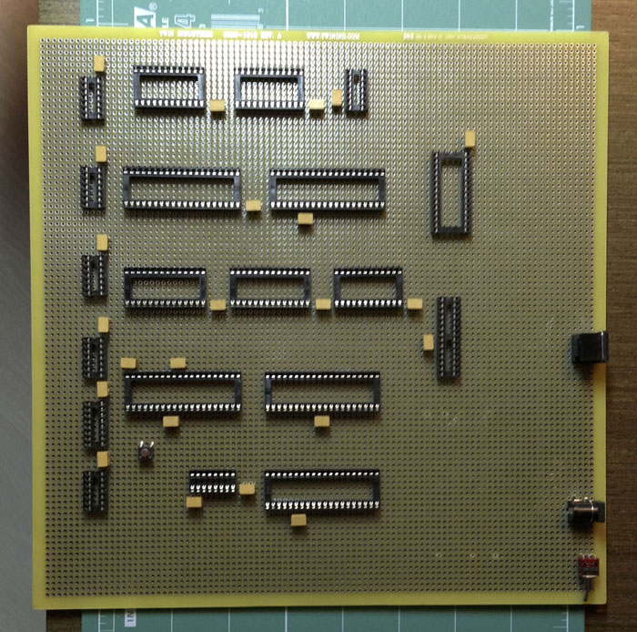
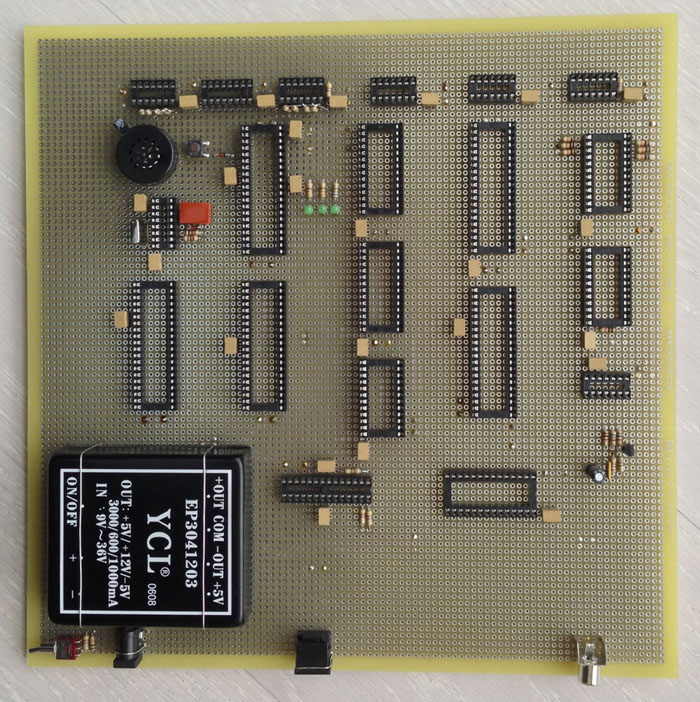
The first step was the installation of panels, connectors and blocking capacitors.It didn't take a lot of time, and before that the completely clean breadboard suddenly changed and became like something.
The next stage spread the power wires and installed 3 LEDs, indicating the presence of power on the processor. In general, I wanted to make it beautiful, so I decided to use the wire for power, which is noticeably thicker than necessary. Unfortunately, this did not add beauty, but created problems. Such a wire was not cleaned in a solder bath, so I had to use wire cutters, and that was a lot of wasted time. Yes, and the installation of such a wire is also more complicated than a thin MGTF. By the time it became clear, it was already too late to redo something, so I had to finish the job.
After installing the power wires, I checked the probe with the correctness of the connections and could not resist in order not to supply power to the board. Not only did not smoke anything, but even all three LEDs lit up, which additionally inspired - at least something earned!
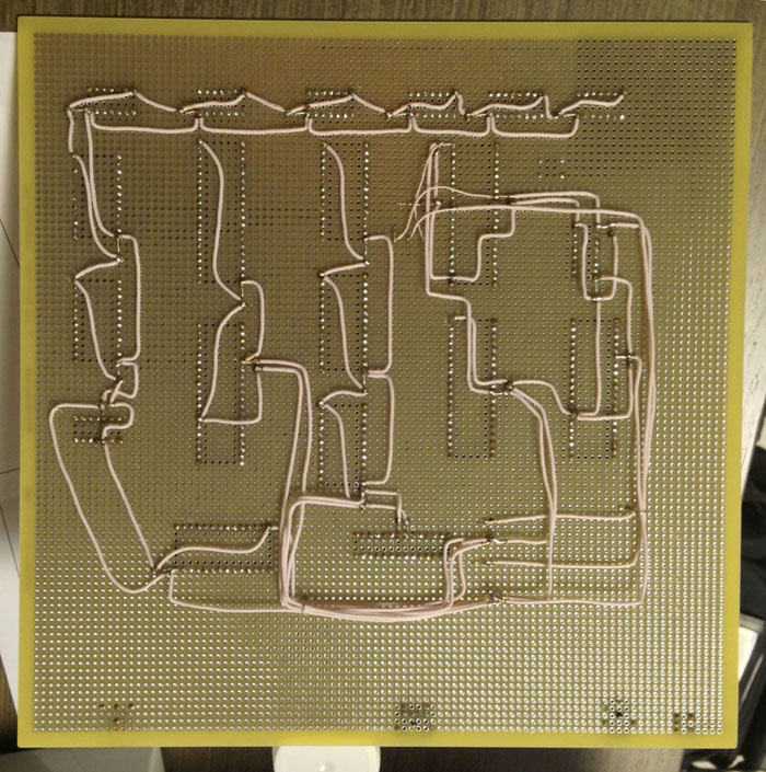
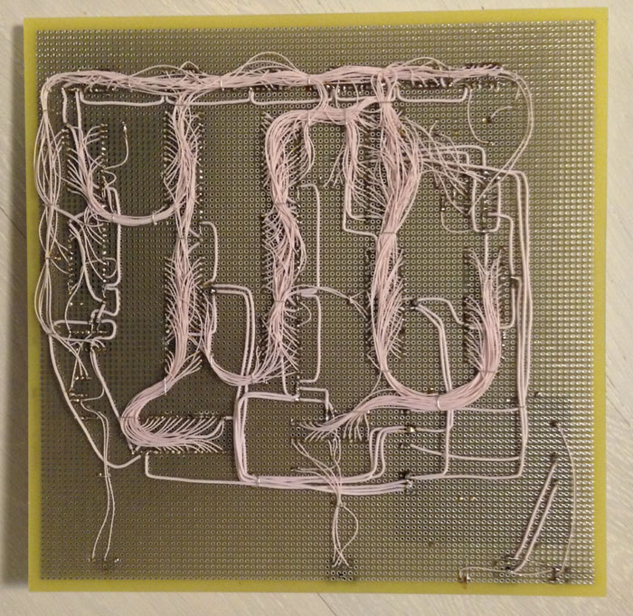
Then went the process of installing the main wires. For this purpose, it used MGTF with a section of 0.05 sq. Mm, although, probably, it would be worth taking 0.03 - it would be even more fun. After mounting most of the wires, I realized that everything could be done on a board of a smaller size - there was a lot of empty space left. Although, in my opinion, it looks a little more interesting.
After finishing with almost all the wires connecting the chips, I installed the remaining elements - a small number of resistors, transistors and capacitors, as well as a power supply unit.
During the installation of the “dissipation” I added some more installation wires, and I was surprised to realize that the installation part of the process was finished on this.
To be honest, I somehow didn’t believe it, but the dialing of the address and data buses did not detect any errors in this part of the installation, I decided to check the rest at the launch stage.
It's time to use the programmer. It was necessary to program the microcircuit of the character generator 573RF2 and the monitor 573RF6. Unfortunately, the problem immediately popped up. With RF6, the programmer refused to work at all categorically - he stopped at the start of programming and reported a defective leg. Moreover, both the available chips behaved the same way. I didn’t understand completely what was the matter - the microcircuits are really faulty, the programmer is not working properly, or I am using the wrong programmer. I just went to the store and bought an imported microcircuit, which was flashed without any problems.
RF2 also had a similar problem. The programmer immediately declared a malfunctioning pin (although I don’t understand how to determine the malfunction of that particular input), but at the same time I programmed the chip, and checking the contents showed that the programming was successful.
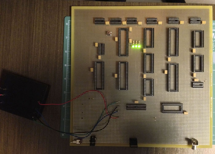
After a hitch with the ROM, everything was ready to install the chips in the panel. As expected, the imported microcircuits in the imported panels became ideal, but the Russian cases with metric dimensions did not fit into the inch panels. However, this is a well-known and, more often, not a very serious problem.
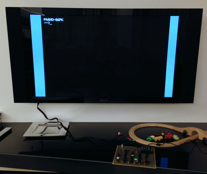
Finally, the solemn moment of power. I understood that such a construction, assembled by wires on a breadboard, could not immediately make money in principle, so I did not even connect the video input of the TV. The main thing, after turning on the power, the smoke did not seem to come out of nowhere, well, well. Next, I took an oscilloscope and looked at the main signals on the processor. To my surprise, they looked like something working, so I decided to take a look at what is happening on the video output. The strangest thing is that on the video output, the oscilloscope showed the presence of a quite meaningful signal, with pulses of horizontal and vertical sweeps. Considering that in 86 a video signal is formed by a video controller requiring programming of settings, as well as participation in direct memory access, the presence of such a signal indicated thatthat a lot of things in the system (if not everything at all) work correctly. Not believing myself, I plugged in the TV and after a few seconds watched an inscription that I had repeatedly dreamed of in 1986 - “RADIO-86RK”, an arrow and a blinking cursor!
On the one hand, it was joyful, but, on the other hand, it was a little sad - the dream came true, which means it is no longer there. Maybe it was not necessary to tackle it at all, let it be so?
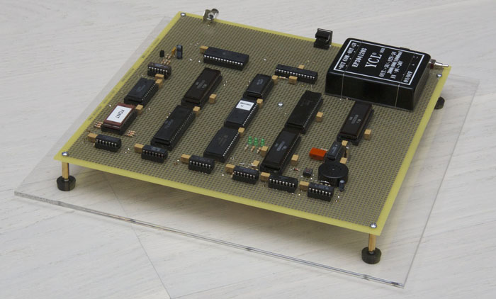
For sweet, I decided to give the device a little more finished look. At first I read how to cut plexiglas, then I bought a piece of plexiglass, a cutter, stands on the board and legs for radio devices in the same “ChiD” and let it all go.
Well, to top it off, I wrote a single program on the ROM to demonstrate to my family that this is still a real computer!
Source: https://habr.com/ru/post/202010/
All Articles