In the world of contours CorelDRAW
The Contour effect creates concentric outlines outside or inside the base shapes, curves, or text. When an effect is associated with an object, the latter becomes the manager, and the new forms become the Contour group. Changes made to the original object immediately affect the related group. After the Contour group is selected, its properties can be changed at any time.
You can apply and customize the Contour effect in different ways. The effect is assigned using the appropriate tool or in the docker window. The setting can be done with interactive markers or buttons on the attribute panel.
To create an effect with the tool, you need to select the source object, then select the Contour tool (Figure 1).

Fig. 1. The Contour tool is applied to the selected pentagon. Pointer changed (right)
As a result, the mouse pointer changes, and the corresponding controls appear in the attributes panel. You must click on the object and drag the pointer in the desired direction. Moving the pointer into the object (Fig. 2a) will create the inner contour of the Inside Contour , dragging in the opposite direction (Fig. 2b) will create the outer contour of the Outside Contour .
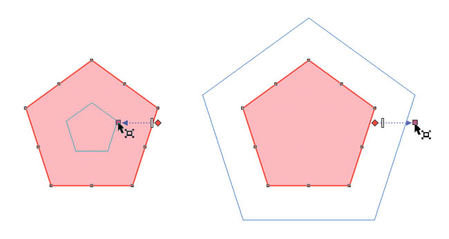
Fig. 2. Creating an internal (a) and external (b) contour
To create a contour with a docked window (docker), you need to select the object, select the desired settings, and then click the Apply button. In this case, you do not need to drag the mouse pointer. The Contour Effect will be built immediately after pressing this button (Fig. 3).
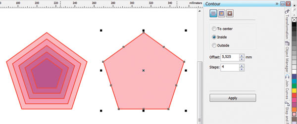
Fig. 3. Creating an internal contour with a docked window. Left - the result of applying the effect Contour
CorelDRAW offers three types of contour: To Center (Center), Inside Contour ( Outside ) and Outside Contour (Outside). The first two types create a contour inside the object, the third around the object. The contour to the center is created in such a way that the created figures fill the whole object (Fig. 4b), it is allowed to adjust only the distances between the figures. When creating an internal contour, you can adjust both the number of figures and the distance between them (Fig. 4d).

Fig. 4. The source object (a) and the result of creating three types of contour: To Center (b); Outside Contour (in); Inside Contour (g)
To switch between the contour types, use the corresponding buttons on the tool properties panel or checkboxes in the window.
')
It is possible to customize an already created contour interactively with the help of markers and a slider or using the buttons on the attributes panel. The second method is the most universal, since the property bar has access to all the elements of the effect. But the interactive markers and the slider can only change the number of shapes in the contour group and the distance between them.
To change the number of figures in the group at the inner contour, drag the square marker: inside the figure - to increase the number of objects (Fig. 5a) and outside - to reduce their number (Fig. 5b).
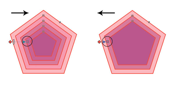
Fig. 5. Changing the number of figures at the inner contour with a square marker: a - increase, b - decrease
To change the number of figures in the outer contour group, a square marker should be dragged in the opposite direction: outwards - to increase the number of figures (Fig. 6a), inwards - to reduce their number (Fig. 6b).
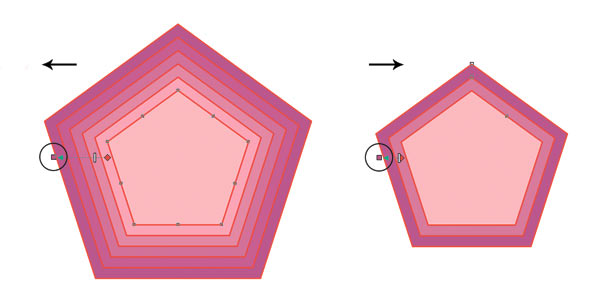
Fig. 6. The change in the number of figures in the outer contour: a - increase, b - decrease
To change the distance between the group of figures, use the white slider. To decrease the distance, move the slider to the right for the inner contour (7a) and to the left for the outer contour (7b). At the same time the number of figures changes automatically.
In order to independently influence these two parameters, the corresponding buttons on the attributes panel are used: Contour Steps to set the number of figures in the group (this parameter is not available for the contour To the center) and Contour offset to set the distance between the figures in the group .
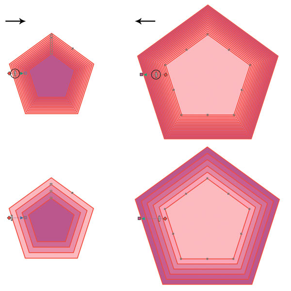
Fig. 7. Reducing the distance between the figures in the group: a - for the inner contour, b - for the outer contour
The color result of the effect depends on both the fill color and outline (outline) of the original object, as well as the fill color and outline of the Outline tool itself. To adjust the effect colors, use the buttons on the attribute panel. If the colors of the effect coincide with the colors of the original object, we get the simplest effect (Fig. 8a). If the colors of the effect and the original shape do not match, the group of shapes of the contour is smoothly repainted from the source to the final color (Fig. 8b, c).
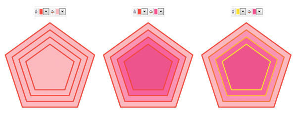
Fig. 8. Examples of setting the color of the Contour effect (b, c). The original figure (a) has a red outline and a uniform pink fill.
If the source object has a gradient fill, then two colors will be available for the fill in the attributes panel. In fig. 9 shows examples of setting this type of fill.
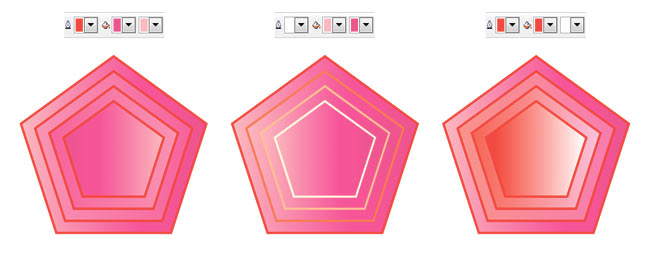
Fig. 9. Examples of setting the color of the Contour effect (b, c). The original figure (a) has a red outline and a fountain fill: a linear gradient from pink to crimson
It is important to remember the next moment - the Contour effect sets the fill and the contour only if the original object has those. For example, if the source object has a contour but does not have a fill, the Contour effect will also contain only the setting for the contour.
Similar to the Blend effect for the Contour, you can set the options for blending the color spectrum: direct (Fig. 10a), clockwise (Fig. 10b) and counterclockwise (Fig. 10c).
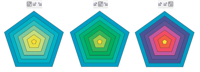
Fig. 10. Variants of color spectrum flowing: direct (a), clockwise (b), counterclockwise (c)
Like Blending , the Contour effect has an acceleration setting that allows you to achieve unequal gaps between the shapes of the outline group and the color shift towards the colors of the original (Fig. 11b) or final (Fig. 11c) object. To do this, remove the connection between the color and the object, which will allow you to adjust the acceleration of color and objects independently of each other.

Fig. 11. Examples of setting the Contour acceleration: a - the acceleration of color and objects are connected; b - the acceleration of objects is shifted towards the original object; c - color acceleration is shifted towards the final object
By default, all changes made to the source object immediately affect the related group. But if you want to independently configure the control object from the contour group, this connection needs to be broken. To do this, select the objects and press the key combination Ctrl + K or execute the command Arrange (→ Arrange) → Break Contour Group Apart (Disconnect the contour group). When separating the contour from the control object, the contour group is treated as one object. To customize the figures included in the group separately, you must ungroup them. So it was done in Fig. 12 before repainting three pentagons from the contour group.
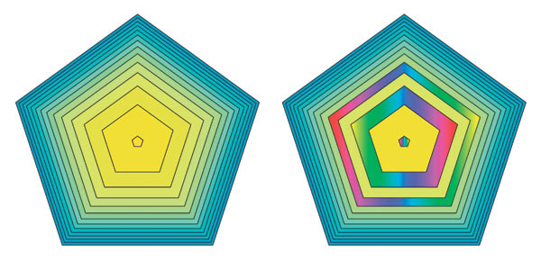
Fig. 12. For repainting three objects from the contour group, the contour was separated from the control object. Left - the initial effect
By specifying a small number of contour steps, a “tape” effect is obtained, which can be applied, for example, when imitating depth or drawing temperature maps. In fig. 13 is an illustration of a map of the depths of Lake Baikal. The image of the lake consists of three objects, two of which have a Contour effect with the number of steps 2, at the contour of the lower object the number of steps is increased to 3.
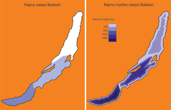
Fig. 13. The Contour effect with a small number of steps creates a step-by-step transition between colors (in this case, between shades of blue): a is the initial fill with solid colors, b is an example with a contour effect
As the number of steps increases, a smooth transition from one color to another appears, which can be used to simulate volume. Consider an example of drawing an apple using a different number of steps of the Contour effect:
1. First draw two intersecting ovals and group them. This form will have our future apple (Fig. 14a).
2. Use an outer contour for ovals with a step of 1 and with an offset of 57 mm to get the shape of an apple, but without internal intersections (Fig. 14b).
3. Separate the contour from the control object (Ctrl + K) and delete the control object (Fig. 14c).
4. Paint the resulting shape with a solid red fill, delete the outline (outline) of the object (Fig. 14d).
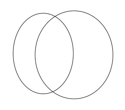

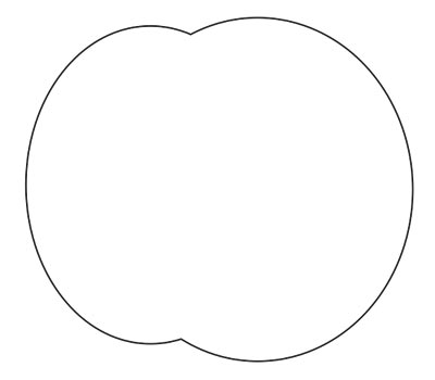

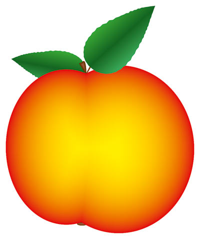
Fig. 14. Apple drawing scheme: a - two intersecting ovals are created; b - an external contour with a step of 1 is applied to the group; c - the contour and the control object are disconnected, the original object is deleted; g - the resulting figure is shaded in red, the outline (outline) is deleted; d - the inner contour of yellow color with a large number of steps is applied to the figure
5. We apply to the figure an internal contour with a large number of steps and a minimum offset. Set the outline color to yellow. If you are not satisfied with the option of moving from red to yellow color, obtained automatically, you can adjust it by changing the color and object acceleration. But do not forget to break the connection between them. In the example, the object's acceleration slider was shifted to the left. Finish the leaves and stem (Fig. 14e).
Using a large number of steps and an insignificant amount of displacement, using the Contour tool you can also draw a shadow or glow of the object (Fig. 15a, b).

Fig. 15. The outer contour was used for the image of shadow and luminescence: a - for shadow: the number of steps is 900, the displacement is 0.025 mm; b — for luminescence: the number of steps is 100, the offset is 0.125 mm
Direction of the contour To the center (To center) is ideal for drawing a target in compliance with the requirements of the International Federation of Sports Shooting: “unit” - 500 mm, black “apple” - 200 mm, the distance between the lines - 25 mm.
1. Draw a circle with a diameter of 500 mm. Adjust the color of the outline - black, fill color - white (Fig. 16a).
2. Apply a contour effect To the center (To center) with an offset value of 25 mm. The tool will automatically determine the number of steps (Fig. 16b).
3. Separate the contour effect from the control object and ungroup the objects. Select four inner circles and repaint the color of the outline and fill for them: the outline is white, the fill is black (Fig. 16c).
4. Put the numbers (Fig. 16g).
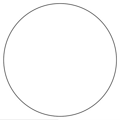


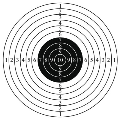
Fig. 16. Target drawing scheme: a - a circle with a diameter of 500 mm with a white fill and black outline was created; b - the effect of the contour To the center is applied; c - for the four inner circles, the colors of the outline and fillings on the opposite ones are changed; g - numbers
The same kind of contour with a small number of steps and an offset of several millimeters can be used to draw game mazes. By slightly editing the constructed contour, you can get, for example, the maze presented in fig. 17b.

Fig. 17. An example of a labyrinth created on the basis of the effect of the contour To the center: a - the stages of the construction of the labyrinth; b - final figure
As mentioned earlier, if the source object does not have a fill color set, then the group of contour objects will also not have a fill. This property of the effect was used to create the example in fig. 18. The contours of the objects are brown lines, repeating the shape of a seagull and text. The contour is applied directly to the text; it was not pre-converted to curves. To create the effect of translucent letters, a copy of the text was created, shaded with a solid color of dark brown color, and linear interactive transparency was applied to it.
Note that the outer contour has one very interesting feature. Unlike internal circuits, it can be applied to an open path. Moreover, if the offset value is greater than the thickness of the curve, then by specifying the fill of the contour, you can create the impression that the resulting shape has a fill, although in reality it is just an open curve that, in principle, cannot be filled (Fig. 19).
To copy the Contour effect, use the Copy contour properties button on the tool attribute panel or the Effects → Copy Effect → Contour From command. You must select an object to which you want to apply the effect. Press the button or execute the command, and then click the thick black arrow that appears on the object from which you are going to copy the effect. In this way in Fig. 18, the effect was copied from the gull image to the text, and then the result obtained slightly increased the number of contour steps.
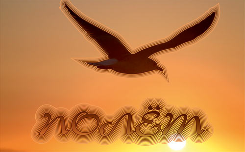
Fig. 18. The created Contour effect has no fill, the color changes only in the outline of the contour group.

Fig. 19. The outer contour is applied to the open path: a - the original open curve with a thickness of 2 mm; b - the result of the external contour with a step of 1 and a shift of 2 mm; - external contour with the number of steps 1 and offset 4 mm
Many of the examples given here could also be obtained using the Flow tool, such as an apple, a target, or a shadow with a glow. But for creating an internal shading for an object, the Blend tool is not very suitable. In fig. 20 shows two examples using both effects. To the inscription in Fig. 20a, the Contour effect was applied with the direction To the center (To center) and with a small offset value of 0.4 mm. As a result, we got what we wanted. But in fig. 20b flowed from large to small. As you can see, the effect is concentrated inside the larger label, and intermediate objects of overflow are disproportionately scaled. It turns out that to create smoothly shaded objects, it is necessary to use an internal contour with a large number of steps and a small offset value or contour To the center with an offset value less than 1 mm.

Fig. 20. The Contour tool (a) is ideal for creating internal shading of an object, while the Flow tool disproportionately scales parts of intermediate objects (b)
Based on COREL Magazine
Contour Application
You can apply and customize the Contour effect in different ways. The effect is assigned using the appropriate tool or in the docker window. The setting can be done with interactive markers or buttons on the attribute panel.
To create an effect with the tool, you need to select the source object, then select the Contour tool (Figure 1).
Fig. 1. The Contour tool is applied to the selected pentagon. Pointer changed (right)
As a result, the mouse pointer changes, and the corresponding controls appear in the attributes panel. You must click on the object and drag the pointer in the desired direction. Moving the pointer into the object (Fig. 2a) will create the inner contour of the Inside Contour , dragging in the opposite direction (Fig. 2b) will create the outer contour of the Outside Contour .
Fig. 2. Creating an internal (a) and external (b) contour
To create a contour with a docked window (docker), you need to select the object, select the desired settings, and then click the Apply button. In this case, you do not need to drag the mouse pointer. The Contour Effect will be built immediately after pressing this button (Fig. 3).
Fig. 3. Creating an internal contour with a docked window. Left - the result of applying the effect Contour
Contour types
CorelDRAW offers three types of contour: To Center (Center), Inside Contour ( Outside ) and Outside Contour (Outside). The first two types create a contour inside the object, the third around the object. The contour to the center is created in such a way that the created figures fill the whole object (Fig. 4b), it is allowed to adjust only the distances between the figures. When creating an internal contour, you can adjust both the number of figures and the distance between them (Fig. 4d).
Fig. 4. The source object (a) and the result of creating three types of contour: To Center (b); Outside Contour (in); Inside Contour (g)
To switch between the contour types, use the corresponding buttons on the tool properties panel or checkboxes in the window.
')
Contour setting
It is possible to customize an already created contour interactively with the help of markers and a slider or using the buttons on the attributes panel. The second method is the most universal, since the property bar has access to all the elements of the effect. But the interactive markers and the slider can only change the number of shapes in the contour group and the distance between them.
To change the number of figures in the group at the inner contour, drag the square marker: inside the figure - to increase the number of objects (Fig. 5a) and outside - to reduce their number (Fig. 5b).
Fig. 5. Changing the number of figures at the inner contour with a square marker: a - increase, b - decrease
To change the number of figures in the outer contour group, a square marker should be dragged in the opposite direction: outwards - to increase the number of figures (Fig. 6a), inwards - to reduce their number (Fig. 6b).
Fig. 6. The change in the number of figures in the outer contour: a - increase, b - decrease
To change the distance between the group of figures, use the white slider. To decrease the distance, move the slider to the right for the inner contour (7a) and to the left for the outer contour (7b). At the same time the number of figures changes automatically.
In order to independently influence these two parameters, the corresponding buttons on the attributes panel are used: Contour Steps to set the number of figures in the group (this parameter is not available for the contour To the center) and Contour offset to set the distance between the figures in the group .
Fig. 7. Reducing the distance between the figures in the group: a - for the inner contour, b - for the outer contour
Customize Outline Color
The color result of the effect depends on both the fill color and outline (outline) of the original object, as well as the fill color and outline of the Outline tool itself. To adjust the effect colors, use the buttons on the attribute panel. If the colors of the effect coincide with the colors of the original object, we get the simplest effect (Fig. 8a). If the colors of the effect and the original shape do not match, the group of shapes of the contour is smoothly repainted from the source to the final color (Fig. 8b, c).
Fig. 8. Examples of setting the color of the Contour effect (b, c). The original figure (a) has a red outline and a uniform pink fill.
If the source object has a gradient fill, then two colors will be available for the fill in the attributes panel. In fig. 9 shows examples of setting this type of fill.
Fig. 9. Examples of setting the color of the Contour effect (b, c). The original figure (a) has a red outline and a fountain fill: a linear gradient from pink to crimson
It is important to remember the next moment - the Contour effect sets the fill and the contour only if the original object has those. For example, if the source object has a contour but does not have a fill, the Contour effect will also contain only the setting for the contour.
Similar to the Blend effect for the Contour, you can set the options for blending the color spectrum: direct (Fig. 10a), clockwise (Fig. 10b) and counterclockwise (Fig. 10c).
Fig. 10. Variants of color spectrum flowing: direct (a), clockwise (b), counterclockwise (c)
Contour Acceleration
Like Blending , the Contour effect has an acceleration setting that allows you to achieve unequal gaps between the shapes of the outline group and the color shift towards the colors of the original (Fig. 11b) or final (Fig. 11c) object. To do this, remove the connection between the color and the object, which will allow you to adjust the acceleration of color and objects independently of each other.
Fig. 11. Examples of setting the Contour acceleration: a - the acceleration of color and objects are connected; b - the acceleration of objects is shifted towards the original object; c - color acceleration is shifted towards the final object
Separation of the contour from the control object
By default, all changes made to the source object immediately affect the related group. But if you want to independently configure the control object from the contour group, this connection needs to be broken. To do this, select the objects and press the key combination Ctrl + K or execute the command Arrange (→ Arrange) → Break Contour Group Apart (Disconnect the contour group). When separating the contour from the control object, the contour group is treated as one object. To customize the figures included in the group separately, you must ungroup them. So it was done in Fig. 12 before repainting three pentagons from the contour group.
Fig. 12. For repainting three objects from the contour group, the contour was separated from the control object. Left - the initial effect
Remove Contour Effect
By specifying a small number of contour steps, a “tape” effect is obtained, which can be applied, for example, when imitating depth or drawing temperature maps. In fig. 13 is an illustration of a map of the depths of Lake Baikal. The image of the lake consists of three objects, two of which have a Contour effect with the number of steps 2, at the contour of the lower object the number of steps is increased to 3.
Fig. 13. The Contour effect with a small number of steps creates a step-by-step transition between colors (in this case, between shades of blue): a is the initial fill with solid colors, b is an example with a contour effect
As the number of steps increases, a smooth transition from one color to another appears, which can be used to simulate volume. Consider an example of drawing an apple using a different number of steps of the Contour effect:
1. First draw two intersecting ovals and group them. This form will have our future apple (Fig. 14a).
2. Use an outer contour for ovals with a step of 1 and with an offset of 57 mm to get the shape of an apple, but without internal intersections (Fig. 14b).
3. Separate the contour from the control object (Ctrl + K) and delete the control object (Fig. 14c).
4. Paint the resulting shape with a solid red fill, delete the outline (outline) of the object (Fig. 14d).
Fig. 14. Apple drawing scheme: a - two intersecting ovals are created; b - an external contour with a step of 1 is applied to the group; c - the contour and the control object are disconnected, the original object is deleted; g - the resulting figure is shaded in red, the outline (outline) is deleted; d - the inner contour of yellow color with a large number of steps is applied to the figure
5. We apply to the figure an internal contour with a large number of steps and a minimum offset. Set the outline color to yellow. If you are not satisfied with the option of moving from red to yellow color, obtained automatically, you can adjust it by changing the color and object acceleration. But do not forget to break the connection between them. In the example, the object's acceleration slider was shifted to the left. Finish the leaves and stem (Fig. 14e).
Using a large number of steps and an insignificant amount of displacement, using the Contour tool you can also draw a shadow or glow of the object (Fig. 15a, b).
Fig. 15. The outer contour was used for the image of shadow and luminescence: a - for shadow: the number of steps is 900, the displacement is 0.025 mm; b — for luminescence: the number of steps is 100, the offset is 0.125 mm
Direction of the contour To the center (To center) is ideal for drawing a target in compliance with the requirements of the International Federation of Sports Shooting: “unit” - 500 mm, black “apple” - 200 mm, the distance between the lines - 25 mm.
1. Draw a circle with a diameter of 500 mm. Adjust the color of the outline - black, fill color - white (Fig. 16a).
2. Apply a contour effect To the center (To center) with an offset value of 25 mm. The tool will automatically determine the number of steps (Fig. 16b).
3. Separate the contour effect from the control object and ungroup the objects. Select four inner circles and repaint the color of the outline and fill for them: the outline is white, the fill is black (Fig. 16c).
4. Put the numbers (Fig. 16g).
Fig. 16. Target drawing scheme: a - a circle with a diameter of 500 mm with a white fill and black outline was created; b - the effect of the contour To the center is applied; c - for the four inner circles, the colors of the outline and fillings on the opposite ones are changed; g - numbers
The same kind of contour with a small number of steps and an offset of several millimeters can be used to draw game mazes. By slightly editing the constructed contour, you can get, for example, the maze presented in fig. 17b.
Fig. 17. An example of a labyrinth created on the basis of the effect of the contour To the center: a - the stages of the construction of the labyrinth; b - final figure
As mentioned earlier, if the source object does not have a fill color set, then the group of contour objects will also not have a fill. This property of the effect was used to create the example in fig. 18. The contours of the objects are brown lines, repeating the shape of a seagull and text. The contour is applied directly to the text; it was not pre-converted to curves. To create the effect of translucent letters, a copy of the text was created, shaded with a solid color of dark brown color, and linear interactive transparency was applied to it.
Note that the outer contour has one very interesting feature. Unlike internal circuits, it can be applied to an open path. Moreover, if the offset value is greater than the thickness of the curve, then by specifying the fill of the contour, you can create the impression that the resulting shape has a fill, although in reality it is just an open curve that, in principle, cannot be filled (Fig. 19).
Contour copy
To copy the Contour effect, use the Copy contour properties button on the tool attribute panel or the Effects → Copy Effect → Contour From command. You must select an object to which you want to apply the effect. Press the button or execute the command, and then click the thick black arrow that appears on the object from which you are going to copy the effect. In this way in Fig. 18, the effect was copied from the gull image to the text, and then the result obtained slightly increased the number of contour steps.
Fig. 18. The created Contour effect has no fill, the color changes only in the outline of the contour group.
Fig. 19. The outer contour is applied to the open path: a - the original open curve with a thickness of 2 mm; b - the result of the external contour with a step of 1 and a shift of 2 mm; - external contour with the number of steps 1 and offset 4 mm
Flowing or Contour?
Many of the examples given here could also be obtained using the Flow tool, such as an apple, a target, or a shadow with a glow. But for creating an internal shading for an object, the Blend tool is not very suitable. In fig. 20 shows two examples using both effects. To the inscription in Fig. 20a, the Contour effect was applied with the direction To the center (To center) and with a small offset value of 0.4 mm. As a result, we got what we wanted. But in fig. 20b flowed from large to small. As you can see, the effect is concentrated inside the larger label, and intermediate objects of overflow are disproportionately scaled. It turns out that to create smoothly shaded objects, it is necessary to use an internal contour with a large number of steps and a small offset value or contour To the center with an offset value less than 1 mm.
Fig. 20. The Contour tool (a) is ideal for creating internal shading of an object, while the Flow tool disproportionately scales parts of intermediate objects (b)
Based on COREL Magazine
Source: https://habr.com/ru/post/201890/
All Articles