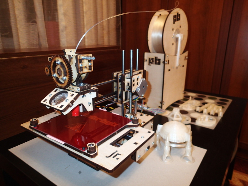
A Tale of the Present PRINTRBOT (Part 3: Trial by Fire)
A few weeks have passed since the last post about the present Printrbot, but the time has not passed for nothing.
During this arbitrary printing failure was mercilessly defeated, the reel rod upgrade was made and several items for the soul.
And with a new power for the pen ...
In the previous parts, we practically collected our 3D printer ( Part 1 ) and came close to calibrating it ( Part 2 ).
Here I’ll start right now with her. And there, God willing, we will have time to test, but Bolivar will not endure the quadruple part ...
Although, it would be possible to talk a little more about the nuances of the assembly, but looking at the previous material with a critical eye, I can say with confidence that most of the really important points have already been covered. All the rest is quite fit into the model: “Do not feel sorry for glue!” Perhaps, in the process of the third part, something else will emerge, let's see ...
My dear!))
')
That's right, and let's start with the desktop.
The desktop at Printer bot is correct!
In general, the desktop at the household 3D-printer should be spring-loaded. Those. must have some move down the z axis.
What for? And just so that the calibration process along the Z axis does not turn into a periodic migraine for you. The fact is that no matter what materials a household 3D printer is created from - the table will “float”, warp and shift in different ways relative to the position. We are talking about tenths of a millimeter, but these are exactly the shares that are responsible for the quality of the model's sticking to the table and the quality of the bottom surface, especially its faces and the faces of the holes in it, if any.
Those. already for two main parameters!
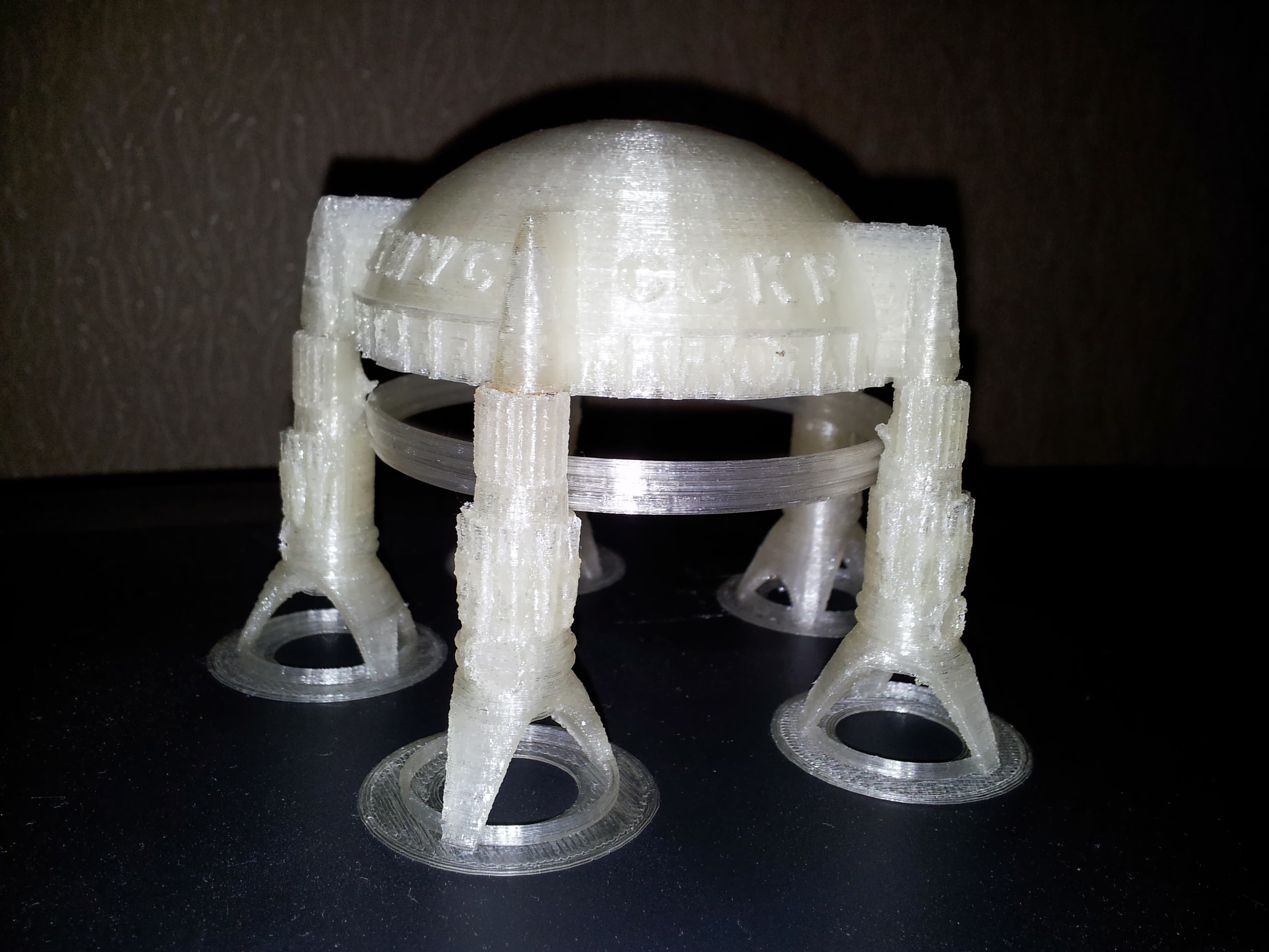
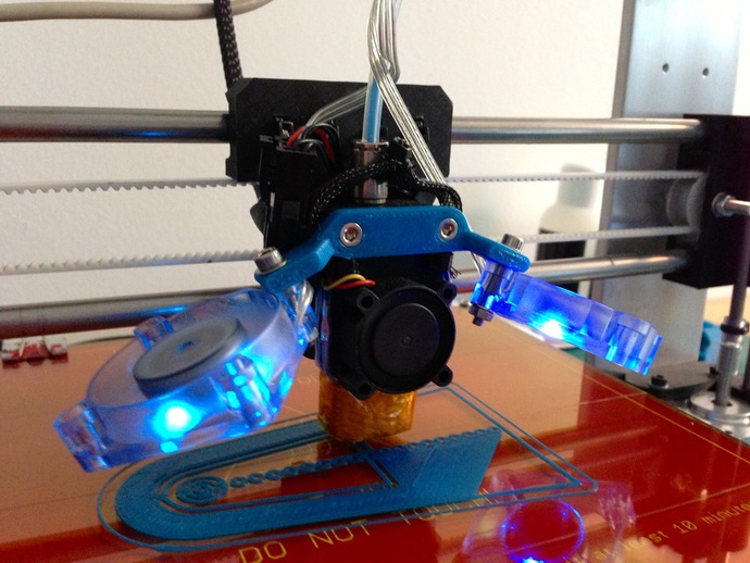
For example, to print a similar rocket with a three-toed base without a hot table is unlikely to succeed, even with heating I had to add stiffeners and a half-millimeter ring at the base to increase the contact area.
Khius. The first Soviet photonic airplane, which was commanded by Anatoly Borisovich Yermakov in September 1991. for the first time he made a successful landing on the planet Venus and delivered a Soviet scientific expedition to the area of Uranova Golkonda. It was the first space flight of Alexei Bykov, a “desert specialist”. The expedition also included geologist Grigori Dauge, pilot Bogdan Spitsyn, navigator Mikhail Krutikov and geologist Vladimir Yurkovsky. Spitsyn and Ermakov died.
In memory of the dead, fifty kilometers to the south of Golkonda, at the spurs of the ridge, in the center, now a city, a monument was erected - the “Boy” tank transporter. They found him, cut him out of the soil and so, together with the melted stone, put him on a plastic base. A short inscription was carved on the armor: “First”. This is a monument to Anatoly Yermakov, Bogdan Spitsyn, Tahmasib Mehdi, his comrades. (WITH)
It is also impossible to print on a cold table a shaft or an axis of small diameter in the lying position, i.e. when the surface of the table touches only one thread of the first layer.
For the same reason, those who have already ordered the Printrbot Simple, I recommend trying to cancel the order and take on the newly-available Printrbot Jr V2 (available both as an assembly and as Kit). He already has a hot table in the set, Simple does not have it, and there is no way to upgrade.
But the hot table has its own nuance.
On a hot table, the first bottom layer in the printing process is melted and spreads a little. You can certainly minimize this effect by reducing the heating temperature of the table, but then the quality of adhesion decreases. Need to choose a compromise. Much depends on the composition and quality of the bar and on the calibration of the temperature sensor). For my bar PLA (bought in a printer with a printer) the compromise is 60C. If more - then the bottom melts and spreads too much, if less - it can peel off on complex structures and with the base of a small area. But in any case, the melting will be, and the first layer (or the first few layers - depending on their thickness) will slightly creep out of the model by the end of the print. In this case, the edge of this layer is similar to a razor - very sharp, and if you print a part, which then needs to be twisted somewhere, a cork, for example, then the probability of cutting yourself is extremely high.
To minimize this effect, it is necessary to add a chamfer, at least half a millimeter, to the bottom of the 3D model. And it is better to follow the rule in general, when designing 3D models, add chamfers wherever the surfaces intersect at right or sharp angles and have contact with the body. This is a good tone rule, it goes back to safety and GOSTs, just follow it.

Christmas lantern. The front part shows that even on a hot table the base in the corners begins to flake off. On the plywood table Simpl'a such a candelabrum, most likely, will not succeed. Note the pair of small screw plugs on the right. Hats, made without chamfers at first, painfully and deeply cut the hand when screwing. Survived, packaged.
But then we started with the springs!
So, the spring-loaded table allows you to avoid three fouls at once:
Later on, on the second and third layers, the thickness of the layers is equalized and the printing will proceed with the established thickness of the layer.
In general, during operation, you will most likely first set up the limit switch of the Z axis (which is inconvenient to set up, since one or the other lock nut on the finger is unscrewed during the calibration process), and then you align the table (which is very conveniently adjusted manually with four screws ). Further, for periodic fine tuning, you will use the Z-offset slicer parameter, which allows you to take into account when generating the G-code positive or negative correction values along the Z axis.
For good, the surface of the table, like any other surface, should be leveled at three points, but in practice, the quad nut does not interfere as much as in theory, especially since the plywood-based table “plays” a little and tension is on all four nuts almost always.
But one thing that must be done is to put the table's guide screws on the glue from the counter-washer.
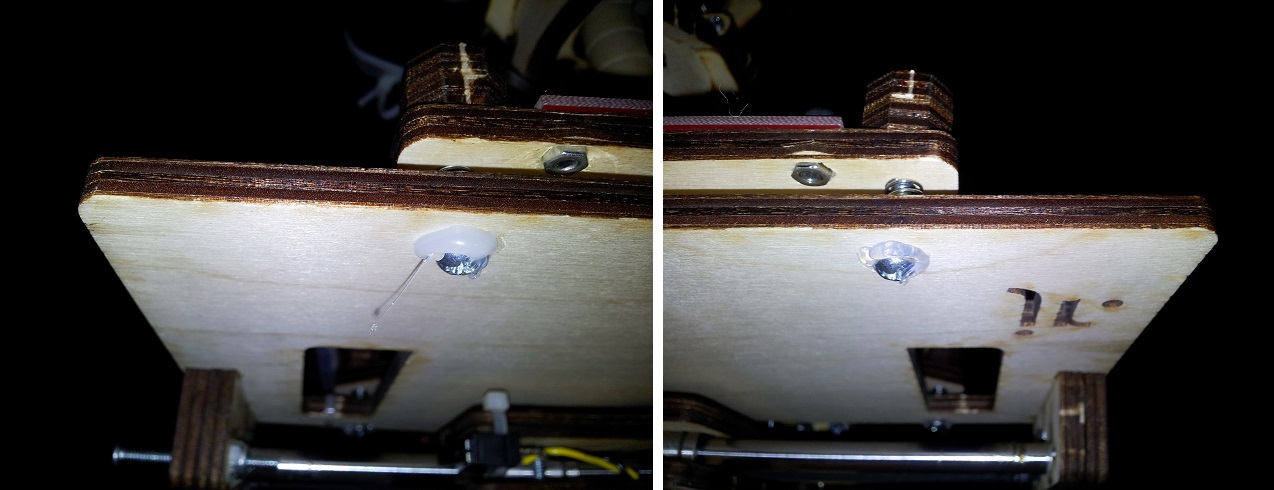
It is better to use a glue gun, having previously pressed on the table, so that the cap with the counter-nut will move away from the Vanera. This will deprive the screws of mobility (they loose enough in the holes in the plywood, above and to which, in fact, they are attached to the heated table itself, which begins to hang out with them) and prevent the screw from turning on the counter washer with a weak tightening (which is literally enrages when you accidentally touch a wooden adjusting nut with your hand, you try to remove the finished part from the table or clean the table, you have to re-calibrate if you have not put the control risks on the nut and on the table and have not noticed, turned whether the nut is more than one turn). But you shouldn't tighten too much, remember, the table should have a stroke along the Z axis, and the springs are only 10 mm long.
Another way to more accurately level the table with wooden nuts manually is to align the contour. Before printing the part itself, the printer usually prints a contour around it, in accordance with the settings of the slicer (if this option is not disabled in the slicer forcibly). As a rule, it is 2 layers in one thread at a distance of 6 mm from the base of the part. So, if you carefully monitor the thickness of the contour right in the process, you can easily determine the thickness of the spread layer, where the table collapses, and right in the process of printing a little bit to tighten or release one or another nut, literally 1/16 of a turn.
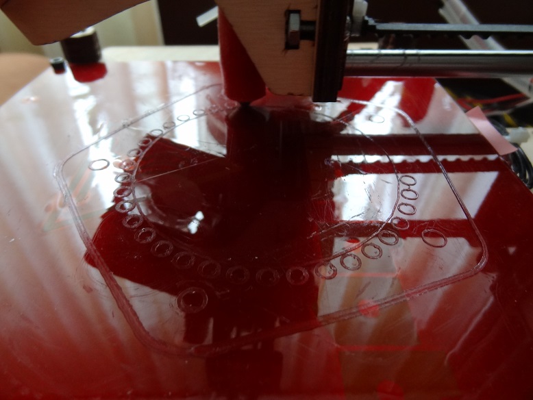
Here, on the little ringlets. it is clearly seen that the left (from the observer on the side) side of the table is slightly higher than the right, and it is necessary to slightly tighten either the two left nuts, or release the right ones.
You can also clearly see a flat table along the contour, or in some places not. And he places yes. Since the base of the table is plywood and in its middle, under the heating element, a sufficiently wide sweep deepening thermo-sensor is cut by the laser, which is also glued to the heater itself with a piece of not thin Kapton ... (this is an engineering pun) then in my particular case the table is stably bent at the corners of their square up. In the middle of the table there is a hole, and taking into account the presence of a piece of Kapton, the effect under it is completely inexplicable, except that during the laser cutting of the notch under the thermal sensor, this part of the plywood has significantly shrunk. In the middle of the sides of the square of the table, too, deflections down. The latter were minimized by placing a piece of paper folded in several layers under the heating element on the sides of the square.
Well, in general, what the rich, bananey dumb.

If suddenly someone offers you to buy a 3D printer with a cold, spring-loaded table (and a nozzle larger than 0.35 mm, but more on that later), loudly fill with satanic laughter and pathetically defile the way to the horizon. And never again visit this unfortunate engineer and do not eat pies with him.
Feels the heart, the fourth part is not to pass ...
This idea somehow did not materialize on paper in the first two parts, but now I will talk about it.
Although this term is now practically and officially not applied, but all our discussions and articles, as well as the message of the RepRap project as a whole, belong to the class of HOUSEHOLD 3D PRINTERS, i.e. Domestic Appliance. And this term will soon be adopted, I am sure.
Printers of this class never, yes, it will never be able to print exactly what was realized in a 3D model, no matter what accuracy the printer manufacturer promises. Here we are talking about accuracy is only in relation to the positioning of the head.
And in practice:
Thus, on a domestic 3D-printer can not print two identical parts. And you can not withstand the exact geometric dimensions without post-printing sandpaper processing.
So do not try, friends!))
You should not treat it as a turning-milling machine. Treat it like an easel. As soon as you accept this state of affairs, Muse Isaakovna immediately presents you with her bust and you will burst out with Christmas toys, hooks in the kitchen and in the bath and endless prototypes that do not require jewelry accuracy.
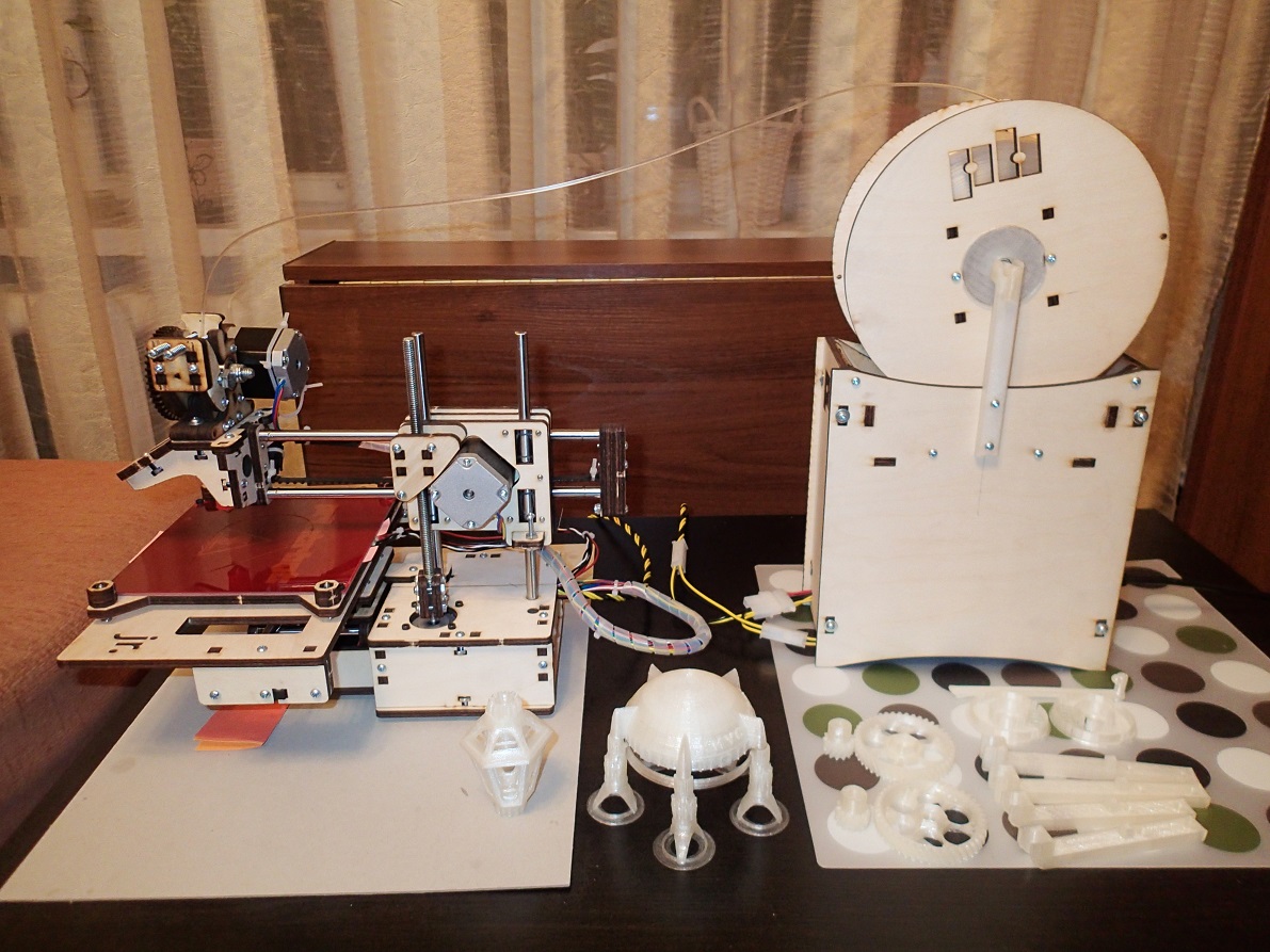
Of course, quite working items are possible without post-printing processing. Those. such products, the required accuracy of execution of which is lower than the actual accuracy of printing. For example, an upgrade for the "power tower" ( Power Tower ) printbot.

The tower is a wooden box for an ATX power supply unit (for feeding a hot table) in the lower part and a specific design with four bearings in the upper part for installing a reel with a rod. Native reel from printbot is also wooden, also cut out on the laser cutter and also completely curve. The four bearings on which it rests do not at all save the situation and under the loud hooting the reel rubs all its bottom against all the inner walls of the box. It is rubbed so much that the printer is unable to wind the bar itself (the bar is stretched so much that the print head rises above the printed layer and the thread goes past, or even the printer simply moves from the spot as the X and Y axes move) that makes you sit next to the printer for several hours, waiting for the end of the process.
Plastic reels did not try, but it is believed that on the side wooden surfaces they will rub the bottom in the same way.
The following elegant solutions raise the reel over the narrow part of the box (there are several wooden inlays, like skids that could be removed, but left so as not to disrupt the integrity of the structure), uses only two of the four bearings and transfers the mounting point of the reel to the axle rotation, minimizing friction and load.
And voila!
Now the printer can work without supervision of a Person or even a computer, the benefit of the built-in SD card allows you to start tasks from it and then turn off the computer.
Or one more example.
As I wrote earlier, after setting up the printer, it is recommended to immediately print a pair of plastic gears of the extruder, instead of wooden ones. This will increase the quality of printing and wear plastic gears, in theory, will be less (with silicone then lubricant). Although, I still don’t see any special wear on my wooden ones, despite the fact that I print four hours every day. But, as you remember, we preliminarily greased the wooden gears with WD-shkoy, and decided to periodically repeat this procedure - this is the result.
Ready 3D models of gears can be found in Tinkercad (in which I work, as a rule) and on Thingiverse , asking in the search for "Helical Gear", which means "helical gear", or "Printrbot gear".
Gears are needed precisely for helical gears and precisely with the right tooth, not triangular! And that is, such craftsmen .
The helical gear will provide a very smooth bar stroke, which will significantly affect the print quality and product surface, and the gear teeth will wear much less than the spur gears.
I strongly recommend not to put Chevron wheels . Their installation requires either loosening and retracting to the side of the extruder motor, or removing and taking notes of both gears simultaneously.
The helical gears can be changed individually and the motor should not be touched.
Themselves helical gears to draw from scratch, the case, I tell you, ungrateful, and SolidWorks to help you. Therefore, as a finished product, I took just such a model with Thingiverse. Gears are made very high quality and with very original "knitting" on the big gear. However, as they say, it is not a sin to process after assembly and file, namely, add chamfers, remove unnecessary in some places and most importantly, add a groove from the back side under the bearing, on a large gear.
You can, of course, put an extra washer of small diameter (as on the bearings of the belt pulling mechanism of the X and Y axes) so that the gear does not touch the outer fixed face of the bearing. But, firstly, an extra washer of the required diameter may not be available (which happened to the Author), so the groove was added by default, and secondly, there was no washer on the blast-diagram ...

Additionally, a seal was added in the bore of the small gear under the output on the motor shaft.
Corrected gear models will soon be posted on Tinkercad. I will update the link in fact.
But in this photo you can clearly see the different quality in different print modes.

Model on the right: 0.22mm layer thickness, the limiter on the maximum frequency of vibration of the printer is 50Hz.
Model on the left: 0.2mm layer thickness, printer vibration limit off.
Print speed is the same, 30mm / s.
The conclusion can be made very interesting.
Firstly, the difference in the thickness of a layer of 0.2 and 0.22mm is palpable both visually and tactilely (which, in principle, should not be, in theory), but true.
Secondly, an interesting option to limit the vibration of the printer (so that the heavy print head does not gouge into the part with frequent and fast changes of direction) works, but not quite correctly. On filling, the effect is visible, the speed is gained gradually. On the perimeter works strange. Then it works on the first figure, but does not work on the next one , it stops right in the middle of a straight line and starts to move again (hence the burrs on the right model).
In the slicer, there are still separate options for accelerating the printhead during various operations, but I have not yet tested it. I can only say that the recommended value of 9000m / s / s is similar to the truth, the vibrations are getting smaller, but the edges of the model are again becoming ragged. I will finish testing - I will write it off in more detail.
Note: this is RepetierHost v0.90 software and the latest version of the slicer Slic3r embedded in it.
In order not to reassure the reader of the vain expectations of the immortal elixir, I can confidently say that there are no ideal parameters for printing. For each detail - the speed and thickness of the layer and the percentage of filling will be their own. And if we consider that different operations must be performed at different speeds, then it is possible to estimate the non-plowed field for experiments.
Since we can, as a result, hypothetically obtain an ideal detail, we can also try to evaluate the family of functions that precedes it, too.
That is, in my humble opinion, since household 3D printers can already be considered entered into narrow masses of interest, it is time to come to light a system of equations describing the dependence of some printing parameters on others.
At the moment, there is no such system (for household printers!). There are only a variety of slicers that allow you to manually change dozens and dozens of different numbers and sliders. The final quality, in this case, can be assessed only upon completion of the work, which is not good or convenient.
Any Jedi who is engaged in 3D printing of household appliances, one way or another tries to find the dependence of the parameters on strength, at least the main ones (layer thickness, speed, percentage of filling), so that manna time and time again not to spend on the selection of parameters for each new truss. Did not pass the C thought and me ...
But alas, so far nothing to boast. I will share only the only proven dependency.
The effective layer thickness is h = d / 1.75 (where d is the diameter of the nozzle, and 1.75 is not the thickness of the rod, but “Author's constant”). Increasing h will reduce print quality, but will increase the speed. A decrease in h in some cases will improve the quality, but will create additional problems with the cooling of the workpiece during the printing process, which ultimately will also kill the workpiece long before the end of printing.
Now, if you look at the previous photo of the two gears again, you will understand why the 0.4mm nozzle, which all manufacturers put as standard in the basic package, should be immediately replaced with a thinner one.
For zatravochka two examples. Thickness of a layer 0.18mm.

Frogs with insufficient cooling, in the style of tear Alohmyachka

Reference frogs
, , … .
"… ".
« . . .» () .
. .
« » (Hot End), , . , , . Ubis Hot End , RepRap, .
, , . , , , .
- :

:
, , , , ( ), -. , 80 100%, .. ( ) .
( ) 100 , . 5.5. . , , 10/. . , .
10 .
Printrbot Jr 100 . .
, . , 80-90% 3-4 ( 80% 193).
, , .
, .))
… , , … , .))
During this arbitrary printing failure was mercilessly defeated, the reel rod upgrade was made and several items for the soul.
And with a new power for the pen ...
In the previous parts, we practically collected our 3D printer ( Part 1 ) and came close to calibrating it ( Part 2 ).
Here I’ll start right now with her. And there, God willing, we will have time to test, but Bolivar will not endure the quadruple part ...
Although, it would be possible to talk a little more about the nuances of the assembly, but looking at the previous material with a critical eye, I can say with confidence that most of the really important points have already been covered. All the rest is quite fit into the model: “Do not feel sorry for glue!” Perhaps, in the process of the third part, something else will emerge, let's see ...
And so, for calibration, please.
My dear!))
')
Desktop
That's right, and let's start with the desktop.
The desktop at Printer bot is correct!
In general, the desktop at the household 3D-printer should be spring-loaded. Those. must have some move down the z axis.
What for? And just so that the calibration process along the Z axis does not turn into a periodic migraine for you. The fact is that no matter what materials a household 3D printer is created from - the table will “float”, warp and shift in different ways relative to the position. We are talking about tenths of a millimeter, but these are exactly the shares that are responsible for the quality of the model's sticking to the table and the quality of the bottom surface, especially its faces and the faces of the holes in it, if any.
Those. already for two main parameters!
- If the part sticks badly to the table, then at some point it will come off and it will not be glued back. We'll have to start the printing process again.
- With the bottom and edges, the situation is as follows. As you know, printing with ABS plastic requires heating the table, otherwise nothing will stick at all. Moreover, as practice shows, printing thin-walled, “openwork” or miniature designs with PLA plastic without heating the table is also impossible — it will stick out at the most erotic moment.
For example, to print a similar rocket with a three-toed base without a hot table is unlikely to succeed, even with heating I had to add stiffeners and a half-millimeter ring at the base to increase the contact area.
Khius. The first Soviet photonic airplane, which was commanded by Anatoly Borisovich Yermakov in September 1991. for the first time he made a successful landing on the planet Venus and delivered a Soviet scientific expedition to the area of Uranova Golkonda. It was the first space flight of Alexei Bykov, a “desert specialist”. The expedition also included geologist Grigori Dauge, pilot Bogdan Spitsyn, navigator Mikhail Krutikov and geologist Vladimir Yurkovsky. Spitsyn and Ermakov died.
In memory of the dead, fifty kilometers to the south of Golkonda, at the spurs of the ridge, in the center, now a city, a monument was erected - the “Boy” tank transporter. They found him, cut him out of the soil and so, together with the melted stone, put him on a plastic base. A short inscription was carved on the armor: “First”. This is a monument to Anatoly Yermakov, Bogdan Spitsyn, Tahmasib Mehdi, his comrades. (WITH)
It is also impossible to print on a cold table a shaft or an axis of small diameter in the lying position, i.e. when the surface of the table touches only one thread of the first layer.
By the way
For the same reason, those who have already ordered the Printrbot Simple, I recommend trying to cancel the order and take on the newly-available Printrbot Jr V2 (available both as an assembly and as Kit). He already has a hot table in the set, Simple does not have it, and there is no way to upgrade.
But the hot table has its own nuance.
Nuance
On a hot table, the first bottom layer in the printing process is melted and spreads a little. You can certainly minimize this effect by reducing the heating temperature of the table, but then the quality of adhesion decreases. Need to choose a compromise. Much depends on the composition and quality of the bar and on the calibration of the temperature sensor). For my bar PLA (bought in a printer with a printer) the compromise is 60C. If more - then the bottom melts and spreads too much, if less - it can peel off on complex structures and with the base of a small area. But in any case, the melting will be, and the first layer (or the first few layers - depending on their thickness) will slightly creep out of the model by the end of the print. In this case, the edge of this layer is similar to a razor - very sharp, and if you print a part, which then needs to be twisted somewhere, a cork, for example, then the probability of cutting yourself is extremely high.
Useful
To minimize this effect, it is necessary to add a chamfer, at least half a millimeter, to the bottom of the 3D model. And it is better to follow the rule in general, when designing 3D models, add chamfers wherever the surfaces intersect at right or sharp angles and have contact with the body. This is a good tone rule, it goes back to safety and GOSTs, just follow it.
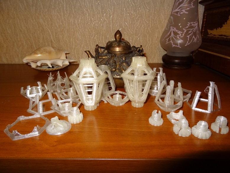
Christmas lantern. The front part shows that even on a hot table the base in the corners begins to flake off. On the plywood table Simpl'a such a candelabrum, most likely, will not succeed. Note the pair of small screw plugs on the right. Hats, made without chamfers at first, painfully and deeply cut the hand when screwing. Survived, packaged.
But then we started with the springs!
So, the spring-loaded table allows you to avoid three fouls at once:
- First foul If for some reason you incorrectly set the minimum height of the nozzle above the surface of the table,
- and it should be 0.1 mm and set as follows: a sheet of plain paper is taken, its thickness is just around 0.1 mm. Next, with four wooden nuts at the corners of the table, adjust the height of the nozzle above the table at nine points - at the four corners of the table, in the middle of four sides and in the middle of the table itself, so that the sheet fits tightly and out into the gap between the nozzle and the table surface. And this is done only after you have preliminarily tightened the wooden nuts for a couple of turns (by eye) approximately set the limit switch of the Z axis so that the nozzle is about a millimeter from the surface of the table (through the light).
or skewed the table, and one part of it rose, or knocked the setting of the adjusting finger for the limit switch of the Z axis ... In short, did some nonsense, as a result of which the table, or part of it, rose more than you need on your passport, then when parking the print head it rests against the surface of the table, and the printer will courageously try to “punch” the table or tear itself onto the British flag, at least bend the axes (and the new Chinese stepper motors, I can tell you, are very much delivered). So, the spring-loaded table will gently take on this unpleasant moment and will not allow the terrible to happen. - Second foul If for some reason the table and the printer withstood each other’s pressure and decided that the situation was parking, then at the next moment the printer starts printing and the head starts to scratch the first layer of your most outstanding piece uncompromisingly. A plywood table will not forgive such a debut for you, and the system as a whole will go into the category of engravers.
On the heated table you will most likely have a Kapton on which the brass nozzle slides quite comfortably. If your table is spring loaded, then there will not even be scratches on the kapton. - The third foul arising from the second. If the movement still began, then after a moment the printer will start feeding the bar into the extruder. And if the nozzle was pressed to the table strongly enough, then the molten plastic will go not through a closed hole 0.4 mm down, but between the bar and the walls of the extruder upwards. And in this case, the spring-loaded table guarantees that the plastic will pass through the nozzle orifice downwards, since the pressure in the nozzle will be much greater than the pressure of the spring-loaded table on the nozzle. And this in turn guarantees you the very beginning of the printing process.
Later on, on the second and third layers, the thickness of the layers is equalized and the printing will proceed with the established thickness of the layer.
In general, during operation, you will most likely first set up the limit switch of the Z axis (which is inconvenient to set up, since one or the other lock nut on the finger is unscrewed during the calibration process), and then you align the table (which is very conveniently adjusted manually with four screws ). Further, for periodic fine tuning, you will use the Z-offset slicer parameter, which allows you to take into account when generating the G-code positive or negative correction values along the Z axis.
For good, the surface of the table, like any other surface, should be leveled at three points, but in practice, the quad nut does not interfere as much as in theory, especially since the plywood-based table “plays” a little and tension is on all four nuts almost always.
But one thing that must be done is to put the table's guide screws on the glue from the counter-washer.
It is better to use a glue gun, having previously pressed on the table, so that the cap with the counter-nut will move away from the Vanera. This will deprive the screws of mobility (they loose enough in the holes in the plywood, above and to which, in fact, they are attached to the heated table itself, which begins to hang out with them) and prevent the screw from turning on the counter washer with a weak tightening (which is literally enrages when you accidentally touch a wooden adjusting nut with your hand, you try to remove the finished part from the table or clean the table, you have to re-calibrate if you have not put the control risks on the nut and on the table and have not noticed, turned whether the nut is more than one turn). But you shouldn't tighten too much, remember, the table should have a stroke along the Z axis, and the springs are only 10 mm long.
Life hacking
Another way to more accurately level the table with wooden nuts manually is to align the contour. Before printing the part itself, the printer usually prints a contour around it, in accordance with the settings of the slicer (if this option is not disabled in the slicer forcibly). As a rule, it is 2 layers in one thread at a distance of 6 mm from the base of the part. So, if you carefully monitor the thickness of the contour right in the process, you can easily determine the thickness of the spread layer, where the table collapses, and right in the process of printing a little bit to tighten or release one or another nut, literally 1/16 of a turn.
Here, on the little ringlets. it is clearly seen that the left (from the observer on the side) side of the table is slightly higher than the right, and it is necessary to slightly tighten either the two left nuts, or release the right ones.
You can also clearly see a flat table along the contour, or in some places not. And he places yes. Since the base of the table is plywood and in its middle, under the heating element, a sufficiently wide sweep deepening thermo-sensor is cut by the laser, which is also glued to the heater itself with a piece of not thin Kapton ... (this is an engineering pun) then in my particular case the table is stably bent at the corners of their square up. In the middle of the table there is a hole, and taking into account the presence of a piece of Kapton, the effect under it is completely inexplicable, except that during the laser cutting of the notch under the thermal sensor, this part of the plywood has significantly shrunk. In the middle of the sides of the square of the table, too, deflections down. The latter were minimized by placing a piece of paper folded in several layers under the heating element on the sides of the square.
Well, in general, what the rich, bananey dumb.
Conclusion
If suddenly someone offers you to buy a 3D printer with a cold, spring-loaded table (and a nozzle larger than 0.35 mm, but more on that later), loudly fill with satanic laughter and pathetically defile the way to the horizon. And never again visit this unfortunate engineer and do not eat pies with him.
Feels the heart, the fourth part is not to pass ...
About dividing crystal dreams, levitating and walking through it all with roses. (WITH)
This idea somehow did not materialize on paper in the first two parts, but now I will talk about it.
Although this term is now practically and officially not applied, but all our discussions and articles, as well as the message of the RepRap project as a whole, belong to the class of HOUSEHOLD 3D PRINTERS, i.e. Domestic Appliance. And this term will soon be adopted, I am sure.
Printers of this class never, yes, it will never be able to print exactly what was realized in a 3D model, no matter what accuracy the printer manufacturer promises. Here we are talking about accuracy is only in relation to the positioning of the head.
And in practice:
- a really flat surface will be only the bottom one, only that one that sticks to the Kapton;
the top surface will be rough no matter how many times you have smoothed it (set in the slicer by the parameter solid top layer); - side surfaces are always, yes, it is always! this roughness will depend on the layer thickness, print temperature (i.e. plasticity), bar uniformity and print speed;
- parallel surfaces, edges or edges cannot be made. Just by virtue of the method of printing, namely the smearing of layers of viscous, flowing and sticky material on each other. No, under no circumstances with this method of printing you will not be able to touch the neighboring threads with a nozzle, not to push a little more plastic than you need and not to hook and pull along just the outermost thread of the contour. And yes, we will not even remember the bridges. Bridges sag.
Thus, on a domestic 3D-printer can not print two identical parts. And you can not withstand the exact geometric dimensions without post-printing sandpaper processing.
So do not try, friends!))
You should not treat it as a turning-milling machine. Treat it like an easel. As soon as you accept this state of affairs, Muse Isaakovna immediately presents you with her bust and you will burst out with Christmas toys, hooks in the kitchen and in the bath and endless prototypes that do not require jewelry accuracy.
Of course, quite working items are possible without post-printing processing. Those. such products, the required accuracy of execution of which is lower than the actual accuracy of printing. For example, an upgrade for the "power tower" ( Power Tower ) printbot.
The tower is a wooden box for an ATX power supply unit (for feeding a hot table) in the lower part and a specific design with four bearings in the upper part for installing a reel with a rod. Native reel from printbot is also wooden, also cut out on the laser cutter and also completely curve. The four bearings on which it rests do not at all save the situation and under the loud hooting the reel rubs all its bottom against all the inner walls of the box. It is rubbed so much that the printer is unable to wind the bar itself (the bar is stretched so much that the print head rises above the printed layer and the thread goes past, or even the printer simply moves from the spot as the X and Y axes move) that makes you sit next to the printer for several hours, waiting for the end of the process.
Plastic reels did not try, but it is believed that on the side wooden surfaces they will rub the bottom in the same way.
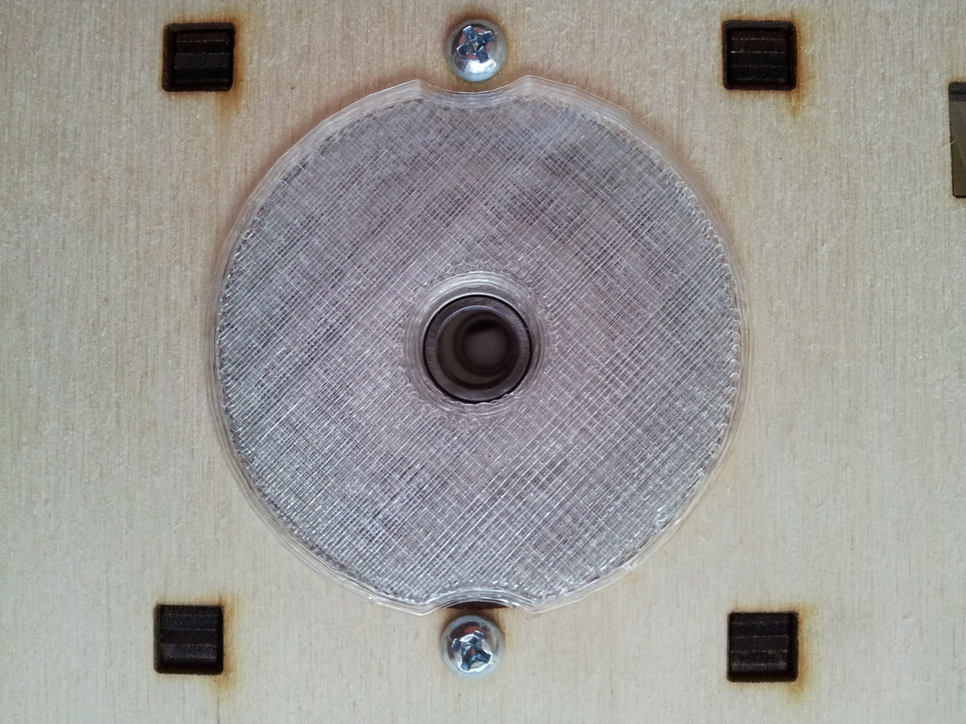
The following elegant solutions raise the reel over the narrow part of the box (there are several wooden inlays, like skids that could be removed, but left so as not to disrupt the integrity of the structure), uses only two of the four bearings and transfers the mounting point of the reel to the axle rotation, minimizing friction and load.
Four large photos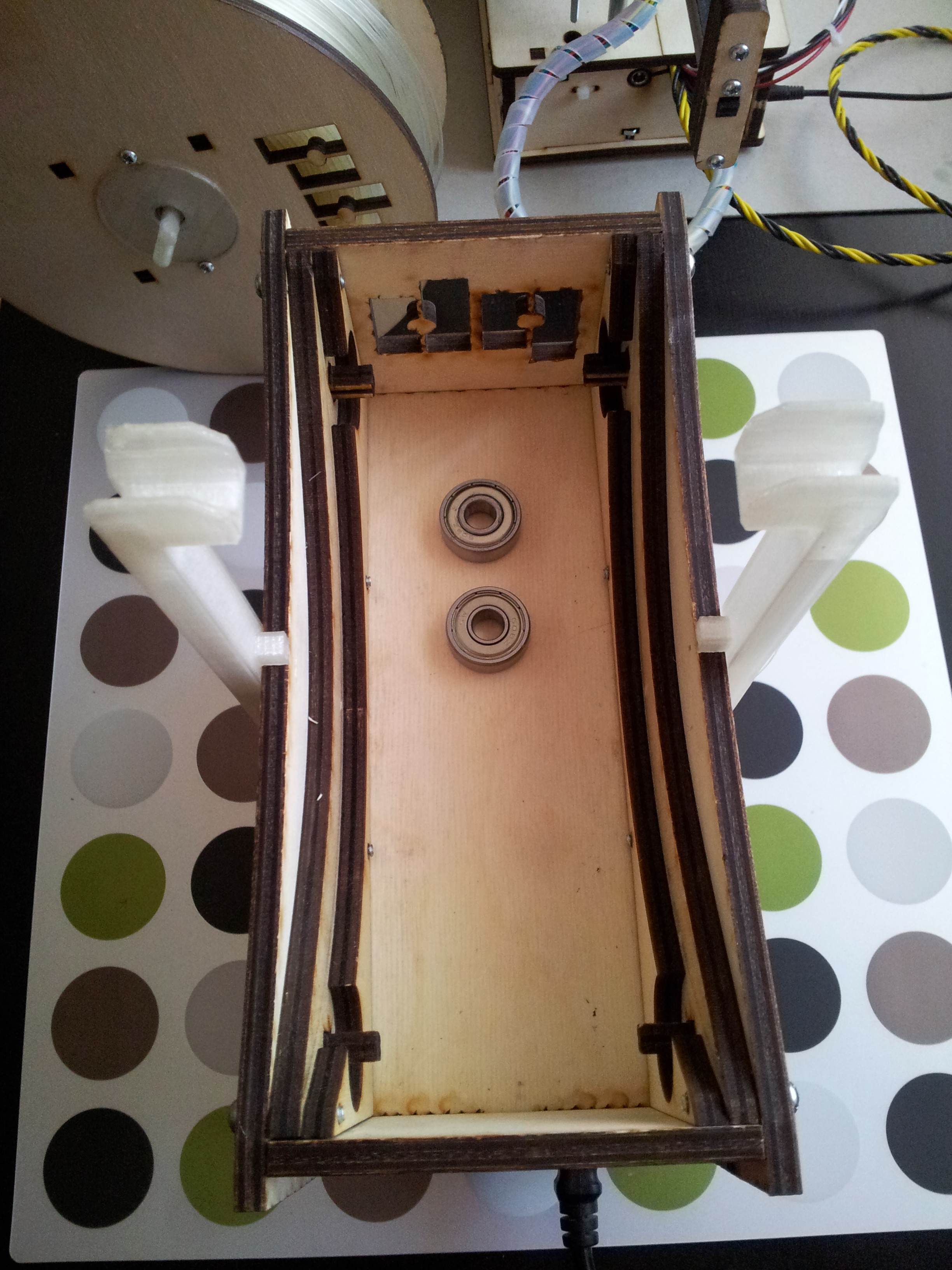

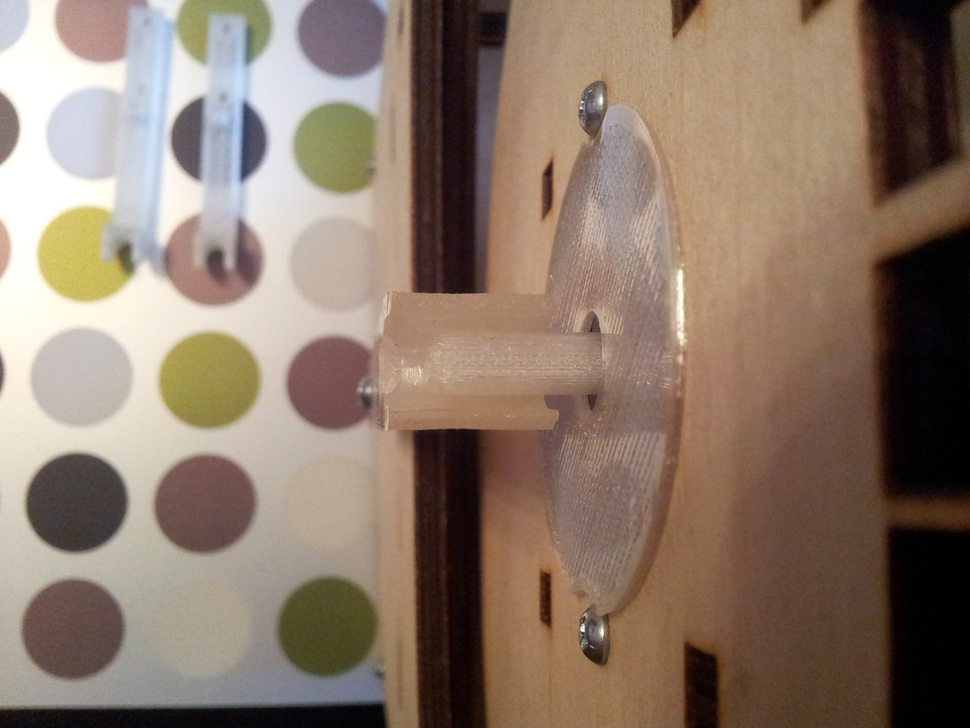
And voila!
Now the printer can work without supervision of a Person or even a computer, the benefit of the built-in SD card allows you to start tasks from it and then turn off the computer.
Or one more example.
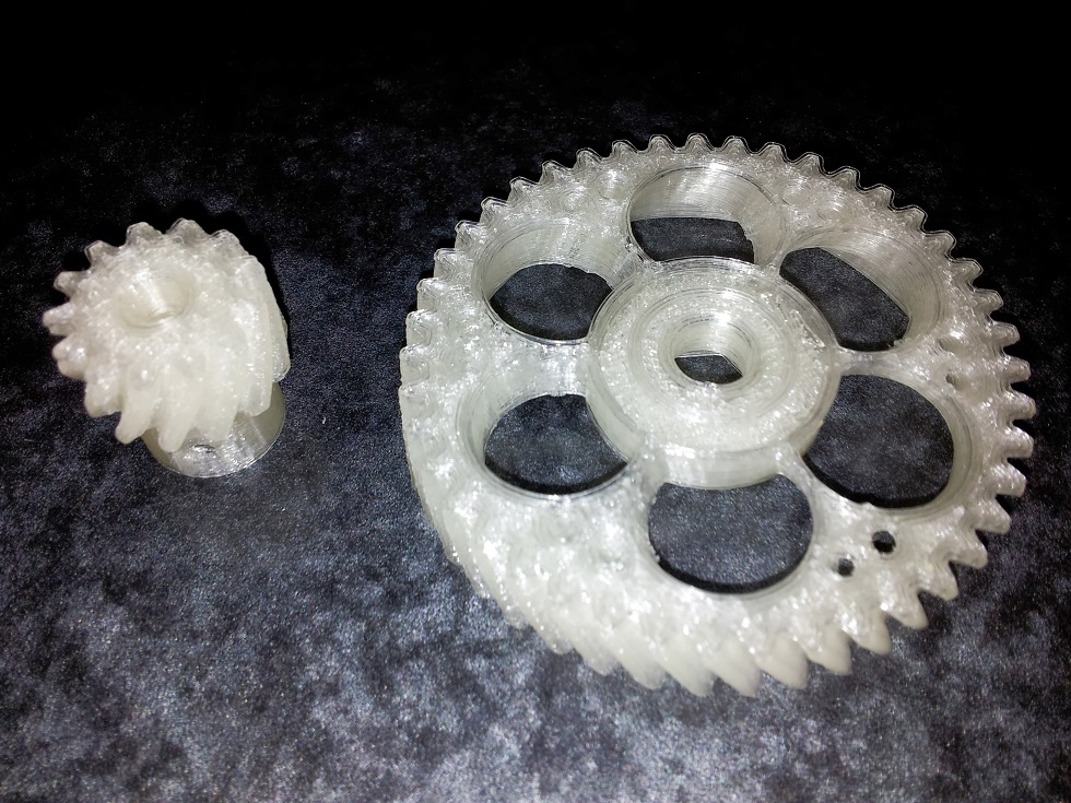
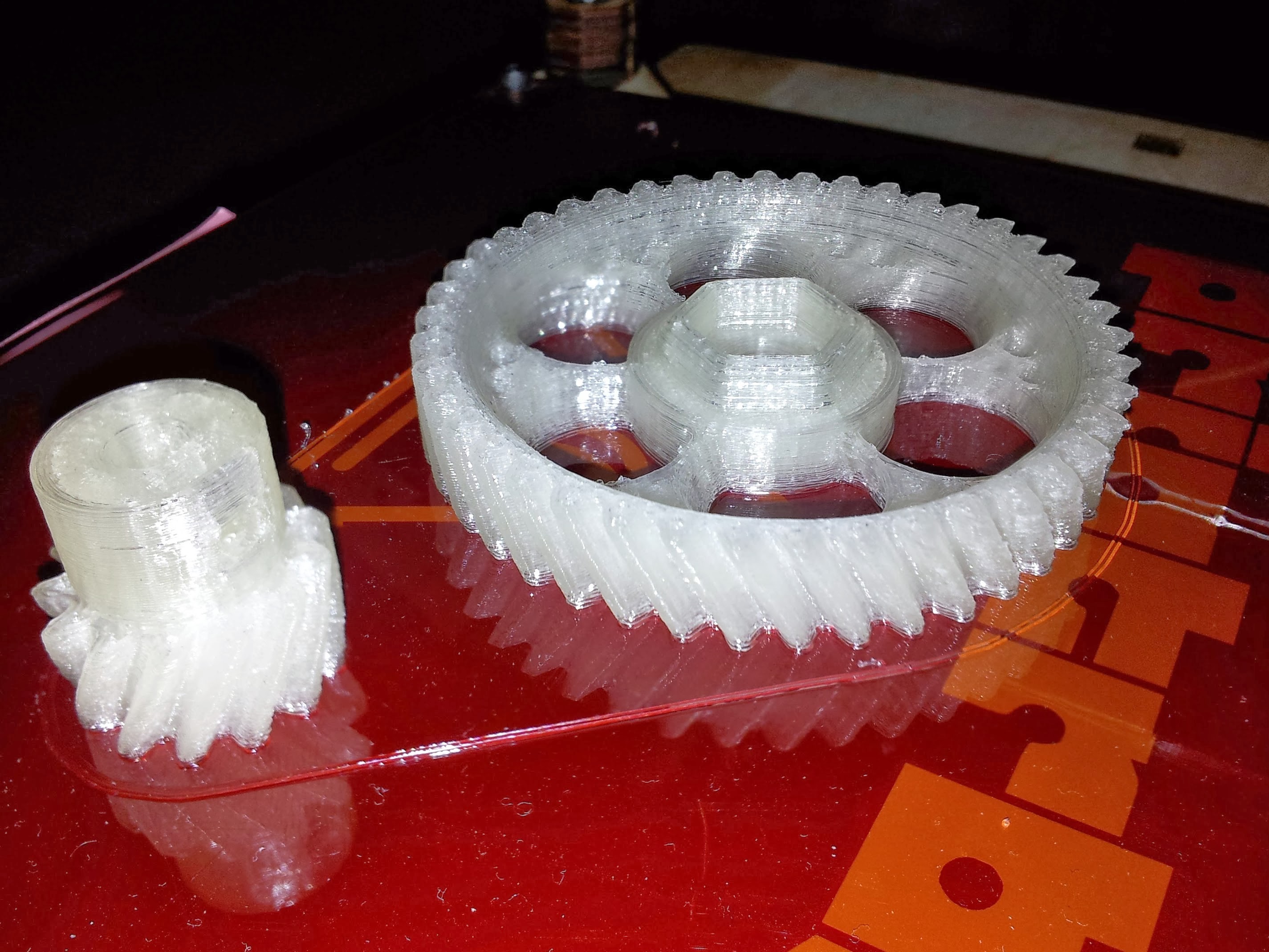
As I wrote earlier, after setting up the printer, it is recommended to immediately print a pair of plastic gears of the extruder, instead of wooden ones. This will increase the quality of printing and wear plastic gears, in theory, will be less (with silicone then lubricant). Although, I still don’t see any special wear on my wooden ones, despite the fact that I print four hours every day. But, as you remember, we preliminarily greased the wooden gears with WD-shkoy, and decided to periodically repeat this procedure - this is the result.
Ready 3D models of gears can be found in Tinkercad (in which I work, as a rule) and on Thingiverse , asking in the search for "Helical Gear", which means "helical gear", or "Printrbot gear".
Gears are needed precisely for helical gears and precisely with the right tooth, not triangular! And that is, such craftsmen .
The helical gear will provide a very smooth bar stroke, which will significantly affect the print quality and product surface, and the gear teeth will wear much less than the spur gears.
I strongly recommend not to put Chevron wheels . Their installation requires either loosening and retracting to the side of the extruder motor, or removing and taking notes of both gears simultaneously.
The helical gears can be changed individually and the motor should not be touched.
Themselves helical gears to draw from scratch, the case, I tell you, ungrateful, and SolidWorks to help you. Therefore, as a finished product, I took just such a model with Thingiverse. Gears are made very high quality and with very original "knitting" on the big gear. However, as they say, it is not a sin to process after assembly and file, namely, add chamfers, remove unnecessary in some places and most importantly, add a groove from the back side under the bearing, on a large gear.
You can, of course, put an extra washer of small diameter (as on the bearings of the belt pulling mechanism of the X and Y axes) so that the gear does not touch the outer fixed face of the bearing. But, firstly, an extra washer of the required diameter may not be available (which happened to the Author), so the groove was added by default, and secondly, there was no washer on the blast-diagram ...
Additionally, a seal was added in the bore of the small gear under the output on the motor shaft.
Corrected gear models will soon be posted on Tinkercad. I will update the link in fact.
But in this photo you can clearly see the different quality in different print modes.
Model on the right: 0.22mm layer thickness, the limiter on the maximum frequency of vibration of the printer is 50Hz.
Model on the left: 0.2mm layer thickness, printer vibration limit off.
Print speed is the same, 30mm / s.
The conclusion can be made very interesting.
Firstly, the difference in the thickness of a layer of 0.2 and 0.22mm is palpable both visually and tactilely (which, in principle, should not be, in theory), but true.
Secondly, an interesting option to limit the vibration of the printer (so that the heavy print head does not gouge into the part with frequent and fast changes of direction) works, but not quite correctly. On filling, the effect is visible, the speed is gained gradually. On the perimeter works strange. Then it works on the first figure, but does not work on the next one , it stops right in the middle of a straight line and starts to move again (hence the burrs on the right model).
In the slicer, there are still separate options for accelerating the printhead during various operations, but I have not yet tested it. I can only say that the recommended value of 9000m / s / s is similar to the truth, the vibrations are getting smaller, but the edges of the model are again becoming ragged. I will finish testing - I will write it off in more detail.
Note: this is RepetierHost v0.90 software and the latest version of the slicer Slic3r embedded in it.
About the eternal
In order not to reassure the reader of the vain expectations of the immortal elixir, I can confidently say that there are no ideal parameters for printing. For each detail - the speed and thickness of the layer and the percentage of filling will be their own. And if we consider that different operations must be performed at different speeds, then it is possible to estimate the non-plowed field for experiments.
But
Since we can, as a result, hypothetically obtain an ideal detail, we can also try to evaluate the family of functions that precedes it, too.
That is, in my humble opinion, since household 3D printers can already be considered entered into narrow masses of interest, it is time to come to light a system of equations describing the dependence of some printing parameters on others.
At the moment, there is no such system (for household printers!). There are only a variety of slicers that allow you to manually change dozens and dozens of different numbers and sliders. The final quality, in this case, can be assessed only upon completion of the work, which is not good or convenient.
Any Jedi who is engaged in 3D printing of household appliances, one way or another tries to find the dependence of the parameters on strength, at least the main ones (layer thickness, speed, percentage of filling), so that manna time and time again not to spend on the selection of parameters for each new truss. Did not pass the C thought and me ...
But alas, so far nothing to boast. I will share only the only proven dependency.
The effective layer thickness is h = d / 1.75 (where d is the diameter of the nozzle, and 1.75 is not the thickness of the rod, but “Author's constant”). Increasing h will reduce print quality, but will increase the speed. A decrease in h in some cases will improve the quality, but will create additional problems with the cooling of the workpiece during the printing process, which ultimately will also kill the workpiece long before the end of printing.
Now, if you look at the previous photo of the two gears again, you will understand why the 0.4mm nozzle, which all manufacturers put as standard in the basic package, should be immediately replaced with a thinner one.
About cooling
For zatravochka two examples. Thickness of a layer 0.18mm.
Frogs with insufficient cooling, in the style of tear Alohmyachka
Reference frogs
And a couple of amphibians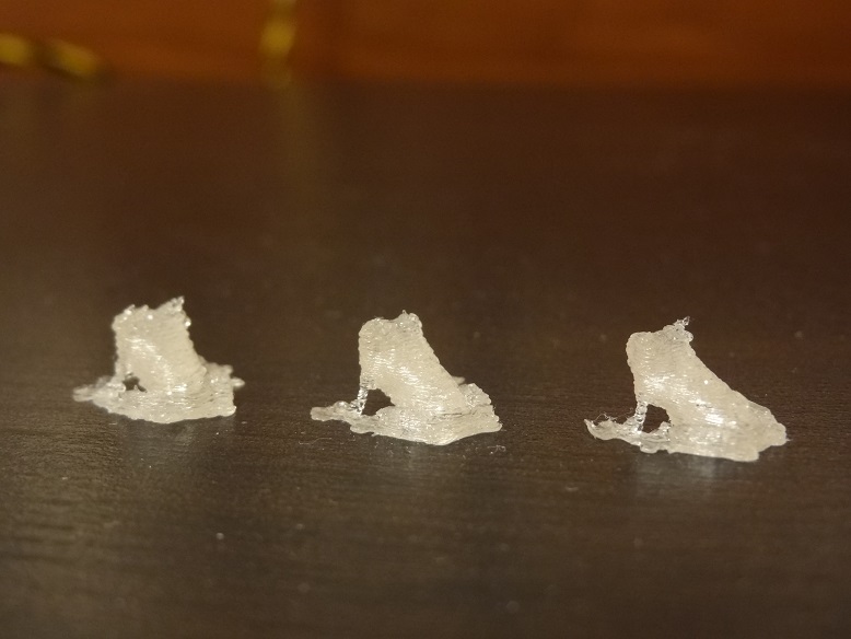
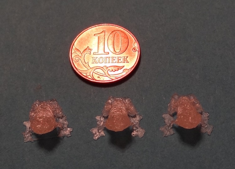
Left to right, layer thickness: 0.22mm, 0.20mm, 0.18mm
, 0.20 .
Left to right, layer thickness: 0.22mm, 0.20mm, 0.18mm
, 0.20 .
, , … .
"… ".
So here
« . . .» () .
. .
« » (Hot End), , . , , . Ubis Hot End , RepRap, .
, , . , , , .
- :
:
, , , , ( ), -. , 80 100%, .. ( ) .
( ) 100 , . 5.5. . , , 10/. . , .
10 .
Printrbot Jr 100 . .
, . , 80-90% 3-4 ( 80% 193).
, , .
, .))
P.S
- , ( , , ) , , . PLA, ( , , , 100% «» ) , . , . .
- , ! , . . , .
… , , … , .))
Source: https://habr.com/ru/post/201834/
All Articles