Radio modem for $ 7
Good time of day!
I will tell you how you can assemble a 100mW radio modem at 433 MHz for yourself, at a cost of about 6-7 dollars. Powerful radio modem for 200 rubles - is it tempting? Then let's get started.
Wanted soldering skills a little above average and ordering experience in online stores.
The modem consists of a Si4432 radio module and an ATMega8 / 168/328 based controller that controls it. Any suitable. If you use older versions (168 and 328), the modem parameter configurator will be a bit prettier. The radio module is powered by 3.3 volts through the AMS1117-3.3 stabilizer. The processor is powered by 5 volts, and operates at 16 MHz, the frequency is stabilized by quartz. The communication lines with the radio module are matched by the voltage level with the help of zener diodes.
Also, apart from the actual components of the modem, for its repetition you will need: ISP programmer and FTDI adapter (I did not buy the device by reference, but it looks interesting - supposedly it has an ISP). You can do only ISP programmer.
The attentive reader will immediately notice, saying, “What modem for 7 bucks, if only the 328th mega is 200 rubles?” And also notice that all references in the specification lead to online stores. Unfortunately, if you buy components in Russia, the modem will come out gold (as, by the way, everything that is produced in Russia). Therefore, in order to achieve the minimum cost - it is necessary to order radio components in China. The negative point - will have to wait for the arrival of the parcels. However, Si4432 and so ordered in Asia, so it will still have to wait. Often, a batch of 10 pieces, the same ATMega328, is obtained at a price the same as a batch of 5 pieces. It is necessary to monitor prices and look for a suitable option.
So after all, from where 7 dollars? We consider:
Si4432 - $ 4
ATMega8 - $ 0.8 (only a batch of 10 pcs.)
AMS1117 - $ 1 (in fact, these are 10 stabilizers ($ 0.1) in a batch of 20)
Tumbler - LEDs 2x5 rubles, resistors-capacitors - 10x0.3 + 4x4 rubles (of course, if you are not buying in chipidip)
If we categorically do not want to buy radio parts in lots - well, then the modem will rise in price for a dollar due to the price of mega.
The fee is free or 10 rubles, etching solution, soldering iron, solder, etc. - I do not take into account, because these are not disposable things, and someone probably already has them.
The schematic diagram of the device is shown in the figure below:
The printed circuit board was divorced in Sprint Layout in 2 versions: for the antenna-coil, and for the installation of the RF connector type SMA. Both options are optimized for LUT. If you do not like the mesh fill (better for LUT) - you can turn on the solid in the editor.

')
The assembly takes place in 2 stages:
On the first - small parts are installed, stabilizer, processor.
After that, you need to flash the processor using the ISP programmer with Arduino bootloader. This is done to simplify your life - after uploading the bootloader, there is no need to poke the ISP into the board to fill in the new firmware. Test firmware is being poured in order not to burn the radio module.
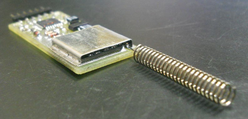
At the second stage, the radio module is installed on the board, after which the “combat” firmware is poured.

Actually, in the image 1 - the etched board, 2 - small things are installed, 3 - the test firmware is flooded, 4 - the radio module is installed, the board is varnished, 5 - the screen is installed from interference, from tin.
The modem firmware is written in Arduino. No programmer from me (I am an engineer) - therefore the quality of the code is very so-so. You can tell where to improve something - I will be glad.
The program is based on the OpenBee project . Actually, my changes are a setup mode that was not made in the original firmware, and a fix for the jamb with clearing the transmission buffer. Also in the original firmware was a cant - the frequency was not tuned (it was define, but then the data was erased with data from the EEPROM, which was never recorded) and the device’s RFID tag. Now everything is set up.
The firmware process is as follows:
A bootloader is recorded using an ISP. For the board on mega8 - bootloader for the board “Arduino NG or older w / ATMega8”. For the board on mega 168 and 328 - “Arduino Pro or Pro mini (5V, 16MHz) w / ATMega 168” and “Arduino Pro or Pro mini (5V, 16MHz) w / ATMega 328”, respectively.
Test firmware is recorded. Already directly from Arduino. It initializes the EEPROM, blinks the LEDs, and sets all the legs of the processor to High-Z mode.
Well, and lastly, the working firmware is recorded. Also from Arduino.
The modem is configured when the modem is turned on with the “SET” pin closed at + 5V.
At the same time, a port menu is issued to the port at a speed of 9600 baud, in which you can change the working frequency, the speed of the serial port and the radio module, and so on. RFID tag (RF Header), in which the modems "interlock" with each other.
Be sure to configure the radio tag to separate your modems from other devices. The OLRS label is highly discouraged (this is the default label for all Open LRS devices to which the modem belongs).
The test and “combat” firmware from Arduino is recorded using a standard USB-UART converter on FTDI. The connector on the modem is not compatible with the standard "Arduinovsky", connect the RX-TX, TX-RX, DTR-Reset, +5, GND. If there is no FTDI in the farm (as it is ???) - the firmware can be poured using ISP.
There is an unresolved flaw in the firmware. In theory, the speed of the serial port is limited to 115K. However, due to the recording in EEPROM uint - in fact, the speed can be no more than 65535 baud. In this connection, the plug is set up - when 65534 is exceeded - 57600 is recorded. If there is a desire, you can disable the configuration from the computer and set the speed in the firmware. However, it makes little sense to do this - no, because the maximum speed in the aero channel is 57600.
There is also a limit on the length of the packet received on the serial port. This is 37 bytes. This restriction was introduced by the authors of the original project, and, apparently, due to the buffer depth of the radio module (64 bytes). Here I did not change anything.
Sources, drawings of the printed circuit board, scheme - are in the catalog by reference .
If 100 mW is not enough for you - there is an option to remake this modem into the RFM23BP module. Its output power is 1 watt.
It should be understood that the use of such a thing is illegal in this country.
UPD.
Based on a comment. I checked the wave resistance of the track to the SMA connector. In principle, everything was not bad (60 ohms), however, to heighten the agreement, I slightly changed the width of the track. Replaced the board file.
I will tell you how you can assemble a 100mW radio modem at 433 MHz for yourself, at a cost of about 6-7 dollars. Powerful radio modem for 200 rubles - is it tempting? Then let's get started.
Wanted soldering skills a little above average and ordering experience in online stores.
How it all began
I wanted to telemetry on the copter. But buying a ready-made 3DRadio radio modem - the toad strangled, for a pair costs $ 39. It was decided to make a functional counterpart, but not so expensive. On the occasion, I bought the RFM22B radio modules, and tested them on the open-source OpenBee project. It turned out around $ 22 a pair (google on request "openbee 433 MHz"). Having obtained a satisfactory result, it was decided to make the construction even cheaper, using their cheap Si4432 counterparts instead of expensive RFM22.
Design
The modem consists of a Si4432 radio module and an ATMega8 / 168/328 based controller that controls it. Any suitable. If you use older versions (168 and 328), the modem parameter configurator will be a bit prettier. The radio module is powered by 3.3 volts through the AMS1117-3.3 stabilizer. The processor is powered by 5 volts, and operates at 16 MHz, the frequency is stabilized by quartz. The communication lines with the radio module are matched by the voltage level with the help of zener diodes.
Component Specification
Si4432 - 100mW 433MHz radio module manufactured by Silabs.
ATMega8 or ATMega168 or ATMega328
Quartz Murata CSTCE16M0V53-R0 16MHz. In principle, output quartz will do, but you will have to install it on the back of the board, and you will need capacitors on the ground.
AMS1117-3.3 (LM1117)
VD1-VD3 - BZV55C3V3 - 3,3V zener diode, without conclusions
VD4 - LL4148 (DL4148) - rectifying diode, also without pins
C1 - 1000pF (size 0805). You can not set.
C2, C3 - 4.7 ... 25 uF tantalum (size 1210)
C4 - 0.1uF (0.01 ... 0.2uF)
R1-R3 - 470 Ohms (470 ... 510)
R4, R5 - 4.7 K (4.7 ... 10K)
R6, R7 - 1K (0 ... 2K)
R8, R9 - 330 ohms (220 ... 680)
R0 - 0 Ohm - jumper
All resistors size 0805, in parentheses indicate the possible range of values, however, it is better to adhere to these.
LED1, LED2 - SMD LEDs, size 0805, different colors.
Also, apart from the actual components of the modem, for its repetition you will need: ISP programmer and FTDI adapter (I did not buy the device by reference, but it looks interesting - supposedly it has an ISP). You can do only ISP programmer.
The attentive reader will immediately notice, saying, “What modem for 7 bucks, if only the 328th mega is 200 rubles?” And also notice that all references in the specification lead to online stores. Unfortunately, if you buy components in Russia, the modem will come out gold (as, by the way, everything that is produced in Russia). Therefore, in order to achieve the minimum cost - it is necessary to order radio components in China. The negative point - will have to wait for the arrival of the parcels. However, Si4432 and so ordered in Asia, so it will still have to wait. Often, a batch of 10 pieces, the same ATMega328, is obtained at a price the same as a batch of 5 pieces. It is necessary to monitor prices and look for a suitable option.
So after all, from where 7 dollars? We consider:
Si4432 - $ 4
ATMega8 - $ 0.8 (only a batch of 10 pcs.)
AMS1117 - $ 1 (in fact, these are 10 stabilizers ($ 0.1) in a batch of 20)
Tumbler - LEDs 2x5 rubles, resistors-capacitors - 10x0.3 + 4x4 rubles (of course, if you are not buying in chipidip)
If we categorically do not want to buy radio parts in lots - well, then the modem will rise in price for a dollar due to the price of mega.
The fee is free or 10 rubles, etching solution, soldering iron, solder, etc. - I do not take into account, because these are not disposable things, and someone probably already has them.
Scheme and fee
The schematic diagram of the device is shown in the figure below:
The printed circuit board was divorced in Sprint Layout in 2 versions: for the antenna-coil, and for the installation of the RF connector type SMA. Both options are optimized for LUT. If you do not like the mesh fill (better for LUT) - you can turn on the solid in the editor.
')
Board assembly
The assembly takes place in 2 stages:
On the first - small parts are installed, stabilizer, processor.
After that, you need to flash the processor using the ISP programmer with Arduino bootloader. This is done to simplify your life - after uploading the bootloader, there is no need to poke the ISP into the board to fill in the new firmware. Test firmware is being poured in order not to burn the radio module.
At the second stage, the radio module is installed on the board, after which the “combat” firmware is poured.
Actually, in the image 1 - the etched board, 2 - small things are installed, 3 - the test firmware is flooded, 4 - the radio module is installed, the board is varnished, 5 - the screen is installed from interference, from tin.
Firmware
The modem firmware is written in Arduino. No programmer from me (I am an engineer) - therefore the quality of the code is very so-so. You can tell where to improve something - I will be glad.
The program is based on the OpenBee project . Actually, my changes are a setup mode that was not made in the original firmware, and a fix for the jamb with clearing the transmission buffer. Also in the original firmware was a cant - the frequency was not tuned (it was define, but then the data was erased with data from the EEPROM, which was never recorded) and the device’s RFID tag. Now everything is set up.
The firmware process is as follows:
A bootloader is recorded using an ISP. For the board on mega8 - bootloader for the board “Arduino NG or older w / ATMega8”. For the board on mega 168 and 328 - “Arduino Pro or Pro mini (5V, 16MHz) w / ATMega 168” and “Arduino Pro or Pro mini (5V, 16MHz) w / ATMega 328”, respectively.
My ISP way
The method is called "Voodoo", it's easy to guess why =)
The method is called "Voodoo", it's easy to guess why =)
Test firmware is recorded. Already directly from Arduino. It initializes the EEPROM, blinks the LEDs, and sets all the legs of the processor to High-Z mode.
About pouring in mega 8
When uploading to megu8 there is an unpleasant moment - the bootloader starts for a very long time (about 6 seconds). It may be necessary to force a reset by closing the reset foot to the ground. This should be done at the moment when the inscription “Uploading ...” appears in the arduino (to close and immediately release the reset - I did this with tweezers so that the legs are near)
Well, and lastly, the working firmware is recorded. Also from Arduino.
Customization
The modem is configured when the modem is turned on with the “SET” pin closed at + 5V.
At the same time, a port menu is issued to the port at a speed of 9600 baud, in which you can change the working frequency, the speed of the serial port and the radio module, and so on. RFID tag (RF Header), in which the modems "interlock" with each other.
Be sure to configure the radio tag to separate your modems from other devices. The OLRS label is highly discouraged (this is the default label for all Open LRS devices to which the modem belongs).
Running a rake
For those interested
Naturally, it was not without jambs. Carefully looking at the picture of the printed circuit board and the assembled device - it is clear that they are different. The jamb showed up suddenly - the modem sent the data, but did not receive anything. It turned out that the foot of the nIRQ radio module is wound up on the D2 mega for a reason. It causes an interrupt (which I initially overlooked in the code). Moreover, the interruption is generated only from the feet D2 or D3. I, for convenience of distributing, got nIRQ on D5. I had to re-breed. As a result, nIRQ is running on D3. It was also a mistake to start the output of the radio module on MISO atmega initially. When programming mega with a soldered module - there is a real chance to burn the radio module. Overdone
The test and “combat” firmware from Arduino is recorded using a standard USB-UART converter on FTDI. The connector on the modem is not compatible with the standard "Arduinovsky", connect the RX-TX, TX-RX, DTR-Reset, +5, GND. If there is no FTDI in the farm (as it is ???) - the firmware can be poured using ISP.
There is an unresolved flaw in the firmware. In theory, the speed of the serial port is limited to 115K. However, due to the recording in EEPROM uint - in fact, the speed can be no more than 65535 baud. In this connection, the plug is set up - when 65534 is exceeded - 57600 is recorded. If there is a desire, you can disable the configuration from the computer and set the speed in the firmware. However, it makes little sense to do this - no, because the maximum speed in the aero channel is 57600.
There is also a limit on the length of the packet received on the serial port. This is 37 bytes. This restriction was introduced by the authors of the original project, and, apparently, due to the buffer depth of the radio module (64 bytes). Here I did not change anything.
I want to repeat!
Sources, drawings of the printed circuit board, scheme - are in the catalog by reference .
Option for bad guys (s)
If 100 mW is not enough for you - there is an option to remake this modem into the RFM23BP module. Its output power is 1 watt.
It should be understood that the use of such a thing is illegal in this country.
UPD.
Based on a comment. I checked the wave resistance of the track to the SMA connector. In principle, everything was not bad (60 ohms), however, to heighten the agreement, I slightly changed the width of the track. Replaced the board file.
Source: https://habr.com/ru/post/201366/
All Articles