USB support in KolibriOS: what's inside? Part 5: logic level
 Device connection processing, started at the host controller support level , has stopped, preparing the zero device endpoint for operation. The channel support level has provided methods for working with channels. It’s time to use them to continue the device initialization: the
 usb_new_device function from bus / usb / protocol.inc is usb_new_device .Now the device can do little: it has not yet received an address on the bus, it has not yet been configured, it can use only 100 mA of bus power. In general, all that a device can do is to tell about itself in response to relevant questions. The story about the device itself is organized in the form of descriptors . A
GET_DESCRIPTOR issue is the GET_DESCRIPTOR command sent to the null endpoint; the command must specify the type of descriptor , the sequence number of the descriptor among all with this type, the length of the data to be transmitted. Each command to the control endpoint takes 8 bytes and may or may not have additional data; in some commands some fields are not used. The command structure by byte and the fields used are described in Chapter 9 of the USB specification, here I will only describe the input and output data for the commands.The logic device level has two tasks: first, configure the device; secondly, ask him, download the appropriate driver — or even drivers — and inform the driver about the new device.
')
The first steps
usb_new_device starts by creating a channel to the zero end point of the device. The host controllers support code before calling usb_new_device filled in the structure describing the device, all that remains is to specify the endpoint parameters: the number — zero — and the maximum packet size. The maximum packet size for a control endpoint can vary from 8 to 64 bytes and is recorded among the first 8 bytes of the device descriptor. However, to read the descriptor, you need an already open channel. Fortunately, you can get out of the dependency cycle: the maximum packet size is needed only to break one transfer into transactions; it is guaranteed that the maximum packet size for the control endpoint is at least 8 bytes; if during the initial stages of the configuration only data of length 8 bytes or less is transmitted, then the exact value of the maximum packet size is unimportant. Therefore, as the maximum value of the packet, you can set any number, not less than 8 bytes.However, there is one problem: the EHCI emulation in VirtualBox is not entirely correct and requires 64 bytes to work with HighSpeed devices. Since there are no other requirements, the channel to the zero endpoint begins to exist with a maximum packet size of 64 bytes.
Until the device receives an address on the bus, it responds to the zero address and prevents the reset of subsequent devices — if another device is reset, both devices will respond to packets with a zero address, which will lead to confusion on the bus. Therefore, the first thing that
usb_new_device does after opening a channel is to select the first unallocated address and send the SET_ADDRESS command. At the entrance of the command SET_ADDRESS - address, there is no output.After completing the
SET_ADDRESS command, the usb_set_address_callback procedure receives usb_set_address_callback . If the device did not respond to the command or responded with an error, then the only option is to disconnect the device from the bus at the hub level. If the command is successful, usb_set_address_callback informs the support level of the host controllers that the address has changed; for the reasons I mentioned in one of the previous articles in the series , the change may take some time. In both cases, the zero address on the bus ceases to be occupied, so you can begin to reset subsequent devices, if any; the call to usb_test_pending_port is responsible for this.When the host controller confirms the address change in the structure describing the device, the support code calls
usb_after_set_address . Now the representations of the host controller and the device about the address on the bus are reconfigured, you can continue the configuration. The next command usb_after_set_address sends the question GET_DESCRIPTOR , requesting the first 8 bytes of the device descriptor — descriptor type 1, descriptor number 0. The last of these 8 bytes sets the maximum packet size for the zero end point — the last thing that was missing for full communication. The usb_get_descr8_callback response usb_get_descr8_callback pulls out the maximum packet size, reports it to the host controller, and waits for confirmation. After confirmation, call usb_after_set_endpoint_size , where the GET_DESCRIPTOR question for the device descriptor is repeated, now requesting data completely.Device handle
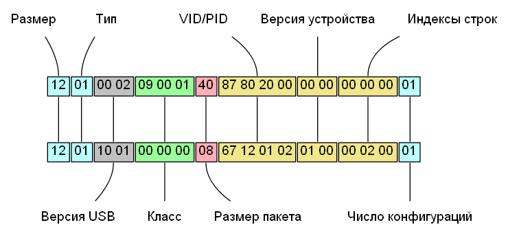
The figure shows the hexadecimal dumps of the descriptors of two different devices: on the top — the virtual hub of RMH, on the bottom — of a mouse. The device handle consists of the following data in little-endian :
- the first byte of any descriptor is its size, the second is its type, the device descriptor is of type 1;
- USB specification version, with which the device is compatible, in BCD ,
110h- version 1.1,200h- version 2.0; - class, subclass and protocol of the device as a whole; often there are zeros, then the data is set at the level of individual interfaces - it will be further about them;
- maximum packet size for the zero end point;
- Vendor ID and Product ID of the device - the USB Implementers Forum association allocates to each USB device manufacturer a double-byte Vendor ID, sometimes even not one, the manufacturer assigns each product a separate double-byte Product ID; for example, Vendor ID
8087hassigned to Intel; - the device version is an arbitrary number that the manufacturer recorded here:
- three pointers to lines, each of which may be missing. The first two are the texts for the user, the manufacturer and product description lines respectively, the last is the serial number. The lines themselves are stored in separate type 3 descriptors;
- number of configurations.
KolibriOS always selects the first device configuration. The
usb_get_descr_callback function, called after reading the device descriptor, sends the GET_DESCRIPTOR command for the first configuration descriptor — type 2, number 0.Together with the configuration descriptor, the device returns many other descriptors that specify the configuration details. The total amount of data associated with the configuration descriptor is not known in advance, but is contained in the configuration descriptor itself. Therefore, the request proceeds in two stages - at the first stage, the
usb_get_descr_callback function requests 8 bytes, at the second stage, the usb_know_length_callback function pulls the total size from the read bytes and requests it already.Configuration descriptor
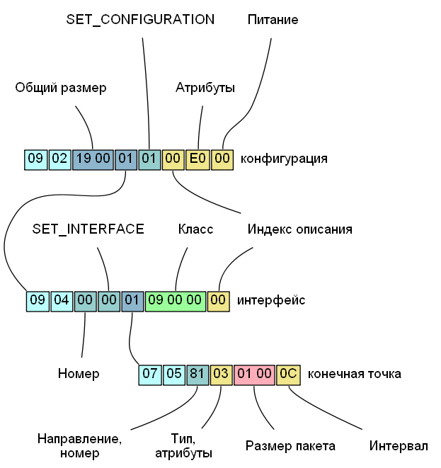
One of the simplest configurations is the virtual hub of RMH, it is shown in the figure. Together with the configuration descriptor, the device returns descriptors of all interfaces of this configuration, for each interface descriptors of all its endpoints. Associated data includes other types of descriptors — for example, HID devices like mice and keyboards return a HID descriptor between an interface descriptor and an endpoint descriptor; parsing them is a matter of driver.
The configuration descriptor consists of the following data:
- size and type, like all descriptors; configuration descriptor is type 2;
- the total size of all associated data, in the example with RMH it is 9 + 9 + 7 = 19h;
- number of interfaces;
- the byte parameter of the
SET_CONFIGURATIONcommand corresponding to the described configuration; - the index of the configuration description string for the user, usually absent - set as 0;
- the attribute byte is the high bit and the low 5 bits are reserved, the 5th bit means wake-up support from the sleepy state in response to some external action, the 6th bit means that the device has its own USB-powered power source;
- The maximum bus power used in this configuration, 1 unit = 2 mA, a value of 50 corresponds to 100 mA.
Interface Descriptor:
- size and type, like all descriptors; configuration descriptor is type 4;
- interface number and interface mode identifier. For some devices, one interface can operate in several modes. Example - webcams: depending on the resolution of the image and the codec, the speed of data flow can vary significantly, different modes reserve different bandwidths of the end point transmitting data. In such cases, there are several descriptors for the same interface, in which the number field is the same, but mode identifiers differ. By default, after selecting the configuration, the interfaces operate in zero mode, the driver can send the
SET_INTERFACEcommand to switch the mode of one interface; - the number of end points;
- class, subclass, and interface protocol. Classes, except
0FFh, are defined by the USB Implementers Forum association, their descriptions are collected on this page . For example, hubs are class 9. Class0FFhused for devices not falling into any other class; - The interface description string for the user, usually absent - specified as 0.
The endpoint descriptor specifies the parameters needed to open the channel:
- size and type, like all descriptors; the endpoint descriptor is type 5;
- direction - high bit - and number - 4 low bits - end point; for example,
81hmeans point number 1, transmitting data from the device to the host; - Endpoint type: 0 = control, 1 = isochronous, 2 = data sets, 3 = interrupts; for isochronous points, specifying parameters are packed in the same byte;
- 11 bits of the maximum packet size for this end point plus 2 more bits for HighSpeed points, specifying the maximum number of transactions per microframe;
- Desired polling interval for isochronous and interrupt type points. For LowSpeed / FullSpeed-type interruption points, the interval is specified in milliseconds, for HighSpeed-type interruption points, the interval is 2 value-1 microframes. In the RMH example, 2 11/8 milliseconds = 0.256 seconds is obtained. For isochronous points, the interval is 2 value-1 in units of measurement that correspond to speed: milliseconds for FullSpeed, microframes for HighSpeed.
The
usb_set_config_callback function, after receiving the complete data associated with the configuration descriptor, SET_CONFIGURATION command with a parameter taken from the descriptor; no output from this command. After successful completion of the command, the device becomes fully functional. The last function of the logic unit level, usb_got_config_callback , parses the resulting configuration data: makes sure that the device does not try to cheat by replacing the total data size between the GET_DESCRIPTOR commands; passes through the list of descriptors, ignoring everything except interface descriptors; for zero-mode descriptors, determines the driver by device class, loads the driver and calls its AddDevice function, passing a pointer to the configuration data and a pointer to the desired interface descriptor inside them. For further work with the device meets the loaded driver. I will talk about existing KolibriOS drivers in subsequent articles.All articles of the series
Part 1: general scheme
Part 2: Basics of working with host controllers
Part 3: Host Controller Support Code
Part 4: Channel Support Level
Part 5: logic level
Part 6: hub driver
Source: https://habr.com/ru/post/200172/
All Articles