Testing terminals VCS Huawei TE30
Testing of the new Huawei TE30 video conferencing terminals, conducted using the ANUE emulator of the ANUE cloud and Metrotek hardware probes, showed that with packet losses of up to 0.8 - 1%, the quality of video communication remains within the normal range. With the inclusion of loss compensation algorithms, the system copes well with packet losses of up to 10%.
The IP cloud emulator used during testing allows normalized delays and distortions to be introduced into packet traffic, simulating the operation of a real network. By varying the distortion combinations, one can estimate the quality of the video conferencing system, as well as obtain a set of parameters for the maximum permissible packet losses, delays, packet jitter and minimum channel capacity, at which the quality of the video conferencing system is still satisfactory.
')
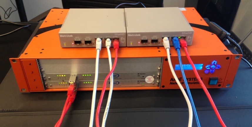
In addition, Metrotek EtherNID probes were used to monitor the state of the network. These devices allow you to control the quality of Ethernet data transmission channels at speeds of 10, 100 or 1000 Mbps. The probes are included in the gap of the Ethernet data transmission channel, freely pass the payload in the channel and simultaneously generate additional measurement traffic, which is terminated by other probes and is used to analyze the parameters of the quality of the Ethernet channels. The main feature of the probes is the Bypass mode, in which when the probe is disconnected from power, it rigidly closes the copper contacts and becomes a passive network device that completely allows user traffic.
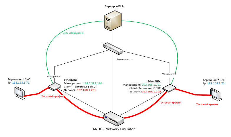
Equipment connection diagram
Description of terminals VKS Huawei TE30
Tests were subjected to the Huawei TE30-720 video conferencing terminal. These devices are built on the principle of "all in one": in one compact product are integrated codec, video camera and audio microphones. For video, you can use not only a standard wired Ethernet connection, but also wireless channels WiFi and 3G / LTE. 3G / LTE support, implemented using a USB modem, is unique to video conferencing devices.
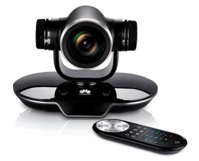
The TE30 video camera provides 1080p resolution and 12x optical zoom. The range of the built-in stereo microphone is up to 6 m. In addition, an external microphone panel can be connected to the system. Echo cancellation technology, automatic gain control and acoustic noise suppression make it possible to achieve a cleaner sound.
The specialized TE30 processor and the H.264 High Profile and Video Motion Enhancement 2.0 algorithms provide high video quality even on low-speed communication channels. The H.264 SVC scalable coding technology, SEC 3.0 loss compensation, and IRC bandwidth adaptation allow maintaining a stable video quality on communication channels with losses of up to 20%. These characteristics of video conferencing systems are especially important for Russia, where the regions still lack high-quality high-speed channels.
Scenario: The equipment is connected according to the scheme above. On the IP cloud emulator, packet losses are set at intervals of 1 out of 100 (1%) in one direction only (loss distribution form: uniform). The number of generated test packets from each measuring probe: 10 packets per second.
Condition: for the purity of experiments in the network, with the exception of the measuring probes and terminals of the VCS, nothing else works.
Total: Over the measurement period (~ 15 minutes), statistics was obtained, according to which the average value of the packet loss coefficient was:
0.976% * (forward)
0.978% * (in reverse)
* This error is related to the uneven distribution pattern of packet loss (profile on emulator uniform), which is interconnected with operational statistics obtained through aggregation of data from the buckets (raw data block) of the probe, from which, in turn, statistics are collected for the portal.
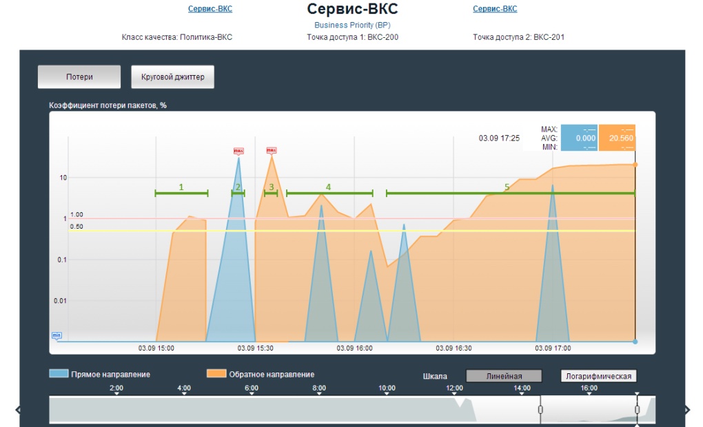
Graph of measurement results from wiSLA portal - “Packet loss coefficient”
Steps 2 and 3: System Bypass Verification
Scenario: On the IP cloud emulator, all changes are disabled. The number of generated test packets from each measuring probe: 10 packets per second.
First, the first probe (stage 2) is turned off by power, and after a short period of time (~ 20 seconds), we turn on the power again. When the power is turned off, the picture does not deteriorate, the video conferencing session is not interrupted. But after turning on the power and full loading of the probe, the picture hangs for 2-3 seconds, but the session itself does not break. This is due to the auto-negotiation of the interfaces between the probe and the IP cloud emulator.
Then, turn off the power of the second probe (step 3), and after a short period of time (~ 20 seconds), turn on the power again. The results are the same.
Bottom line: the video conferencing system works even with a short channel disconnection.
The average value of the packet loss rate was:
~ 30% (in the forward direction)
~ 31% (on the contrary)
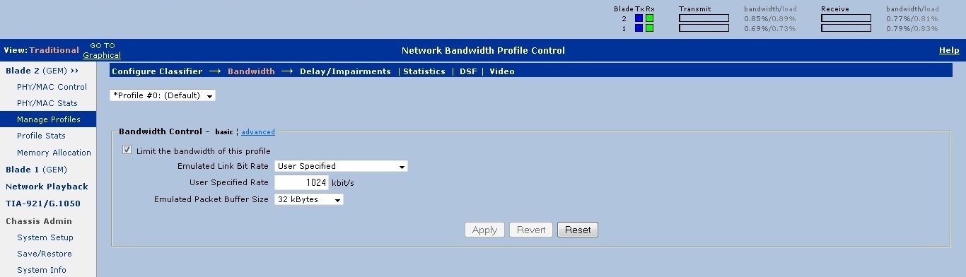
Scenario: According to the wiring diagram of the equipment, we start testing on probes. We start VKS on terminals. On the IP cloud emulator, the maximum bandwidth of the channel is set, above which traffic will be cut off. The number of generated test packets from each measuring probe: 10 packets per second. At the same time, the automatic image adjustment system is disabled.
Result: We observe periodic artifacts on the screens, a scattering of the picture, while the graph of the frame loss ratio “walks”. The minimum bandwidth was determined: 1024 kbps. At the same time, the call quality was set to 768K (720p). There was no point in reducing the image quality.

Scenario: According to the wiring diagram of the equipment, we start testing on probes. We start VKS on terminals. On the IP cloud emulator, packet losses are set at intervals of 1 in 1000 (0.1%) to 20 out of 100 (20%) in one direction (loss distribution form: uniform). The number of generated test packets from each measuring probe: 10 packets per second.
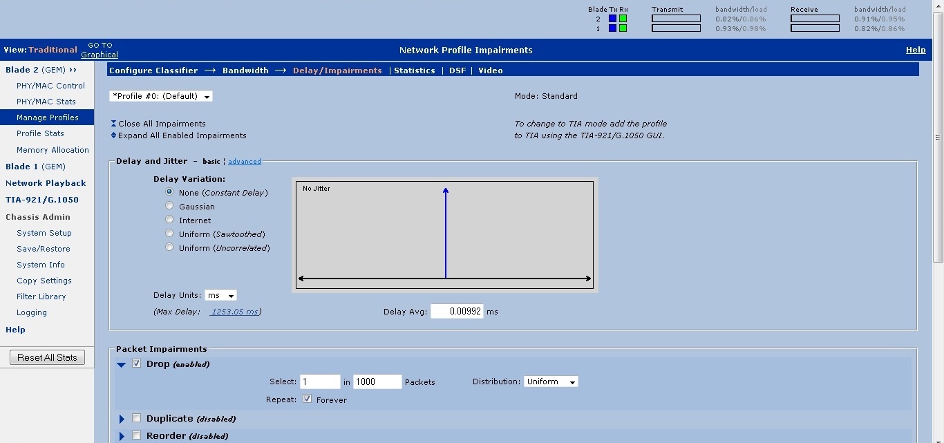

When testing video conferencing systems with the parameters specified above, the communication quality was within the normal range with packet losses of up to 0.8 - 1%; if this threshold was exceeded, artifacts began to appear. It is worth noting that in the terminals there are loss compensation algorithms that allow for increasing the packet loss rate in the automatic mode to reduce the resolution of the video stream and use FEC (Forward Error Correction), but the channel load increases, and a delay appears. In this case, the system copes fairly well with packet losses of up to 10%. The actual bandwidth used by the terminal during the test did not exceed 0.86 Mbps
Bottom line: The system is very stable. With a static picture, when there is little movement in the frame, 5% packet loss is almost not noticeable. When you turn on the loss compensation algorithm, the system copes well with packet losses of up to 10%. With a static picture and the presence of the specified algorithm, the allowable percentage of losses can be even higher.
Note: The discrepancy between the test results and the manufacturer’s data is due to differences in the method of measuring the level of errors. The test used a statistical accounting model for a period of five minutes or more, while the emulator introduced errors randomly, as can be seen in Fig. The terminal uses a different error accounting model and measures the instantaneous level, showing the number of errors per fixed number of recently received packets. In other words, to estimate the level of errors, the terminal uses a sliding window in several packages. With a random distribution of errors on the window may account for a different number of lost packets. Which is also confirmed by the test results with a statistical error level of 10%, the terminal showed fluctuations in the error level from 1% to 20%
The IP cloud emulator used during testing allows normalized delays and distortions to be introduced into packet traffic, simulating the operation of a real network. By varying the distortion combinations, one can estimate the quality of the video conferencing system, as well as obtain a set of parameters for the maximum permissible packet losses, delays, packet jitter and minimum channel capacity, at which the quality of the video conferencing system is still satisfactory.
')
In addition, Metrotek EtherNID probes were used to monitor the state of the network. These devices allow you to control the quality of Ethernet data transmission channels at speeds of 10, 100 or 1000 Mbps. The probes are included in the gap of the Ethernet data transmission channel, freely pass the payload in the channel and simultaneously generate additional measurement traffic, which is terminated by other probes and is used to analyze the parameters of the quality of the Ethernet channels. The main feature of the probes is the Bypass mode, in which when the probe is disconnected from power, it rigidly closes the copper contacts and becomes a passive network device that completely allows user traffic.
Equipment connection diagram
Description of terminals VKS Huawei TE30
Tests were subjected to the Huawei TE30-720 video conferencing terminal. These devices are built on the principle of "all in one": in one compact product are integrated codec, video camera and audio microphones. For video, you can use not only a standard wired Ethernet connection, but also wireless channels WiFi and 3G / LTE. 3G / LTE support, implemented using a USB modem, is unique to video conferencing devices.
The TE30 video camera provides 1080p resolution and 12x optical zoom. The range of the built-in stereo microphone is up to 6 m. In addition, an external microphone panel can be connected to the system. Echo cancellation technology, automatic gain control and acoustic noise suppression make it possible to achieve a cleaner sound.
The specialized TE30 processor and the H.264 High Profile and Video Motion Enhancement 2.0 algorithms provide high video quality even on low-speed communication channels. The H.264 SVC scalable coding technology, SEC 3.0 loss compensation, and IRC bandwidth adaptation allow maintaining a stable video quality on communication channels with losses of up to 20%. These characteristics of video conferencing systems are especially important for Russia, where the regions still lack high-quality high-speed channels.
Step 1: Calibrate the system and check connections
Scenario: The equipment is connected according to the scheme above. On the IP cloud emulator, packet losses are set at intervals of 1 out of 100 (1%) in one direction only (loss distribution form: uniform). The number of generated test packets from each measuring probe: 10 packets per second.
Condition: for the purity of experiments in the network, with the exception of the measuring probes and terminals of the VCS, nothing else works.
Total: Over the measurement period (~ 15 minutes), statistics was obtained, according to which the average value of the packet loss coefficient was:
0.976% * (forward)
0.978% * (in reverse)
* This error is related to the uneven distribution pattern of packet loss (profile on emulator uniform), which is interconnected with operational statistics obtained through aggregation of data from the buckets (raw data block) of the probe, from which, in turn, statistics are collected for the portal.
Graph of measurement results from wiSLA portal - “Packet loss coefficient”
Steps 2 and 3: System Bypass Verification
Scenario: On the IP cloud emulator, all changes are disabled. The number of generated test packets from each measuring probe: 10 packets per second.
First, the first probe (stage 2) is turned off by power, and after a short period of time (~ 20 seconds), we turn on the power again. When the power is turned off, the picture does not deteriorate, the video conferencing session is not interrupted. But after turning on the power and full loading of the probe, the picture hangs for 2-3 seconds, but the session itself does not break. This is due to the auto-negotiation of the interfaces between the probe and the IP cloud emulator.
Then, turn off the power of the second probe (step 3), and after a short period of time (~ 20 seconds), turn on the power again. The results are the same.
Bottom line: the video conferencing system works even with a short channel disconnection.
The average value of the packet loss rate was:
~ 30% (in the forward direction)
~ 31% (on the contrary)
Stage 4: Selecting the minimum channel bandwidth
Scenario: According to the wiring diagram of the equipment, we start testing on probes. We start VKS on terminals. On the IP cloud emulator, the maximum bandwidth of the channel is set, above which traffic will be cut off. The number of generated test packets from each measuring probe: 10 packets per second. At the same time, the automatic image adjustment system is disabled.
Result: We observe periodic artifacts on the screens, a scattering of the picture, while the graph of the frame loss ratio “walks”. The minimum bandwidth was determined: 1024 kbps. At the same time, the call quality was set to 768K (720p). There was no point in reducing the image quality.
Step 5: Verifying the quality of video conferencing systems with different packet loss rates.
Scenario: According to the wiring diagram of the equipment, we start testing on probes. We start VKS on terminals. On the IP cloud emulator, packet losses are set at intervals of 1 in 1000 (0.1%) to 20 out of 100 (20%) in one direction (loss distribution form: uniform). The number of generated test packets from each measuring probe: 10 packets per second.
When testing video conferencing systems with the parameters specified above, the communication quality was within the normal range with packet losses of up to 0.8 - 1%; if this threshold was exceeded, artifacts began to appear. It is worth noting that in the terminals there are loss compensation algorithms that allow for increasing the packet loss rate in the automatic mode to reduce the resolution of the video stream and use FEC (Forward Error Correction), but the channel load increases, and a delay appears. In this case, the system copes fairly well with packet losses of up to 10%. The actual bandwidth used by the terminal during the test did not exceed 0.86 Mbps
Bottom line: The system is very stable. With a static picture, when there is little movement in the frame, 5% packet loss is almost not noticeable. When you turn on the loss compensation algorithm, the system copes well with packet losses of up to 10%. With a static picture and the presence of the specified algorithm, the allowable percentage of losses can be even higher.
Note: The discrepancy between the test results and the manufacturer’s data is due to differences in the method of measuring the level of errors. The test used a statistical accounting model for a period of five minutes or more, while the emulator introduced errors randomly, as can be seen in Fig. The terminal uses a different error accounting model and measures the instantaneous level, showing the number of errors per fixed number of recently received packets. In other words, to estimate the level of errors, the terminal uses a sliding window in several packages. With a random distribution of errors on the window may account for a different number of lost packets. Which is also confirmed by the test results with a statistical error level of 10%, the terminal showed fluctuations in the error level from 1% to 20%
Source: https://habr.com/ru/post/199484/
All Articles